EP0051287A1 - Klimatisierungsverfahren und -system für ein Kraftfahrzeug - Google Patents
Klimatisierungsverfahren und -system für ein Kraftfahrzeug Download PDFInfo
- Publication number
- EP0051287A1 EP0051287A1 EP81109289A EP81109289A EP0051287A1 EP 0051287 A1 EP0051287 A1 EP 0051287A1 EP 81109289 A EP81109289 A EP 81109289A EP 81109289 A EP81109289 A EP 81109289A EP 0051287 A1 EP0051287 A1 EP 0051287A1
- Authority
- EP
- European Patent Office
- Prior art keywords
- air
- air temperature
- passenger compartment
- temperature
- mix door
- Prior art date
- Legal status (The legal status is an assumption and is not a legal conclusion. Google has not performed a legal analysis and makes no representation as to the accuracy of the status listed.)
- Granted
Links
Images




Classifications
-
- B—PERFORMING OPERATIONS; TRANSPORTING
- B60—VEHICLES IN GENERAL
- B60H—ARRANGEMENTS OF HEATING, COOLING, VENTILATING OR OTHER AIR-TREATING DEVICES SPECIALLY ADAPTED FOR PASSENGER OR GOODS SPACES OF VEHICLES
- B60H1/00—Heating, cooling or ventilating devices
- B60H1/00642—Control systems or circuits; Control members or indication devices for heating, cooling or ventilating devices
- B60H1/00814—Control systems or circuits characterised by their output, for controlling particular components of the heating, cooling or ventilating installation
- B60H1/00821—Control systems or circuits characterised by their output, for controlling particular components of the heating, cooling or ventilating installation the components being ventilating, air admitting or air distributing devices
- B60H1/00835—Damper doors, e.g. position control
Definitions
- the present invention relates to an air-conditioning method and system used for an automotive vehicle, and more specifically to the air-conditioning method and system in which air temperature at which the passenger compartment is maintained is automatically adjusted to match variations in the passengers' perception of comfortable temperature according to the seasons.
- an automotive vehicles have been provided with an air conditioner which can maintain air temperature within the passenger compartment at an appropriate temperature.
- a prior-art air-conditioning system air is drawn in through an air intake duct by a blower fan and is cooled by a cooling unit. After being cooled, one part of the introduced air is heated by a heating unit and is proportioned with the other unheated part of the introduced air by an air mix door in order to maintain the air within the passenger compartment in a desired temperature. Further, in this case, an air intake door is usually provided in order to selectably effect outside-air introduction or inside-air recirculation.
- the outside-air introduction mode is used for refreshing the air within the passenger compartment with fresh air and the inside-air recirculation mode is used for cooling or heating the air within the passenger compartment efficiently.
- the air mix door is opened or closed by an air mix door actuator, which is controlled by two solenoid valves.
- the solenoid valves are energized by using a bridge circuit including various resistors of a passenger compartment air temperature sensor, an outside-air temperature sensor, an air mix door opening percentage sensor, a passenger compartment air temperature presetting variable resistor, fixed resistors, etc.
- the passenger compartment temperature at which a passenger will be comfortable will tend to be a little lower in summer and a little higher in winter.
- the air-conditioning method of controlling the passenger compartment air at a comfortable temperature according to the outside air temperature includes steps by which a comfortable passenger compartment air temperature T O ' is calculated on the basis of the outside-air temperature T A and the desired preset passenger compartment air temperaure TO in accordance with a predetermined relationship defined by three linear functions having two points of intersection, next the basic outlet duct air temperature TACO is calculated on the basis of the calculated comfortable passenger compartment air temperature T O ' and the detected outside-air temperature T A in accordance with a first equation, thirdly an outlet duct air temperature correction AT is calculated on the basis of the calculated comfortable passenger compartment air temperature T O ' and the detected passenger compartment air temperature Tp in accordance with a second equation, fourthly the calculated basic outlet duct air temperature TACO and the calculated outlet duct air temperature correction AT are added to obtain the target outlet duct air temperature T AC , fifthly the added target outlet duct air temperature T AC and the passenger compartment air temperature Tp are compared with the predetermined relationships of outlet duct air temperature T AC
- the air-conditioning system of controlling the passenger compartment air at a comfortable temperature according to the outside air temperature comprises various sensors, such as outside air temperature sensor, a passenger compartment air temperature sensor and an air mix door opening percentage sensor, a passenger compartment air temperature preset device, and an arithmetic control unit including a preset passenger compartment air temperature correction unit, a basic outlet duct air temperature calculating unit, an outlet duct air temperature correction calculating unit, an adder, an air mix door open percentage calculating unit, in addition to a comparator, an actuator, etc.
- Fig. 1 shows a diagrammatical illustration of a sample prior-art air-conditioning system.
- air is drawn in through an air intake duct 3 by a blower fan 2 driven by a motor 1 and is cooled by a cooling unit 4.
- a heating unit 6 After being cooled, one part of the introduced air is heated by a heating unit 6 and is mixed in proportion to the other unheated part of introduced air according to the opening percentage of an air mix door 5, and lastly outputted from a number of air outlet ducts 7, 8, and 9 into the passenger compartment.
- the reference numeral 10 denotes a compressor
- the numeral 11 denotes an actuator for positioning the air mix door 5
- the numeral 12 denotes a sensor for detecting the opening percentage of the air mix door
- the numeral 13 denotes a slide switch linked to the air mix door
- the numerals 14 and 15 denote solenoid valves to activate the actuator 11; that is, the numeral 14 denotes a solenoid valve to introduce a vacuum pressure in the engine intake manifold into the actuator 11 to change the air mix door opening percentage in one direction
- the numeral 15 denotes a solenoid valve to release the pressure of the actuator 11 to atmospheric pressure to change the air mix door opening percentage in the opposite direction.
- the source of air drawn in by the blower fan 2 is determined by an air intake door 16.
- the above-mentioned air conditioning system is conventionally controlled by a bridge circuit as shown in Fig. 2.
- the bridge circuit comprises a passenger compartment air temperature sensor R p , an outside-air temperature sensor R a , a first fixed resistor R 1 , a second fixed resistor R 2 , a passenger compartment air temperature presetting variable resistor VR o , a variable resistor VR used for the air mix door opening percentage sensor, and a fixed resistor R h across which an output voltage is taken.
- connection.points C and E, and D and F are connected to two comparators 20 and 21 respectively.
- the solenoid valve 14 is actuated by a solenoid valve actuation circuit 22, so that vacuum pressure is introduced into the actuator 11 of Fig. 1.
- the solenoid valve 15 is actuated by a solenoid valve actuation circuit 23, so that vacuum pressure is relieved from the actuator 11 of Fig. 1.
- the opening percentage of the air mix door 5 is adjusted.
- the passenger compartment temperature at which passenger will be comfortable will tend to be a little lower in summer and to a little higher in winter.
- the above-mentioned heat quantity Q AC to be supplied to the passenger compartment is determined by the difference in temperature between air outputted from an air conditioning system T AC and air within a passenger compartment Tp.
- the thermal loads Q T and Q v are determined by the difference in temperature between outside air T A and inside, that is passenger compartment air Tp.
- the solar heat temperature T S is determined by incident solar energy. Accordingly, since Q M and Q I are roughly constant, it is also possible to express the above equation (1) as another temperature equilibrium equation as follows: where T AC is the target temperature of air outputted from an air conditioning system, Tp is the passenger compartment air temperature, T A is the outside-air temperature, T S is the expectable increase of passenger compartment temperature due to solar heat, and a, b, c and d are constants.
- the above-mentioned basic outlet duct air temperature TACO is calculated in accordance with the above equation (3).
- a comfortable passenger compartment air temperature T O ' calculated by a preset temperature correction unit is substituted into the . preset passenger compartment air temperature T O .
- the comfortable passenger compartment air temperature T O ' is the value of the preset air temperature TO adjusted in inverse proportion to outs.ide air temperature T A , so that changes in passenger perception of comfort are taken into account automatically.
- the outside air temperature T A and the passenger compartment air temperature Tp are actually detected by respective temperature sensors.
- the passenger compartment air temperature increase T S due to solar heat and constants a, b, c and d are all fixed and previously stored in an appropriate memory unit.
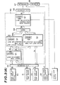
- Fig. 3(A) shows a schematic block diagram of a first embodiment of an air conditioning system according to the present invention.
- the numeral 30 denotes a passenger compartment air temperature presetting device outputting a signal T O
- the reference numeral 31 denotes an outside-air temperature sensor outputting a signal T A
- the numeral 32 denotes a passenger compartment air temperature sensor outputting a signal Tp.
- the reference numeral 33 denotes an air mix door opening percentage sensor for detecting the opening percentage of the air mix door of Fig. 1 and outputting a signal X' indicative thereof.
- the numeral 34 denotes an analog- degital converter to convert the outside-air temperature signal T A , the passenger compartment air preset temperature signal T O , and the passenger compartment air temperature signal Tp, to corresponding digital signals.
- the numeral 35 denotes an air intake door switch for detecting whether the air conditioner is operating in outside air introduction mode or inside air recirculation mode.
- the signal from this switch can be produced as a single digital bit signal.
- the numeral 40 denotes an arithmetic control unit which includes various units as follows:
- the numeral 42 denotes a basic outlet duct air temperature calculating unit including a second memory unit 421 to calculate a basic outlet duct air temperature TACO on the basis of equation (3) and the values of the comfortable passenger compartment air temperature T O ' corrected by the preset temperature correction unit 41 and the Q utside air temperature T A detected by the outside air temperature sensor 31.
- the numeral 43 denotes an outlet duct air temperature correction calculating unit including a third memory 431 to calculate an outlet duct air temperature correction AT on the basis of equation (5) and the values of the comfortable passenger compartment air temperature T O ' calculated by the preset temperature correction unit 41 and the passenger compartment air temperature Tp detected by the passenger compartment air temperature sensor 32.
- the numeral 44 denotes an adder to add the basic outlet duct air temperature TACO calculated by the basic outlet duct air temperature calculating unit 40 and the outlet duct air temperature correction AT calculated by the correction outlet duct air temperature calculating unit 43 in order to obtain a target outlet duct air temperature TAC, as specified in equation (4).
- the numeral 45 denotes an air mix door open percentage calculating unit to calculate an appropriate air mix door opening percentage X on the basis of the target outlet duct air temperature T AC , the passenger compartment air temperature Tp, and the air introduction mode.
- the numeral 46 denotes a digital-analog converter for converting the calculated digital air mix door open percentage signal X into a corresponding analog signal
- the numeral 47 denotes a comparator to compare the air mix door opening percentage X thus converted with the current value of the air mix door open percentage X' detected by the air mix door open percentage sensor 33
- the numeral 48 denotes an actuator which corresponds to the actuator 11 of Fig. 1, for adjusting the air mix door position in response to the signal outputted from the comparator 47.
- the calculating unit 41 calculates a comfortable passenger compartment air temperature T O ' on the basis of the above-mentioned two signals T O and T A in accordance with a predetermined curve characteristic of the relationship between comfortable passenger compartment air temperature T O ' and the detected outside-air temperature T A .
- the characteristic curve is formed by three linear functions relating T O ' to T A having two points of intersection Ta 1 and Ta 2 .
- the first linear function f 1 covering outside air temperature between the first intersection point Ta 1 at the lower temperature end and the second intersection point Ta 2 at the higher temperature end has a first minus gradient g l ;
- the second linear function f 2 covering outside-air temperature more than the second intersection point Ta 2 has a second minus gradient g 2 smaller than the first one g 1 in absolute value;
- the third linear function f 3 covering outside-air temperature less than the first intersection point Ta 1 has a third minus gradient g 3 also smaller than the first gradient g 1 in absolute value with almost the same value as that of the second linear function f 2 .
- T A is not greater than Ta 2 , that is, if T A is less than or equal to Ta 2 , T A is next compared with Ta 1 (BLOCK 3).
- T O ' is calculated by substituting T A into the following equation stored in the first memory 411 (BLOCK 4):
- T O ' is calculated - by substituting T A in the following equation stored in the first memory 411 (BLOCK 5): where g 3 is the gradient of the linear function f 3 previously stored in the first memory unit 411.
- the calculating unit 42 calculates a basic outlet duct air temperature TACO in accordance with a first equation stored in the second memory unit 421: which is the same as equation (3.) already described with the exception that T O ' is substituted for T O .
- the constants a, b, c and d and T S are stored in the second memory 421.
- the unit 43 calculates an outlet duct air temperature correction AT in accordance with a second equation stored in the third memory unit 431: which is the same as the equation (5) already described with the exception that T O ' is substituted for T O .
- the unit 45 calculates an air mix door opening percentage X according to the calculated target outlet duc't air temperature T AC in accordance with a proportion expression.
- an outlet duct air temperature T H when the air mix door is fully open and an outlet duct air temperature T L when the air mix door is fully closed are used in conjunction with the target outlet duct air temperature T AC .
- the above-mentioned fully-open air temperature T H and fully-closed air temperature T L are obtained from characteristic curves representative of relationships between outlet duct air temperature T AC and air mix door opening percentage X, which vary with respect to air introduction mode, that is, outside-air introduction mode and inside-air recirculation mode, and are stored in a fourth memory unit 451 in the air mix door opening percentage calculating unit 45.
- Fig. 6(A) shows the first relationships between outlet duct air temperature T AC and air mix door opening percentage X in outside air introduction mode, the characteristics of which change in the direction of the arrow when passenger compartment air temperature Tp detected by the passenger compartment air sensor 32 increases, that is, which vary with respect to passenger compartment air temperature Tp.
- the figure labels the outlet duct air temperature T L when the air mix door is fully closed as T A1 and the outlet duct air temperature T H when the air mix door is fully open as TA2.
- Fig. 6(B) shows the analogous characteristics in inside-air recirculation mode, the characteristics of which also vary in the direction of the arrow with respect to passenger compartment air temperature detected by the passenger compartment air sensor 32.
- the figure labels T L as T R1 and T. as T R2 .
- the above two characteristics are selected, respectively, when a signal indicative of whether the air introduction mode is in outside-air introduction mode or in inside-air recirculation mode is inputted from the air intake door switch 35 and a signal T is inputted from the passenger compartment air temperature sensor (32) to the air mix door opening percentage calculating unit 45.
- the characteristic curves of Figs. 6A and 6B can be stored in their entirety in the memory 451.
- opening percentage X can be retrieved directly from the memory 451 by the calculating unit 45 by comparing the values T AC and Tp and the air introduction condition with the stored curves.
- this method requires a relatively large memory 451. Memory requirements can be reduced greatly by assuming the curves of Fig. 6 to be linear, and deriving the opening percentage X using the end points T L and T H , which can be retrieve from the memory 451.
- the opening percentage of the air mix door can be calculated in the air mix door opening percentage calculating unit in accordance with the following proportion expression.
- T H is the outlet duct air temperature when the air mix door is fully open
- T L is the outlet duct air temperature when the air mix door is fully closed.
- the calculated air mix door opening percentage X is compared with the analog signal corresponding to the air mix door opening percentage signal X' detected by the air mix door opening percentage sensor 33 by the comparator 47 after D-A converted by the converter 46. If the two opening percentage signals do not coincide, a drive signal is outputted to the actuator 48.
- the actuator driver 48 is a device such as two solenoid valves 14 and 15 of F ig. 1. The actuator 48 adjusts the opening percentage of the air mix door 5 of Fig. 1.
- the calculating units 41, 42, 43 and 45 may be fabricated using discrete components in accordance with the equations described hereinabove.
- a programmable digital computer may also be utilized as explained below.
- Fig. 3(B) is a schematic block diagram of a second embodiment of the air conditioning system according to the present invention, in which a microcomputer is used as a specific implementation the arithmetical control unit 40 of Fig. 3(A).
- the numeral 40' denotes an arithmetical control unit of a microcomputer having a central processing unit (CPU) 401 to execute various arithmetic operations in accordance with programs, a read-only memory (ROM) 402 in which to store necessary programs, and a random-access memory (RAM) 403 in which various calculated results are stored during execution of necessary arithmetical operations and a clock signal generator 404 which provides a high-frequency clock pulse signal for timing.
- CPU central processing unit
- ROM read-only memory
- RAM random-access memory
- a signal T O indicative of the temperature preset by the passenger compartment air temperature presetting device 30, a signal T A indicative of the outside-air temperature detected by the outside-air temperature sensor 31, and a signal Tp indicative of the passenger compartment air temperature detected by the passenger compartment air temperature sensor 32, are all inputted to the CPU after having been converted by the A-D converter 34 from analog signal to corresponding digital signals.
- a signal indicative of air mix door opening percentage X' detected by the air mix door opening percentage sensor 33 is directly inputted to the comparator 47.
- the CPU 401 When the above-mentioned signals are inputted to the CPU 401, the CPU 401 first calculates the comfortable passenger compartment air temperature T O ' on the basis of the outside-air temperature T A detected by the outside air temperature sensor 31 and the desired passenger compartment air temperature T O preset by the passenger compartment air temperature preset device 30 in accordance with a predetermined characteristic curve stored in the read-only memory 403, the characteristic curve being formed by three linear functions having two points of intersection as previously described.
- the CPU calculates the basic outlet duct air temperature TACO on the basis of the comfortable passenger compartment air temperature T O ' already calculated and the outside-air temperature T A detected by the outside-air temperature sensor 31 in accordance with the first equation stored in the read only memory 403, the first equation being
- the CPU calculates the outlet duct air temperature correction AT on the basis of the comfortable passenger compartment air temperature T O ' already calculated and the passenger compartment air temperature T P detected by the passenger compartment air temperature sensor 32 in accordance with a second equation stored in said read-only memory 403, the second equation being
- the CPU adds the basic outlet duct air temperature TACO alreadly calculated and the outlet duct air temperature correction AT already calculated to obtain the target outlet duct air temperature TAC.
- the CPU calculates the air mix door opening percentage X required to produce the target outlet duct air temperature T AC by comparing the current calculated value of target outlet duct air temperature T AC and the current detected value of passenger compartment air temperature Tp with ROM-stored characteristic curves of the predetermined relationships of outlet duct air temperature TACT passenger compartment air temperature T p and air introduction mode to air mix door opening percentage X.
- the calculated air mix door opening percentage X is compared to the air mix door opening percentage X', .detected by the air mix door sensor 33, by the comparator 47, after the digital signal corresponding to the air mix door opening percentage X is converted to an analog signal by the D-A converter 46. And, if the two opening percentage signals do not coincide, a drive signal is outputted to the actuator 48, so that the air mix door .position can be adjusted.
- the temperature of air within the passenger compartment can be maintained at a comfortable temperature in any season without passenger adjustment.
Landscapes
- Physics & Mathematics (AREA)
- Thermal Sciences (AREA)
- Engineering & Computer Science (AREA)
- Mechanical Engineering (AREA)
- Air-Conditioning For Vehicles (AREA)
- Air Conditioning Control Device (AREA)
Applications Claiming Priority (2)
| Application Number | Priority Date | Filing Date | Title |
|---|---|---|---|
| JP153718/80 | 1980-11-04 | ||
| JP55153718A JPS5777216A (en) | 1980-11-04 | 1980-11-04 | Air conditioner for vehicle |
Publications (3)
| Publication Number | Publication Date |
|---|---|
| EP0051287A1 true EP0051287A1 (de) | 1982-05-12 |
| EP0051287B1 EP0051287B1 (de) | 1986-04-09 |
| EP0051287B2 EP0051287B2 (de) | 1990-05-02 |
Family
ID=15568577
Family Applications (1)
| Application Number | Title | Priority Date | Filing Date |
|---|---|---|---|
| EP81109289A Expired EP0051287B2 (de) | 1980-11-04 | 1981-10-29 | Klimatisierungsverfahren und -system für ein Kraftfahrzeug |
Country Status (4)
| Country | Link |
|---|---|
| US (1) | US4381074A (de) |
| EP (1) | EP0051287B2 (de) |
| JP (1) | JPS5777216A (de) |
| DE (1) | DE3174332D1 (de) |
Cited By (2)
| Publication number | Priority date | Publication date | Assignee | Title |
|---|---|---|---|---|
| FR2755261A1 (fr) * | 1996-10-29 | 1998-04-30 | Valeo Climatisation | Dispositifs simplifies pour l'aide au confort thermique a bord d'un vehicule |
| CN114834212A (zh) * | 2022-07-04 | 2022-08-02 | 宁波四维尔工业有限责任公司 | 一种汽车空调出风口控制方法、系统、存储介质及智能终端 |
Families Citing this family (19)
| Publication number | Priority date | Publication date | Assignee | Title |
|---|---|---|---|---|
| JPS57175416A (en) * | 1981-04-20 | 1982-10-28 | Toyota Motor Corp | Controller for air conditioner |
| US4698980A (en) * | 1985-12-16 | 1987-10-13 | Diesel Kiki K.K. | Apparatus for controlling vehicle air conditioner |
| JPS632716A (ja) * | 1986-06-23 | 1988-01-07 | Mazda Motor Corp | 車両用空気調和装置 |
| JPS63154303U (de) * | 1987-03-31 | 1988-10-11 | ||
| US4794537A (en) * | 1987-04-29 | 1988-12-27 | General Motors Corporation | Scheduled comfort control system with adaptive compensation for stall and overshoot |
| JPS63297111A (ja) * | 1987-05-27 | 1988-12-05 | Diesel Kiki Co Ltd | 車輛用空調装置 |
| DE3733127A1 (de) * | 1987-10-01 | 1989-07-20 | Bayerische Motoren Werke Ag | Vorrichtung zum temperieren eines luftstromes |
| JP2519297B2 (ja) * | 1988-05-20 | 1996-07-31 | 株式会社日立製作所 | 自動車用空調機の温度制御装置 |
| EP0540565A1 (de) * | 1990-07-20 | 1993-05-12 | Phoenix Energy Systems Inc. | Heiz- und kühlanlage für einen raum in einem gebäude |
| US5400963A (en) * | 1991-07-10 | 1995-03-28 | Naldec Corporation | Method and apparatus for controlling vehicle air conditioner |
| US5518065A (en) * | 1992-07-10 | 1996-05-21 | Mazda Motor Corporation | Control method of vehicle air-conditioning apparatus |
| JP3186248B2 (ja) * | 1992-09-30 | 2001-07-11 | マツダ株式会社 | 車両用空調装置 |
| JP3601888B2 (ja) * | 1995-10-19 | 2004-12-15 | カルソニックカンセイ株式会社 | 自動車用空調装置 |
| JP4202188B2 (ja) * | 2003-05-22 | 2008-12-24 | カルソニックカンセイ株式会社 | 自動車用サーボモータの制御装置 |
| US7005821B2 (en) * | 2003-05-22 | 2006-02-28 | Calsonic Kansei Corporation | Servomotor controller |
| US20040232864A1 (en) * | 2003-05-23 | 2004-11-25 | Hideki Sunaga | Apparatus for controlling motor |
| JP4679281B2 (ja) * | 2005-07-15 | 2011-04-27 | アスモ株式会社 | モータ制御装置およびモータ推定温度の算出方法 |
| KR20080042397A (ko) * | 2006-11-09 | 2008-05-15 | 삼성전자주식회사 | 공조시스템의 운전장치 및 그 제어방법 |
| US9638429B2 (en) * | 2015-04-01 | 2017-05-02 | William Walter O'Hayer | Method and system for controlling the temperature of an indoor space |
Citations (6)
| Publication number | Priority date | Publication date | Assignee | Title |
|---|---|---|---|---|
| FR2387134A1 (fr) * | 1976-01-23 | 1978-11-10 | Sev Marchal | Dispositif de conditionnement d'air, notamment pour vehicule automobile |
| EP0007775A1 (de) * | 1978-07-18 | 1980-02-06 | Nippondenso Co., Ltd. | Verfahren und Vorrichtung zur elektrischen Regelung von Kraftfahrzeugklimaanlagen |
| DE2939954A1 (de) * | 1978-10-02 | 1980-04-10 | Nippon Denso Co | Elektrisches steuerungsverfahren fuer eine automobil-klimaanlage |
| US4223720A (en) * | 1977-04-15 | 1980-09-23 | Societe Pour L'equipement De Vehicules | Vehicle air conditioning device |
| DE3029148A1 (de) * | 1979-08-01 | 1981-02-05 | Nippon Denso Co | Regelungsverfahren und -vorrichtung fuer klimaanlagen |
| EP0032735A2 (de) * | 1980-01-16 | 1981-07-29 | Nippondenso Co., Ltd. | Verfahren und System zum Steuern einer auf einem Fahrzeug angebrachten Klimaanlage |
Family Cites Families (4)
| Publication number | Priority date | Publication date | Assignee | Title |
|---|---|---|---|---|
| US4289272A (en) * | 1978-03-31 | 1981-09-15 | Matsushita Electric Industrial Co., Ltd. | Temperature control apparatus |
| JPS5810249B2 (ja) * | 1978-11-17 | 1983-02-24 | 三菱自動車工業株式会社 | 車両用空気調和装置 |
| JPS55150446A (en) * | 1979-05-09 | 1980-11-22 | Nippon Denso Co Ltd | Control of air conditioning |
| JPS5625010A (en) * | 1979-08-01 | 1981-03-10 | Nippon Denso Co Ltd | Control of air conditioning |
-
1980
- 1980-11-04 JP JP55153718A patent/JPS5777216A/ja active Pending
-
1981
- 1981-10-29 EP EP81109289A patent/EP0051287B2/de not_active Expired
- 1981-10-29 DE DE8181109289T patent/DE3174332D1/de not_active Expired
- 1981-11-03 US US06/317,865 patent/US4381074A/en not_active Expired - Fee Related
Patent Citations (6)
| Publication number | Priority date | Publication date | Assignee | Title |
|---|---|---|---|---|
| FR2387134A1 (fr) * | 1976-01-23 | 1978-11-10 | Sev Marchal | Dispositif de conditionnement d'air, notamment pour vehicule automobile |
| US4223720A (en) * | 1977-04-15 | 1980-09-23 | Societe Pour L'equipement De Vehicules | Vehicle air conditioning device |
| EP0007775A1 (de) * | 1978-07-18 | 1980-02-06 | Nippondenso Co., Ltd. | Verfahren und Vorrichtung zur elektrischen Regelung von Kraftfahrzeugklimaanlagen |
| DE2939954A1 (de) * | 1978-10-02 | 1980-04-10 | Nippon Denso Co | Elektrisches steuerungsverfahren fuer eine automobil-klimaanlage |
| DE3029148A1 (de) * | 1979-08-01 | 1981-02-05 | Nippon Denso Co | Regelungsverfahren und -vorrichtung fuer klimaanlagen |
| EP0032735A2 (de) * | 1980-01-16 | 1981-07-29 | Nippondenso Co., Ltd. | Verfahren und System zum Steuern einer auf einem Fahrzeug angebrachten Klimaanlage |
Cited By (3)
| Publication number | Priority date | Publication date | Assignee | Title |
|---|---|---|---|---|
| FR2755261A1 (fr) * | 1996-10-29 | 1998-04-30 | Valeo Climatisation | Dispositifs simplifies pour l'aide au confort thermique a bord d'un vehicule |
| CN114834212A (zh) * | 2022-07-04 | 2022-08-02 | 宁波四维尔工业有限责任公司 | 一种汽车空调出风口控制方法、系统、存储介质及智能终端 |
| CN114834212B (zh) * | 2022-07-04 | 2022-10-21 | 宁波四维尔工业有限责任公司 | 一种汽车空调出风口控制方法、系统、存储介质及智能终端 |
Also Published As
| Publication number | Publication date |
|---|---|
| EP0051287B2 (de) | 1990-05-02 |
| DE3174332D1 (en) | 1986-05-15 |
| JPS5777216A (en) | 1982-05-14 |
| US4381074A (en) | 1983-04-26 |
| EP0051287B1 (de) | 1986-04-09 |
Similar Documents
| Publication | Publication Date | Title |
|---|---|---|
| US4381074A (en) | Air-conditioning method and system for an automotive vehicle | |
| US4450897A (en) | Air-conditioning method and system for an automotive vehicle | |
| US4311188A (en) | Control method and apparatus for air conditioners | |
| US5720181A (en) | Air conditioning installation, especially for a motor vehicle | |
| US4337821A (en) | Air conditioner system for automobiles | |
| US4914924A (en) | Vehicle air conditioning system based on fuzzy inference | |
| US4498309A (en) | Blower control arrangement for air conditioning unit or the like | |
| US6616057B1 (en) | Adaptive automatic climate control method for a motor vehicle | |
| US5832990A (en) | Automatic temperature control method and apparatus for an automotive vehicle | |
| US4408712A (en) | Apparatus for controlling air conditioners for automobiles | |
| EP0051839A1 (de) | Steuerung eines Klimatisierungssystems eines Kraftfahrzeuges | |
| US4456166A (en) | Temperature control system for air conditioners | |
| US4518032A (en) | Temperature control apparatus for automobile air-conditioning systems | |
| US4744511A (en) | Air conditioner for automobiles | |
| US4488411A (en) | Idle speed control apparatus | |
| US4640183A (en) | Air conditioner | |
| US5626186A (en) | Air conditioning apparatus for vehicles | |
| KR100314364B1 (ko) | 공조조절회로 | |
| US4463801A (en) | Air induction control system for vehicle air conditioners | |
| US20040025522A1 (en) | Method and an apparatus for the temperature controlling of air in at least two regions of a space | |
| EP0051307A1 (de) | Steuerung eines Klimatisierungssystems | |
| JP3111733B2 (ja) | 自動車用空調装置 | |
| JPS5939333B2 (ja) | 車両用空気調和装置の温度制御装置 | |
| JPS62275816A (ja) | 車両用空気調和装置 | |
| JPS6313845B2 (de) |
Legal Events
| Date | Code | Title | Description |
|---|---|---|---|
| PUAI | Public reference made under article 153(3) epc to a published international application that has entered the european phase |
Free format text: ORIGINAL CODE: 0009012 |
|
| 17P | Request for examination filed |
Effective date: 19811029 |
|
| AK | Designated contracting states |
Designated state(s): DE FR GB |
|
| RAP1 | Party data changed (applicant data changed or rights of an application transferred) |
Owner name: NISSAN MOTOR CO., LTD. |
|
| GRAA | (expected) grant |
Free format text: ORIGINAL CODE: 0009210 |
|
| AK | Designated contracting states |
Kind code of ref document: B1 Designated state(s): DE FR GB |
|
| REF | Corresponds to: |
Ref document number: 3174332 Country of ref document: DE Date of ref document: 19860515 |
|
| ET | Fr: translation filed | ||
| PLBI | Opposition filed |
Free format text: ORIGINAL CODE: 0009260 |
|
| PLBI | Opposition filed |
Free format text: ORIGINAL CODE: 0009260 |
|
| 26 | Opposition filed |
Opponent name: SUEDDEUTSCHE KUEHLERFABRIK JULIUS FR. BEHR GMBH & Effective date: 19870108 |
|
| 26 | Opposition filed |
Opponent name: BAYERISCHE MOTOREN WERKE AKTIENGESELLSCHAFT Effective date: 19870109 |
|
| PUAH | Patent maintained in amended form |
Free format text: ORIGINAL CODE: 0009272 |
|
| STAA | Information on the status of an ep patent application or granted ep patent |
Free format text: STATUS: PATENT MAINTAINED AS AMENDED |
|
| 27A | Patent maintained in amended form |
Effective date: 19900502 |
|
| AK | Designated contracting states |
Kind code of ref document: B2 Designated state(s): DE FR GB |
|
| ET3 | Fr: translation filed ** decision concerning opposition | ||
| PGFP | Annual fee paid to national office [announced via postgrant information from national office to epo] |
Ref country code: FR Payment date: 20001010 Year of fee payment: 20 |
|
| PGFP | Annual fee paid to national office [announced via postgrant information from national office to epo] |
Ref country code: DE Payment date: 20001023 Year of fee payment: 20 |
|
| PGFP | Annual fee paid to national office [announced via postgrant information from national office to epo] |
Ref country code: GB Payment date: 20001025 Year of fee payment: 20 |
|
| PG25 | Lapsed in a contracting state [announced via postgrant information from national office to epo] |
Ref country code: GB Free format text: LAPSE BECAUSE OF EXPIRATION OF PROTECTION Effective date: 20011028 |
|
| REG | Reference to a national code |
Ref country code: GB Ref legal event code: PE20 Effective date: 20011028 |