EP0051313B1 - Machine à meuler des pièces en forme de plaque - Google Patents
Machine à meuler des pièces en forme de plaque Download PDFInfo
- Publication number
- EP0051313B1 EP0051313B1 EP81109482A EP81109482A EP0051313B1 EP 0051313 B1 EP0051313 B1 EP 0051313B1 EP 81109482 A EP81109482 A EP 81109482A EP 81109482 A EP81109482 A EP 81109482A EP 0051313 B1 EP0051313 B1 EP 0051313B1
- Authority
- EP
- European Patent Office
- Prior art keywords
- grinding machine
- roller
- grinding
- machine according
- counter roller
- Prior art date
- Legal status (The legal status is an assumption and is not a legal conclusion. Google has not performed a legal analysis and makes no representation as to the accuracy of the status listed.)
- Expired
Links
Images
Classifications
-
- B—PERFORMING OPERATIONS; TRANSPORTING
- B24—GRINDING; POLISHING
- B24B—MACHINES, DEVICES, OR PROCESSES FOR GRINDING OR POLISHING; DRESSING OR CONDITIONING OF ABRADING SURFACES; FEEDING OF GRINDING, POLISHING, OR LAPPING AGENTS
- B24B21/00—Machines or devices using grinding or polishing belts; Accessories therefor
- B24B21/04—Machines or devices using grinding or polishing belts; Accessories therefor for grinding plane surfaces
- B24B21/12—Machines or devices using grinding or polishing belts; Accessories therefor for grinding plane surfaces involving a contact wheel or roller pressing the belt against the work
Definitions
- the invention relates to a grinding machine for plate-shaped workpieces, in particular for chip, fiber, veneer, mineral materials, for. B. Calcium silicate or the like.
- Plates with at least one belt grinding unit, which consists of a moving over rollers and by at least one contact element against the surface to be ground grinding belt and a counter-pressure roller, the working gap between the contact element and the counter-pressure roller depending on the respective thickness of the plates to be ground can be changed.
- chipboard the binder contained in it hardens further during stacking and after unstacking, so that the shape changes across the width of the boards are irreversible due to the accompanying stabilization of the internal board strength.
- Such plates possibly divided into appropriate formats, can therefore no longer be processed in furniture construction.
- the object of the invention is to provide a grinding machine of the type mentioned at the outset, which can be adapted to changing load conditions during grinding as a result of fluctuating properties of the plates to be ground so that dimensionally stable plates with uniform surface quality can be obtained, at least one essentially unchanged Construction of the generic device should be ensured.
- the basic solution of the invention is to always design the working gap between the contact element and the counter-pressure roller over its entire width and under the aforementioned changing load conditions so that additional and changeable pressure is exerted on certain areas of the counter-pressure roller. Since this affects existing components or assemblies, their compact and space-saving design principle is retained.
- the creation of the special parallelism in the working gap according to the invention ensures, above all, that plates with widely differing and fluctuating properties are perfectly ground both in terms of surface quality and in terms of dimensional accuracy.
- a thickness tolerance of at most ⁇ 0.05 mm, based on the nominal thickness, can be achieved safely and without thickness tolerance errors.
- the evenly ground plates are therefore dimensionally stable and are subject to changes in shape when stacked, so that the previous disadvantages, e.g. B. in stack pressing are avoided.
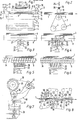
- FIG. 1 shows a plate 1 in the working gap 2 of a belt grinding unit, generally designated 3, according to a first embodiment of the invention.
- the lower part of the belt grinding unit consists of an endless grinding belt 7, which is guided over three parallel rollers 4 to 6 (FIG. 2) arranged in a triangle.
- the roller 4 serves as the drive roller, the roller 5 as the tension roller and the roller 6 as the contact roller the grinding belt 7 is guided against the lower surface of the plate 1 to be ground.
- the contact roller 6 is assigned a counter-pressure roller 8, which can be adjusted in the present preferred embodiment by means of a special parallel adjustment.
- the essence of this parallel adjustment is that the stub axles 11 and 12 of the counter-pressure roller 8, which are supported in brackets, lever arms or the like
- Counter-pressure roller 8 during the grinding process is influenced by two energy stores, such as pneumatic cylinders 17 and 18. In this way, a non-positive connection is made directly between the contact roller 6 and the counter-pressure roller 8, i.e.
- the parallel setting of the working gap 2 can be corrected by the adjusting screws 13 and 14 and production-related play or natural wear and tear in the mechanics of the parallel Adjustment can be eliminated by the pneumatic pressure acting on the counter-pressure roller 8, which in contrast to other known belt grinding units achieves an individual, uniform and high grinding accuracy.
- the counter-pressure roller 8 is now supported on the side facing away from the working gap 2 in the central region by a support roller 19 which is supported in bearings 20 and 21 of a fork 22.
- the free end of a piston rod 23 acts on this fork and thus on the support roller 19, the pressure force of which is controlled by the energy accumulator, for example a pneumatic cylinder 24, so that the line of contact between the counter-pressure roller 8 and the plate 1 is always a straight line and the working gap 2 between the counter-pressure roller 8 and the contact roller 6 is parallel.
- the support roller 19 which can be controlled in the direction of the double arrow 25 is provided with a covering 26 made of rubber, plastic or the like.
- a covering 26 made of rubber, plastic or the like.
- Such a covering serves both to reduce wear on the circumferential or working surface of the counter-pressure roller 8 and to improve the compensation of the pressure forces.
- the counter-pressure roller 8 is designed to be elastically deformable. Due to all of these features, a particularly advantageous fine adjustment can be achieved, which leads to perfectly ground plates in all respects in the continuous continuous process.
- the schematic front view according to FIG. 3 shows a counter-pressure roller 8 which, in the central region of its length, has an annular groove 27 into which an annular projection 28 of a support roller 29 engages.
- the ring-like groove 27 is dimensioned in width so that the plate 1 does not bend in this area. If only the projection 28 of the support roller 29 interacts with the groove 27 of the counter-pressure roller 8, then at the same time, wear of the jacket surface of the counter-pressure roller 8, which is in contact with the plate 1 and is thus effective, and which may have further ring-like projections and grooves, is avoided.
- the solution according to FIG. 4 largely corresponds to that according to FIG. 3, only here the number of grooves in the counter-pressure roller 8 and the number of projections of the support roller 29 are increased by two - 30, 31, 32 and 33 - so that they are even more effective Work surfaces for pressure transfer are available.
- the counter-pressure roller 8 is completely provided with ring-like projections and grooves in order to sensitively even out the pressure transmission and distribution on the plate 1.
- the projections of the support rollers 29 in the exemplary embodiments according to FIGS. 5 and 6 are adapted to the circumferential or working surfaces of the counter-pressure rollers 8 with helical grooves 34 so that only the projections of the support rollers 29 always match the outer surfaces of the projections (FIG. 5) or are in communication with the recesses (FIG. 6) of the counter-pressure rollers 8. This in turn achieves an optimum, with brush rollers and / or suction devices being unnecessary (see DE-PS 25 02 718).
- support rollers 29 designed in accordance with FIGS. 3, 4 and 5 can also advantageously be assigned from the outset or retrospectively to counterpressure rollers which, as in FIG. 1, consist, for example, of a steel cylinder with a smooth outer surface.
- FIG. 7 discloses a counter-pressure roller 35 and a support roller 36, pressure cylinders 37 and 38 as well as rockers 39 and 40 with a common pivot point 41. Characteristics essential to the invention are thereby designed to be structurally particularly simple and space-saving.
- FIG. 8 illustrates the application of the invention in a grinding machine for grinding a plate 1 on both sides by means of four belt grinding units 42, 43, 44 and 45 arranged offset from one another.
- the belt grinding units 42 and 43 are in the actual working gap contact rollers 46, 47 and grinding shoes 48, 49 and counter-pressure rollers 50, 51, 52 and 53 lying opposite them, which work together with support rollers 58, 59, 60 and 61 which can be subjected to variable pressure in the direction of the double arrows 54, 55, 56 and 57.
- the downstream belt grinding units 44 and 45 are also provided with such counter-pressure rollers and support rollers in the sense of the invention and are identified by the reference numerals 62, 63 or in the direction of the double arrows 64, 65 support rollers 66 and 67 which can be pressurized; pressure is essentially only transferred to grinding shoes 68 and 69.
Landscapes
- Engineering & Computer Science (AREA)
- Mechanical Engineering (AREA)
- Finish Polishing, Edge Sharpening, And Grinding By Specific Grinding Devices (AREA)
- Grinding Of Cylindrical And Plane Surfaces (AREA)
- Polishing Bodies And Polishing Tools (AREA)
Claims (13)
Priority Applications (1)
| Application Number | Priority Date | Filing Date | Title |
|---|---|---|---|
| AT81109482T ATE11501T1 (de) | 1980-11-03 | 1981-11-02 | Schleifmaschine fuer plattenfoermige werkstuecke. |
Applications Claiming Priority (2)
| Application Number | Priority Date | Filing Date | Title |
|---|---|---|---|
| DE3041377A DE3041377C2 (de) | 1980-11-03 | 1980-11-03 | Breitbandschleifmaschine zum Bearbeiten von Span-, Faser-, Furnier- o.dgl. Platten |
| DE3041377 | 1980-11-03 |
Publications (3)
| Publication Number | Publication Date |
|---|---|
| EP0051313A2 EP0051313A2 (fr) | 1982-05-12 |
| EP0051313A3 EP0051313A3 (en) | 1982-08-04 |
| EP0051313B1 true EP0051313B1 (fr) | 1985-01-30 |
Family
ID=6115851
Family Applications (1)
| Application Number | Title | Priority Date | Filing Date |
|---|---|---|---|
| EP81109482A Expired EP0051313B1 (fr) | 1980-11-03 | 1981-11-02 | Machine à meuler des pièces en forme de plaque |
Country Status (5)
| Country | Link |
|---|---|
| US (1) | US4569155A (fr) |
| EP (1) | EP0051313B1 (fr) |
| AT (1) | ATE11501T1 (fr) |
| CA (1) | CA1171661A (fr) |
| DE (2) | DE3041377C2 (fr) |
Families Citing this family (13)
| Publication number | Priority date | Publication date | Assignee | Title |
|---|---|---|---|---|
| DE3217935C2 (de) * | 1982-05-13 | 1984-12-13 | Küsters, Eduard, 4150 Krefeld | Bandschleifmaschine für Spanplatten u.dgl. |
| DE3316154C2 (de) * | 1983-05-03 | 1986-06-19 | Bison-Werke Bähre & Greten GmbH & Co KG, 3257 Springe | Bandschleifmaschine |
| DE4310685C2 (de) * | 1993-04-01 | 1995-01-26 | Held Kurt | Verfahren zur kontinuierlichen Direktbeschichtung von Spanplatten und Vorrichtung zur Vorbereitung der Spanplattenoberfläche |
| US5399307A (en) * | 1993-06-18 | 1995-03-21 | Dalton; Robert E. | Methods of compression molding two or more polytetrafluoroethylene resin layers |
| ES2081792T1 (es) * | 1994-05-24 | 1996-03-16 | Timesavers Inc | Topes limitadores de desplazamiento automaticamente asegurables para zapatas de presion usadas en una maquina de acabado con abrasivo. |
| RU2182073C1 (ru) * | 2001-04-06 | 2002-05-10 | Открытое акционерное общество "Всероссийский научно-исследовательский и конструкторский институт деревообрабатывающего машиностроения" | Станок шлифовальный широколенточный |
| US9108293B2 (en) * | 2012-07-30 | 2015-08-18 | Rohm And Haas Electronic Materials Cmp Holdings, Inc. | Method for chemical mechanical polishing layer pretexturing |
| CN106002553B (zh) * | 2016-05-24 | 2018-12-25 | 海门市森达装饰材料有限公司 | 一种振动磨削制备不锈钢装饰板和纹的方法 |
| CN108406951B (zh) * | 2018-03-04 | 2021-04-30 | 长乐智睿恒创节能科技有限责任公司 | 一种建筑用板材切断装置 |
| CN112720248B (zh) * | 2020-12-16 | 2022-05-03 | 浙江工业大学 | 一种具有剪切膨胀特性的高效抛光盘及其制备方法 |
| CN112872997A (zh) * | 2021-03-15 | 2021-06-01 | 湖南文理学院 | 一种翻转打磨一体式机械器件端面打磨装置 |
| CN114603877B (zh) * | 2022-03-07 | 2022-09-30 | 普洱林达木业有限责任公司 | 一种环保型复合板生产工艺及其设备 |
| CN115157035A (zh) * | 2022-07-04 | 2022-10-11 | 日氟荣高分子材料(上海)有限公司 | 一种提高磨砂棍使用寿命的控制方法 |
Citations (1)
| Publication number | Priority date | Publication date | Assignee | Title |
|---|---|---|---|---|
| DE2502718A1 (de) * | 1975-01-23 | 1976-07-29 | Baehre & Greten | Schleifmaschinen fuer platten, insbesondere holzplatten |
Family Cites Families (13)
| Publication number | Priority date | Publication date | Assignee | Title |
|---|---|---|---|---|
| US1847410A (en) * | 1929-09-10 | 1932-03-01 | Walter S Mulholland | Polishing machine |
| US1953190A (en) * | 1931-12-21 | 1934-04-03 | Paterson Alexander | Sheet rolling mill |
| US1988577A (en) * | 1933-01-04 | 1935-01-22 | Scrimgeour William | Abrading machine |
| DE701862C (de) * | 1937-05-01 | 1941-01-25 | Heinrich Koehler | Ringwalzenpresse |
| US2162279A (en) * | 1938-07-30 | 1939-06-13 | Minnesota Mining & Mfg | Method of and apparatus for grinding and polishing |
| US2479506A (en) * | 1948-01-02 | 1949-08-16 | Payton Andy Leslie | Molding sander |
| US2718827A (en) * | 1952-10-08 | 1955-09-27 | Farrel Birmingham Co Inc | Paper calender |
| US3014324A (en) * | 1957-08-05 | 1961-12-26 | Sperry Rand Corp | Hay crusher |
| US3111894A (en) * | 1962-04-17 | 1963-11-26 | West Virginia Pulp & Paper Co | Calender vibration eliminator |
| US3394501A (en) * | 1965-06-17 | 1968-07-30 | Carborundum Co | System for controlling grinding pressure |
| US3611647A (en) * | 1969-08-25 | 1971-10-12 | Evans Prod Co | Process for treating surface of plywood |
| DE2165313A1 (de) * | 1971-12-29 | 1973-07-12 | Schloemann Ag | Vorrichtung zur biegung von walzen gegen den walzdruck |
| US4178721A (en) * | 1977-12-28 | 1979-12-18 | Kimwood Corporation | Apparatus for sizing and finishing batches of lumber |
-
1980
- 1980-11-03 DE DE3041377A patent/DE3041377C2/de not_active Expired
-
1981
- 1981-11-02 EP EP81109482A patent/EP0051313B1/fr not_active Expired
- 1981-11-02 DE DE8181109482T patent/DE3168687D1/de not_active Expired
- 1981-11-02 CA CA000389194A patent/CA1171661A/fr not_active Expired
- 1981-11-02 AT AT81109482T patent/ATE11501T1/de not_active IP Right Cessation
-
1984
- 1984-04-25 US US06/603,743 patent/US4569155A/en not_active Expired - Fee Related
Patent Citations (1)
| Publication number | Priority date | Publication date | Assignee | Title |
|---|---|---|---|---|
| DE2502718A1 (de) * | 1975-01-23 | 1976-07-29 | Baehre & Greten | Schleifmaschinen fuer platten, insbesondere holzplatten |
Also Published As
| Publication number | Publication date |
|---|---|
| DE3041377A1 (de) | 1982-05-13 |
| EP0051313A2 (fr) | 1982-05-12 |
| US4569155A (en) | 1986-02-11 |
| DE3041377C2 (de) | 1982-12-30 |
| DE3168687D1 (en) | 1985-03-14 |
| EP0051313A3 (en) | 1982-08-04 |
| ATE11501T1 (de) | 1985-02-15 |
| CA1171661A (fr) | 1984-07-31 |
Similar Documents
| Publication | Publication Date | Title |
|---|---|---|
| EP0453910B1 (fr) | Chambre de racle | |
| DE69001642T2 (de) | Presse und automatische kurvenherstellungsvorrichtung dafuer. | |
| DE3041377C2 (de) | Breitbandschleifmaschine zum Bearbeiten von Span-, Faser-, Furnier- o.dgl. Platten | |
| DE3212070C2 (de) | Walzgerüst mit einer Vorrichtung zur Einhaltung der Ebenheit des gewalzten Guts | |
| DE4028740A1 (de) | Zentriervorrichtung fuer bandschleifmaschinen | |
| DE2428925A1 (de) | Trennvorrichtung mit einer aufspanneinrichtung | |
| EP0127760B1 (fr) | Ponceuse à bande | |
| DE10347548A1 (de) | Schneid-und Stanzwerk zum Auftrennen und Stanzen bahnförmiger Materialien mit unterschiedlichen Schneidsystemen | |
| DE3015874A1 (de) | Bandschleifmaschine | |
| EP0512267A2 (fr) | Laminoir | |
| DE3428039A1 (de) | Druckbalken fuer langbandschleifmaschine | |
| DE2751238C2 (de) | Vorrichtung zur Erzeugung von Nutzholz aus Rundholzstämmen | |
| DE3217935C2 (de) | Bandschleifmaschine für Spanplatten u.dgl. | |
| DE1752346A1 (de) | Bombiervorrichtung fuer Abkantpressen | |
| DE102017130128B4 (de) | Vorrichtung und Verfahren zur Herstellung einer Matte aus rieselfähigem Material auf einem luftundurchlässigen Transportband sowie Anlage zum Verpressen einer solchen Matte | |
| AT526674A4 (de) | Presse mit kompensation der stoesselverkippung | |
| DE8029277U1 (de) | Schleifmaschine fuer plattenfoermige werkstuecke | |
| DE2204216C3 (de) | Vorrichtung für das Fräsen eines Längsprofils in längsbewegte Werkstücke | |
| AT404689B (de) | Vorrichtung zur spanabhebenden bearbeitung | |
| EP1970176A1 (fr) | Presse de découpage et de cannelage | |
| EP1676696A2 (fr) | Presse fonctionnant en continu pour la fabrication de panneaux | |
| DE1729821C3 (de) | Kalander zur Herstellung von It-Dichtungsplatten | |
| DE2952012C2 (de) | Andrückvorrichtung für Kantenumleimer | |
| DE102024119652A1 (de) | Vorschubfördereinrichtung für Bandmaterial | |
| DE641584C (de) | Vorrichtung zum Schleifen der Kanten von Ofenkacheln |
Legal Events
| Date | Code | Title | Description |
|---|---|---|---|
| PUAI | Public reference made under article 153(3) epc to a published international application that has entered the european phase |
Free format text: ORIGINAL CODE: 0009012 |
|
| AK | Designated contracting states |
Designated state(s): AT BE CH DE FR GB IT SE |
|
| PUAL | Search report despatched |
Free format text: ORIGINAL CODE: 0009013 |
|
| AK | Designated contracting states |
Designated state(s): AT BE CH DE FR GB IT SE |
|
| RBV | Designated contracting states (corrected) |
Designated state(s): AT BE CH DE FR GB IT LI SE |
|
| 17P | Request for examination filed |
Effective date: 19821026 |
|
| ITF | It: translation for a ep patent filed | ||
| GRAA | (expected) grant |
Free format text: ORIGINAL CODE: 0009210 |
|
| AK | Designated contracting states |
Designated state(s): AT BE CH DE FR GB IT LI SE |
|
| REF | Corresponds to: |
Ref document number: 11501 Country of ref document: AT Date of ref document: 19850215 Kind code of ref document: T |
|
| REF | Corresponds to: |
Ref document number: 3168687 Country of ref document: DE Date of ref document: 19850314 |
|
| ET | Fr: translation filed | ||
| PLBE | No opposition filed within time limit |
Free format text: ORIGINAL CODE: 0009261 |
|
| STAA | Information on the status of an ep patent application or granted ep patent |
Free format text: STATUS: NO OPPOSITION FILED WITHIN TIME LIMIT |
|
| 26N | No opposition filed | ||
| PGFP | Annual fee paid to national office [announced via postgrant information from national office to epo] |
Ref country code: AT Payment date: 19861114 Year of fee payment: 6 |
|
| PGFP | Annual fee paid to national office [announced via postgrant information from national office to epo] |
Ref country code: DE Payment date: 19890127 Year of fee payment: 8 |
|
| PG25 | Lapsed in a contracting state [announced via postgrant information from national office to epo] |
Ref country code: GB Effective date: 19891102 Ref country code: AT Effective date: 19891102 |
|
| PG25 | Lapsed in a contracting state [announced via postgrant information from national office to epo] |
Ref country code: SE Effective date: 19891103 |
|
| PG25 | Lapsed in a contracting state [announced via postgrant information from national office to epo] |
Ref country code: LI Effective date: 19891130 Ref country code: CH Effective date: 19891130 Ref country code: BE Effective date: 19891130 |
|
| BERE | Be: lapsed |
Owner name: BISON-WERKE BAHRE & GRETEN G.M.B.H. & CO. K.G. Effective date: 19891130 |
|
| GBPC | Gb: european patent ceased through non-payment of renewal fee | ||
| PG25 | Lapsed in a contracting state [announced via postgrant information from national office to epo] |
Ref country code: FR Effective date: 19900731 |
|
| REG | Reference to a national code |
Ref country code: CH Ref legal event code: PL |
|
| PG25 | Lapsed in a contracting state [announced via postgrant information from national office to epo] |
Ref country code: DE Effective date: 19900801 |
|
| REG | Reference to a national code |
Ref country code: FR Ref legal event code: ST |
|
| EUG | Se: european patent has lapsed |
Ref document number: 81109482.0 Effective date: 19900705 |