EP0051331A1 - Dispositif à miroir pivotant - Google Patents
Dispositif à miroir pivotant Download PDFInfo
- Publication number
- EP0051331A1 EP0051331A1 EP81201166A EP81201166A EP0051331A1 EP 0051331 A1 EP0051331 A1 EP 0051331A1 EP 81201166 A EP81201166 A EP 81201166A EP 81201166 A EP81201166 A EP 81201166A EP 0051331 A1 EP0051331 A1 EP 0051331A1
- Authority
- EP
- European Patent Office
- Prior art keywords
- pivoting
- bearing support
- mirror
- bearing
- section
- Prior art date
- Legal status (The legal status is an assumption and is not a legal conclusion. Google has not performed a legal analysis and makes no representation as to the accuracy of the status listed.)
- Granted
Links
- 239000000463 material Substances 0.000 claims abstract description 4
- 239000013536 elastomeric material Substances 0.000 claims description 22
- 230000005855 radiation Effects 0.000 claims description 2
- 239000013013 elastic material Substances 0.000 abstract description 7
- 230000003287 optical effect Effects 0.000 description 10
- 229920002379 silicone rubber Polymers 0.000 description 8
- 239000004945 silicone rubber Substances 0.000 description 7
- 150000001875 compounds Chemical class 0.000 description 5
- 238000004519 manufacturing process Methods 0.000 description 4
- 238000000034 method Methods 0.000 description 2
- 238000000465 moulding Methods 0.000 description 2
- 239000004944 Liquid Silicone Rubber Substances 0.000 description 1
- 230000002411 adverse Effects 0.000 description 1
- 238000012937 correction Methods 0.000 description 1
- 230000007423 decrease Effects 0.000 description 1
- 229920001971 elastomer Polymers 0.000 description 1
- 238000005516 engineering process Methods 0.000 description 1
- 230000007613 environmental effect Effects 0.000 description 1
- 230000002349 favourable effect Effects 0.000 description 1
- 239000002184 metal Substances 0.000 description 1
- 230000007935 neutral effect Effects 0.000 description 1
- 239000004033 plastic Substances 0.000 description 1
- 229920003023 plastic Polymers 0.000 description 1
- 229920001084 poly(chloroprene) Polymers 0.000 description 1
- 230000001681 protective effect Effects 0.000 description 1
Images


Classifications
-
- G—PHYSICS
- G11—INFORMATION STORAGE
- G11B—INFORMATION STORAGE BASED ON RELATIVE MOVEMENT BETWEEN RECORD CARRIER AND TRANSDUCER
- G11B7/00—Recording or reproducing by optical means, e.g. recording using a thermal beam of optical radiation by modifying optical properties or the physical structure, reproducing using an optical beam at lower power by sensing optical properties; Record carriers therefor
- G11B7/08—Disposition or mounting of heads or light sources relatively to record carriers
- G11B7/09—Disposition or mounting of heads or light sources relatively to record carriers with provision for moving the light beam or focus plane for the purpose of maintaining alignment of the light beam relative to the record carrier during transducing operation, e.g. to compensate for surface irregularities of the latter or for track following
- G11B7/0925—Electromechanical actuators for lens positioning
-
- G—PHYSICS
- G02—OPTICS
- G02B—OPTICAL ELEMENTS, SYSTEMS OR APPARATUS
- G02B7/00—Mountings, adjusting means, or light-tight connections, for optical elements
- G02B7/18—Mountings, adjusting means, or light-tight connections, for optical elements for prisms; for mirrors
- G02B7/182—Mountings, adjusting means, or light-tight connections, for optical elements for prisms; for mirrors for mirrors
- G02B7/1821—Mountings, adjusting means, or light-tight connections, for optical elements for prisms; for mirrors for mirrors for rotating or oscillating mirrors
Definitions
- the invention relates to a pivoting-mirror device for an apparatus which scans information tracks on an information carrier with the aid of a radiation beam, which device comprises: a pivoting mirror which is pivotable about at least one pivotal axis and which has a radiation-reflecting front and, on the reverse side , a back, and a pivotal mirror bearing arrangement comprising a rigid bearing support having a first end which is situated near the back of the pivoting mirror and a second end which is remote therefrom, and an elastic bearing of an elastomeric material which is connected both to. the back of the pivoting mirror and to the bearing support, which material surrounds the first end of the bearing support and a portion of the bearing support adjacent the first end.
- a pivoting-mirror device of this type is known from United States Patent Specification No. 4,021,096.
- the mirror bearing of the pivoting-mirror device from silicone rubber, liquid silicone rubber being applied through an inlet duct in the rigid bearing support.
- the pivoting mirror and the bearing support and brought into a mutual spatial relationship which at least substantially corresponds to the spatial relationship that should exist in the finished pivoting mirror device, and a silicone rubber compound is applied through the inlet duct in a viscous mouldable condition in order to fill the space between the back of the pivoting mirror and the first end of the bearing support. Subsequently, the silicone rubber is allowed to cure.
- United States Patent Specification No. 4,129,930 proposes to manufacture the elastic bearing initially as a finished part and to affix it to the pivoting mirror at.a later stage.
- a suitable elastomeric material for a bearing manufactured in accordance with this method is, for example, chloroprene rubber. It is possible to interconnect the bearing support and the elastic bearing in a mould by means of a moulding method and during the manufacture of the elastic bearing. After the moulding operation the bearing support and the elastic bearing together constitute an easy-to-handle mounting unit.
- pivoting-mirror devices with elastic bearings In the directions in which the pivoting mirror has to be pivotable a high elasticity is required, but in all other directions of movement the bearing should have a high rigidity.
- a pivoting-mirror device In the first-mentioned United States Patent Specification 4,021,096 a pivoting-mirror device is described in which the bearing support is tubular and has an opening which faces the back of the pivoting mirror.
- the silicone rubber compound is not onoy located between the open end of the bearing support and the back of the pivoting mirror, but also partly surrounds the bearing support.
- the pivoting mirror is pivotable about any axis which is perpendicular to the optical axis of the pivoting mirror and which passes through a pivoting centre near the first end of the bearing support.
- the mirror bearing arrangement Owing to the presence of the tubular portion of the bearing support inside the part of the rubber compound which is connected to the back of the pivoting mirror, the mirror bearing arrangement is sufficiently rigid for translational movements perpendicular to the optical axis of the pivoting-mirror device. However, this adversely affects the elasticity of the pivoting bearing arrangement in the desired pivoting directions. In view of these conflicting requirements it is important to have a bearing arrangement which has a desired degree of elasticity in the desired pivoting direction or pivoting directions with a minimal volume of elastomeric elastic material.
- the pivoting mirror is only pivotable about a single axis perpendicular to the optical axis of the pivoting mirror, and the bearing support has such a shape that an elongate elastic bearing is obtained when the silicone rubber compound is applied.
- the silicone rubber is located only between the pivoting mirror and the bearing support, so that no parts of the bearing support penetrate into the elastic bearing.
- the elasticity of the pivotal bearing arrangement is high in the desired pivoting directions.
- the resistance to translational movements perpendicular to the pivotal axis is very small.
- a pivoting-mirror device of the type mentioned in the opening paragraph, comprising a mirror bearing arrangement which has a high elasticity in the desired pivoting directions and which is moreover robust and has a higher resistance to movements of the pivoting mirror in undesired directions.
- the invention is characterized in that the said portion of the bearing support which is located adjacent the first end has a cross-section in a plane perpendicular to said pivotal axis which varies from a minimum transverse dimension at the first end to a maximum transverse dimension at a location nearer the second end. Owing to the f resence of a part of the bearing support inside the elastomeric material the bearing arrangement will have the desired rigidity.
- the bearing also has a high elasticity in the desired pivoting direction or pivoting directions. As will be described in more detail hereinafter, it is possible to give the bearing a maximum elasticity for a specific volume of elastomeric material, allowance being made for the permissible load bearing capacity of the elastomeric material.
- An embodiment of the invention is characterized in that the elastomeric material surrounds the bearing support over the entire length of said portion of varying cross-section, the bearing support also being surrounded by a layer of elastomeric material at the said location where the cross-section has the maximum transverse dimension.
- This layer of elastomeric material only has a limited influence on the elasticity of the bearing and thus virtually constitutes a protective enclosure for the more inwardly disposed portion of the bearing which is of greater significance for the elastic properties of the bearing arrangement. Owing to the enclosure, environmental influences can only cause slight variations in the properties of the bearing arrangement in the course of time.
- a further embodiment of the invention is cha- racterizedin that for affixing the elastomeric material to the bearing support the bearing support has a constricted portion adjoining said portion of varying cross-section.
- This embodiment is of special significance from the point of view of manufacturing technology. The presence of the constriction prevents the elastomeric material from being drawn or slid off the bearing support.
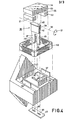
- the pivoting-mirror device shown in Fig. 1 is suitable for use in op.tical video disc players, a light beam produced by a laser being employed for scanning information tracks on a video disc.
- the device comprises a pivoting mirror 1 with a radiation-reflecting front 2 and, on the reverse side, a back 3.
- Fig. 1 shows an axis 4, hereinafter referred to as the "optical axis" of the pivoting mirror. This axis extends perpendicularly to the front 2 of the pivoting mirror and passes through the centre thereof when the pivoting mirror is in its neutral position.
- the pivoting mirror is pivotable about two pivotal axes 5 and 6 in directions which are symbolically represented by two arcuate double-headed arrows 7 and 8, and is suitable both for the correctionof errors in the track position of the optical disc and for timing error corrections.
- the axes 5 and 6 pass through a point C on the optical axis 4, which point may be regarded as the pivoting centre of the pivoting mirror.
- the pivoting mirror is pivotable about any axis through the centre C perpendicular to the optical axis 4, but the pivotal movements may practically always be regarded as combinations of pivotal movements about the axes 5 and 6.
- the pivoting-mirror device comprises a mirror bearing arrangement 2, which comprises a rigid bearing support 10.
- a first end 11 of the bearing support is disposed near the back 3 of the pivoting mirror, whilst the second end 12 is remote from the back of the pivoting mirror.
- An elastic bearing 13 is connected to the back 3 of the pivoting mirror 1 and to the bearing support 10.
- Said bearing consists of an elastomeric material, which surrounds the first end of the bearing support 10 and a portion 14 of the bearing support adjacent the first end.
- Said portion 14 of the bearing support 10 has a cross-section in planar perpendicular to the pivotal axes 5 and 6 which varies from a minimum transverse dimension at the first end 11 to a maximum transverse dimension at, a location 15 situated nearer the second end 12. (See in particular Fig. 3).
- the bearing support 10 is secured in a plastics frame 17 by means of a screw 16, which frame is in turn mounted on a metal frame carrier 18.
- the frame carrier has a threaded stud 19 secured thereto, by means of which the pivoting-mirror device can be mounted in a video disc player.
- a plurality of permanent magnets glued to the back 3, two of said magnets 20A and 21A being visible in Fig. 1.
- the permanent magnets are radially magnetized, so that their magnetic field lines extend parallel to the reflecting surface 2 of the pivoting mirror.
- control coils are arranged, three of said coils, designated 22A, 22B and 23A being shown in Fig. 1.
- the coil 22A cooperates with the permanent magnet 20A for electrically controlling pivotal movement of the pivoting mirror in the directions in dicated by the double-headed arrow 7.
- the coil 22B on the other side of the pivoting mirror cooperates with a permanent_magnet in a similar way.
- the coil 23A cooperates with the permanent magnet 21A for electrically controlling pivotal movement of the pivoting mirror in the directions indicated by the double-headed arrow 8.
- On the other side of the pivoting mirror there is arranged a similar coil and a similar permanent magnet for the same purpose.
- FIG. 1 shows a part of the pivoting-mirror device of Fig. 1 in the region of the portion 14 of the bearing support.
- This portion has a cross-section in planes containing the optical axis 4 which varies from a minimum transverse dimension at the first end 11 to a maximum transverse dimension at a location 15 situated nearer the second end 12.
- Fig. 2 shows two axes 24 and 25 which are perpendicular to each other.
- the axis 24 intersects the optical axis 4 of the pivoting-mirror device perpendicularly.
- the axis 25 intersects the axis 24 perpendicularly and is parallel to the optical axis 4.
- the axis 24 will be referred to as the X-axis, whilst the axis 25 will be referred to as the ⁇ -axis.
- the 1 -axis relates to tensile and compressive stresses occurring in the elastic material of the elastic bearing and the X-axis to the location of a point in the cross-section X-X (Fig. 3), where the bearing 13 and the back 3 of the pivoting mirror 1 are connected to each other.
- portion 14 of the bearing support which portion has the form of a truncated cone
- the stress profile from point X 2 on the X-axis no longer follows the line 27 but a horizontal line 28 between X 2 and X 3 - Since between these two values of X the circumferential surface area of the truncated cone varies linearly from a larger diameter to a smaller diameter, the length of the elastomeric material which is subjected to a tensile stress decreases linearly between X 2 and X 3 .
- FIG. 2 shows a broken line 61, which indicates the maximum permissible tensile stress in the elastomeric material.
- the location of the lines 28 and 29 above and below the X-axis respectively is determined by the magnitude of the stress ⁇ t in the elastomeric material which is considered to be permissible.
- the portions of the stress profile above and below the X-axis have substantially rectangular shapes.
- the enclosed cross-hatched areas therefore have a substantially maximum surface area. This means that a minimum amount of elastic material is employed due to the presence of the frusto conical portion 14, starting from a specific desired resistance to pivoting and a specific type of elastomeric material. This means that by approximation an optimum rigidity of the bearing exists in directions other than the desired directions.
- the embodiment of Fig. 4 concerns a pivoting-mirror device in accordance with the invention which is suitable for pivoting in the directions indicated by the double-headed arrow 31 about-only one pivotal axis 32.
- the device aomprises a pivoting mirror 33 with a radiation-reflecting front 34 and a back 35.
- the mirror bearing 36 comprises a rigid bearing support 37 having a first end 38 situated near the back 35 of the pivoting mirror 33 and an end 39 which is remote therefrom.
- an elastic bearing 40 of an elastomeric material which bearing is connected to the back 35 of the pivoting mirror and to the bearing support 37 and which material surrounds a first end 38 of the bearing support and also a portion 41 of the bearing support adjacent the first end.
- This portion of the bearing support has a cross-section in a plane perpendicular to the pivotal axis 32 which has the form of a longitudinal section of a truncated cone, specifically, a cross-section identical to the cross-section of the portion 14 of the pivotal bearing arrangement in Figs. 1 and 3. Therefore, Figs. 2 and 3 are also illustrative of the properties of the pivotal bearing arrangement 36.
- the pivoting-mirror device shown in Fig. 4 comprises a frame carrier 42 to which the bearing support 37 is secured by a plate 43.
- the bearing support has two limbs 44 and 45, which are passed through openings 46 and 47, which are bounded by a portion 48 of the frame carrier 42.
- the plate 43 has slots 49 and 50 to receive the limbs 44 and 45. After the limbs 44 and 45 have been passed through the openings 46, 47 and the slots 49, 50, the ends of the limbs are slightly twisted so that the limbs cannot be withdrawn.
- the pivoting mirror 34 carries two rod-shaped permanent magnets 51 and 52.
- a control coil 53 of substantially rectangular shape is mounted on the frame carrier 42 between the upright members 54 to 57. This guarantees a co-axial alignment of the coil 53 relative to the pivoting mirror 34.
Landscapes
- Physics & Mathematics (AREA)
- General Physics & Mathematics (AREA)
- Optics & Photonics (AREA)
- Optical Recording Or Reproduction (AREA)
- Mounting And Adjusting Of Optical Elements (AREA)
- Rear-View Mirror Devices That Are Mounted On The Exterior Of The Vehicle (AREA)
- Mechanical Optical Scanning Systems (AREA)
- Supporting Of Heads In Record-Carrier Devices (AREA)
- Mirrors, Picture Frames, Photograph Stands, And Related Fastening Devices (AREA)
- Pivots And Pivotal Connections (AREA)
Priority Applications (1)
| Application Number | Priority Date | Filing Date | Title |
|---|---|---|---|
| AT81201166T ATE8823T1 (de) | 1980-10-30 | 1981-10-22 | Schwenkspiegeleinrichtung. |
Applications Claiming Priority (2)
| Application Number | Priority Date | Filing Date | Title |
|---|---|---|---|
| NL8005948 | 1980-10-30 | ||
| NL8005948A NL8005948A (nl) | 1980-10-30 | 1980-10-30 | Zwenkspiegelinrichting. |
Publications (2)
| Publication Number | Publication Date |
|---|---|
| EP0051331A1 true EP0051331A1 (fr) | 1982-05-12 |
| EP0051331B1 EP0051331B1 (fr) | 1984-08-01 |
Family
ID=19836080
Family Applications (1)
| Application Number | Title | Priority Date | Filing Date |
|---|---|---|---|
| EP81201166A Expired EP0051331B1 (fr) | 1980-10-30 | 1981-10-22 | Dispositif à miroir pivotant |
Country Status (9)
| Country | Link |
|---|---|
| US (1) | US4376572A (fr) |
| EP (1) | EP0051331B1 (fr) |
| JP (1) | JPH0214014Y2 (fr) |
| AT (1) | ATE8823T1 (fr) |
| AU (1) | AU541896B2 (fr) |
| CA (1) | CA1160875A (fr) |
| DE (1) | DE3165257D1 (fr) |
| ES (1) | ES269689Y (fr) |
| NL (1) | NL8005948A (fr) |
Cited By (6)
| Publication number | Priority date | Publication date | Assignee | Title |
|---|---|---|---|---|
| GB2126750A (en) * | 1982-09-08 | 1984-03-28 | Pioneer Electronic Corp | Support for an oscillatable optical part |
| FR2622710A1 (fr) * | 1987-10-30 | 1989-05-05 | Sciaky Sa | Dispositif de commande en pivotement d'un outil et, notamment d'un miroir de reflexion d'un faisceau laser |
| EP0389115A1 (fr) * | 1989-03-24 | 1990-09-26 | Nicolet Instrument Corporation | Dispositif d'alignement et d'amortissement d'un miroir |
| EP0523622A3 (en) * | 1991-07-16 | 1993-12-01 | Sharp Kk | Mirror drive mechanism in optical disc player |
| EP0557443A4 (fr) * | 1990-11-15 | 1994-02-16 | Gap Technologies, Inc. | |
| EP0790512A1 (fr) * | 1996-02-13 | 1997-08-20 | EL.EN. S.p.A. | Dispositif et procédé de déflexion d'un faisceau laser par un miroir unique |
Families Citing this family (7)
| Publication number | Priority date | Publication date | Assignee | Title |
|---|---|---|---|---|
| US4616226A (en) * | 1982-11-12 | 1986-10-07 | The Garrett Corporation | Peripheral vision artificial horizon device and associated methods |
| US4743903A (en) * | 1982-11-12 | 1988-05-10 | The Garrett Corporation | Peripheral vision artificial horizon device and associated methods |
| US5040860A (en) * | 1990-08-29 | 1991-08-20 | Litton Systems, Inc. | Momentum-balance mechanism for use with a scan mirror or other component |
| US5239361A (en) * | 1991-10-25 | 1993-08-24 | Nicolet Instrument Corporation | Dynamic mirror alignment device for the interferometer of an infrared spectrometer |
| US5883712A (en) * | 1997-05-21 | 1999-03-16 | Nicolet Instrument Corporation | Interferometer of an infrared spectrometer with dynamic moving mirror alignment |
| US7643196B2 (en) * | 2005-12-16 | 2010-01-05 | The Charles Stark Draper Laboratory, Inc. | Systems, methods and devices for actuating a moveable miniature platform |
| US7797252B2 (en) * | 2006-10-20 | 2010-09-14 | Target Brands, Inc. | Service plan product and associated system |
Citations (4)
| Publication number | Priority date | Publication date | Assignee | Title |
|---|---|---|---|---|
| GB337084A (en) * | 1929-07-11 | 1930-10-30 | Selenophon Licht & Tonbildges | Damping device for oscillographs, particularly for photographically recording sound |
| DE660974C (de) * | 1933-02-15 | 1938-06-07 | Telefunken Gmbh | Daempfungseinrichtung fuer Oszillographen |
| CH354117A (de) * | 1957-09-25 | 1961-05-15 | Philips Ag | Vorrichtung zur Verschwenkung mindestens einer spiegelnden Fläche nach Massgabe mindestens einer elektrischen Grösse |
| US4021096A (en) * | 1975-10-20 | 1977-05-03 | U.S. Philips Corporation | Electrodynamically controllable pivoting mirror device |
Family Cites Families (1)
| Publication number | Priority date | Publication date | Assignee | Title |
|---|---|---|---|---|
| ES465879A1 (es) * | 1977-01-13 | 1979-01-01 | Philips Nv | Un metodo de fabricar un dispositivo de espejo pivotante electricamente controlable |
-
1980
- 1980-10-30 NL NL8005948A patent/NL8005948A/nl not_active Application Discontinuation
-
1981
- 1981-01-29 US US06/229,419 patent/US4376572A/en not_active Expired - Fee Related
- 1981-10-22 EP EP81201166A patent/EP0051331B1/fr not_active Expired
- 1981-10-22 AT AT81201166T patent/ATE8823T1/de not_active IP Right Cessation
- 1981-10-22 DE DE8181201166T patent/DE3165257D1/de not_active Expired
- 1981-10-27 JP JP1981159149U patent/JPH0214014Y2/ja not_active Expired
- 1981-10-28 AU AU76892/81A patent/AU541896B2/en not_active Ceased
- 1981-10-28 ES ES1981269689U patent/ES269689Y/es not_active Expired
- 1981-10-29 CA CA000389037A patent/CA1160875A/fr not_active Expired
Patent Citations (4)
| Publication number | Priority date | Publication date | Assignee | Title |
|---|---|---|---|---|
| GB337084A (en) * | 1929-07-11 | 1930-10-30 | Selenophon Licht & Tonbildges | Damping device for oscillographs, particularly for photographically recording sound |
| DE660974C (de) * | 1933-02-15 | 1938-06-07 | Telefunken Gmbh | Daempfungseinrichtung fuer Oszillographen |
| CH354117A (de) * | 1957-09-25 | 1961-05-15 | Philips Ag | Vorrichtung zur Verschwenkung mindestens einer spiegelnden Fläche nach Massgabe mindestens einer elektrischen Grösse |
| US4021096A (en) * | 1975-10-20 | 1977-05-03 | U.S. Philips Corporation | Electrodynamically controllable pivoting mirror device |
Cited By (8)
| Publication number | Priority date | Publication date | Assignee | Title |
|---|---|---|---|---|
| GB2126750A (en) * | 1982-09-08 | 1984-03-28 | Pioneer Electronic Corp | Support for an oscillatable optical part |
| FR2622710A1 (fr) * | 1987-10-30 | 1989-05-05 | Sciaky Sa | Dispositif de commande en pivotement d'un outil et, notamment d'un miroir de reflexion d'un faisceau laser |
| EP0389115A1 (fr) * | 1989-03-24 | 1990-09-26 | Nicolet Instrument Corporation | Dispositif d'alignement et d'amortissement d'un miroir |
| US5276545A (en) * | 1989-03-24 | 1994-01-04 | Nicolet Instrument Corporation | Mirror alignment and damping device |
| EP0557443A4 (fr) * | 1990-11-15 | 1994-02-16 | Gap Technologies, Inc. | |
| EP0523622A3 (en) * | 1991-07-16 | 1993-12-01 | Sharp Kk | Mirror drive mechanism in optical disc player |
| EP0790512A1 (fr) * | 1996-02-13 | 1997-08-20 | EL.EN. S.p.A. | Dispositif et procédé de déflexion d'un faisceau laser par un miroir unique |
| US5754327A (en) * | 1996-02-13 | 1998-05-19 | El.En. S.P.A. | Device and method for deflecting a laser beam by means of a single mirror |
Also Published As
| Publication number | Publication date |
|---|---|
| EP0051331B1 (fr) | 1984-08-01 |
| AU541896B2 (en) | 1985-01-24 |
| US4376572A (en) | 1983-03-15 |
| NL8005948A (nl) | 1982-05-17 |
| JPS5791142U (fr) | 1982-06-04 |
| DE3165257D1 (en) | 1984-09-06 |
| AU7689281A (en) | 1982-05-06 |
| JPH0214014Y2 (fr) | 1990-04-17 |
| ES269689U (es) | 1983-07-01 |
| ES269689Y (es) | 1984-01-16 |
| ATE8823T1 (de) | 1984-08-15 |
| CA1160875A (fr) | 1984-01-24 |
Similar Documents
| Publication | Publication Date | Title |
|---|---|---|
| EP0051331B1 (fr) | Dispositif à miroir pivotant | |
| KR930000352B1 (ko) | 전자 광학 장치 | |
| CA1070998A (fr) | Miroir pivotant a commande electrodynamique | |
| US5483608A (en) | Optical switch for switching plural optical fibers | |
| US5719834A (en) | Objective lens driving apparatus and method including visco-elastic support for a magnetic circuit which allows translation of the magnetic circuit without pivoting or rotating there of | |
| CA1226125A (fr) | Methode et moyen d'alignement d'un dispositif optique | |
| US5313334A (en) | Objective lens moving actuator | |
| US6181670B1 (en) | Objective lens mounting apparatus and objective lens driving apparatus | |
| US7286448B2 (en) | Actuator for use in pickup device in reducing lens distortion | |
| GB1597935A (en) | Electrically controllable pivoting mirror arrangement | |
| US5074638A (en) | Method for joining optical fibers at the fiber interface of a beveled angle fiber optic connector | |
| EP0176127A1 (fr) | Support de l'objectif pour un dispositif électrodynamique pour enregistrer sur et/ou balayer des disques optiques par un faisceau lumineux et procédé pour fabriquer un tel support de l'objectif | |
| JP2001222836A (ja) | ピックアップ | |
| US4488789A (en) | Electromagnetically deflectable device | |
| US4877302A (en) | Plug connector for the ends of two light waveguides | |
| JPH0345366B2 (fr) | ||
| JPH0349137B2 (fr) | ||
| CA2057808A1 (fr) | Connecteur de fibres optiques a extremite chanfreinee | |
| US5428589A (en) | Apparatus and method for an electromagnetic actuator with two orthogonal axes of motion | |
| US5367511A (en) | Scanning lens mount using deflection and twisting for separate movements | |
| KR100466184B1 (ko) | 2축액튜에이터,광학픽업,광디스크드라이브장치 | |
| JPH11232670A (ja) | 光学式ピックアップ | |
| JP2521564Y2 (ja) | 光学式ピックアップのアクチュエータ | |
| JP2007298421A (ja) | 光学系駆動装置 | |
| JPH05314511A (ja) | 対物レンズ駆動装置 |
Legal Events
| Date | Code | Title | Description |
|---|---|---|---|
| PUAI | Public reference made under article 153(3) epc to a published international application that has entered the european phase |
Free format text: ORIGINAL CODE: 0009012 |
|
| AK | Designated contracting states |
Designated state(s): AT DE FR GB IT NL |
|
| 17P | Request for examination filed |
Effective date: 19820616 |
|
| RAP1 | Party data changed (applicant data changed or rights of an application transferred) |
Owner name: N.V. PHILIPS' GLOEILAMPENFABRIEKEN |
|
| ITF | It: translation for a ep patent filed | ||
| GRAA | (expected) grant |
Free format text: ORIGINAL CODE: 0009210 |
|
| AK | Designated contracting states |
Designated state(s): AT DE FR GB IT NL |
|
| REF | Corresponds to: |
Ref document number: 8823 Country of ref document: AT Date of ref document: 19840815 Kind code of ref document: T |
|
| REF | Corresponds to: |
Ref document number: 3165257 Country of ref document: DE Date of ref document: 19840906 |
|
| ET | Fr: translation filed | ||
| PLBE | No opposition filed within time limit |
Free format text: ORIGINAL CODE: 0009261 |
|
| STAA | Information on the status of an ep patent application or granted ep patent |
Free format text: STATUS: NO OPPOSITION FILED WITHIN TIME LIMIT |
|
| 26N | No opposition filed | ||
| PGFP | Annual fee paid to national office [announced via postgrant information from national office to epo] |
Ref country code: AT Payment date: 19861016 Year of fee payment: 6 |
|
| PGFP | Annual fee paid to national office [announced via postgrant information from national office to epo] |
Ref country code: NL Payment date: 19871031 Year of fee payment: 7 |
|
| PG25 | Lapsed in a contracting state [announced via postgrant information from national office to epo] |
Ref country code: AT Effective date: 19881022 |
|
| PG25 | Lapsed in a contracting state [announced via postgrant information from national office to epo] |
Ref country code: NL Effective date: 19890501 |
|
| NLV4 | Nl: lapsed or anulled due to non-payment of the annual fee | ||
| PGFP | Annual fee paid to national office [announced via postgrant information from national office to epo] |
Ref country code: DE Payment date: 19891215 Year of fee payment: 9 |
|
| PGFP | Annual fee paid to national office [announced via postgrant information from national office to epo] |
Ref country code: GB Payment date: 19901001 Year of fee payment: 10 |
|
| PGFP | Annual fee paid to national office [announced via postgrant information from national office to epo] |
Ref country code: FR Payment date: 19901023 Year of fee payment: 10 |
|
| ITTA | It: last paid annual fee | ||
| PG25 | Lapsed in a contracting state [announced via postgrant information from national office to epo] |
Ref country code: DE Effective date: 19910702 |
|
| PG25 | Lapsed in a contracting state [announced via postgrant information from national office to epo] |
Ref country code: GB Effective date: 19911022 |
|
| GBPC | Gb: european patent ceased through non-payment of renewal fee | ||
| PG25 | Lapsed in a contracting state [announced via postgrant information from national office to epo] |
Ref country code: FR Effective date: 19920630 |
|
| REG | Reference to a national code |
Ref country code: FR Ref legal event code: ST |