EP0051453A1 - Steuergerät zur Spindelorientierung - Google Patents
Steuergerät zur Spindelorientierung Download PDFInfo
- Publication number
- EP0051453A1 EP0051453A1 EP81305125A EP81305125A EP0051453A1 EP 0051453 A1 EP0051453 A1 EP 0051453A1 EP 81305125 A EP81305125 A EP 81305125A EP 81305125 A EP81305125 A EP 81305125A EP 0051453 A1 EP0051453 A1 EP 0051453A1
- Authority
- EP
- European Patent Office
- Prior art keywords
- spindle
- signal
- speed
- circuit
- magnetic body
- Prior art date
- Legal status (The legal status is an assumption and is not a legal conclusion. Google has not performed a legal analysis and makes no representation as to the accuracy of the status listed.)
- Granted
Links
Images


Classifications
-
- G—PHYSICS
- G05—CONTROLLING; REGULATING
- G05B—CONTROL OR REGULATING SYSTEMS IN GENERAL; FUNCTIONAL ELEMENTS OF SUCH SYSTEMS; MONITORING OR TESTING ARRANGEMENTS FOR SUCH SYSTEMS OR ELEMENTS
- G05B19/00—Program-control systems
- G05B19/02—Program-control systems electric
- G05B19/18—Numerical control [NC], i.e. automatically operating machines, in particular machine tools, e.g. in a manufacturing environment, so as to execute positioning, movement or co-ordinated operations by means of program data in numerical form
- G05B19/19—Numerical control [NC], i.e. automatically operating machines, in particular machine tools, e.g. in a manufacturing environment, so as to execute positioning, movement or co-ordinated operations by means of program data in numerical form characterised by positioning or contouring control systems, e.g. to control position from one programmed point to another or to control movement along a programmed continuous path
- G05B19/39—Numerical control [NC], i.e. automatically operating machines, in particular machine tools, e.g. in a manufacturing environment, so as to execute positioning, movement or co-ordinated operations by means of program data in numerical form characterised by positioning or contouring control systems, e.g. to control position from one programmed point to another or to control movement along a programmed continuous path using a combination of the means covered by at least two of the preceding groups G05B19/21, G05B19/27 and G05B19/33
-
- G—PHYSICS
- G05—CONTROLLING; REGULATING
- G05B—CONTROL OR REGULATING SYSTEMS IN GENERAL; FUNCTIONAL ELEMENTS OF SUCH SYSTEMS; MONITORING OR TESTING ARRANGEMENTS FOR SUCH SYSTEMS OR ELEMENTS
- G05B11/00—Automatic controllers
- G05B11/01—Automatic controllers electric
- G05B11/14—Automatic controllers electric in which the output signal represents a discontinuous function of the deviation from the desired value, i.e. discontinuous controllers
- G05B11/18—Multi-step controllers
-
- G—PHYSICS
- G05—CONTROLLING; REGULATING
- G05B—CONTROL OR REGULATING SYSTEMS IN GENERAL; FUNCTIONAL ELEMENTS OF SUCH SYSTEMS; MONITORING OR TESTING ARRANGEMENTS FOR SUCH SYSTEMS OR ELEMENTS
- G05B2219/00—Program-control systems
- G05B2219/30—Nc systems
- G05B2219/49—Nc machine tool, till multiple
- G05B2219/49273—Switch between continuous drive and index or stop mode
Definitions
- This invention relates to a spindle orientation control apparatus which employs a magnetic sensor and, but not exclusively more particularly/ to a spindle orientation control system which has a simplified magnetic sensor contruction, and which enables the spindle to be stopped at a predetermined orientation with a high degree of accuracy.
- the invention also relates to the magnetic sensor itself.
- Machine tools with an automatic tool change function are well known in the art. These are machine tools that perform machining work automatically while various tools are changed, also automatically. In order to mate a desired tool with the machine tool spindle in a smooth manner, it is necessary to stop a specified portion of the spindle at a predetermined commanded angular position with a high degree of accuracy. The same is true also in boring- type machine tools in order to insert a boring rod into a hole previously drilled in a workpiece. Thus the need to stop a specified portion of a spindle at a predetermined angular position or orientation in accurate fashion is quite common in mechanical machining operations.
- a spindle orientation control apparatus which comprises:
- a preferred embodiment of the present invention provides a spindle orientation control system which is capable of stopping a specified portion of a spindle at a predetermined angular position with a high accuracy through purely electrical means, which allows the use of a contactless magnetic sensor as position deviation signal generating means, and which simplifies the construction of the magnetic sensor.
- a preferred embodiment provides a spindle orientation control apparatus in which the angular position or orientation of a spindle is sensed by means composed of a magnetic body provided on a specified portion of the spindle, and a sensor provided to confront the magnetic body, the spindle drive motor being brought to a stop gently at a predetermined orientation by the gradually diminishing output of the sensing means.
- Hunting and overshoot may be prevented when stopping the spindle at a predetermined orientation, by adjusting the gain of a circuit for producing a command signal supplied to a speed control circuit, said adjustment being made in accordance with the reduction ratio of gears coupling the spindle to the spindle drive motor.
- a magnetic sensor for use in a spindle orientation control apparatus, the sensor comprising a magnetic body formed in such a manner that its magnetic strength varies along one of its dimensions, and a sensing circuit comprising two saturable reactors on which coils are wound in a cumulative and differential manner respectively.
- a speed command circuit 1 which produces a speed command signal CV
- an orientation command circuit 2 which produces an orientation command signal ORCM.
- a speed control circuit 3 is provided.
- the adder 3a is adapted to deliver a difference voltage (Speed deviation) between the commanded speed CV and the actual motor speed AV in a speed control mode, and to deliver a difference voltage between an orientation or rotational position deviation signal RPD and the actual speed signal AV.
- the phase compensating circuit 3b subjects the output voltage of the adder 3a to a phase compensation by advancing or retarding its phase.
- the voltage-to-phase converter 3c controls the firing angle of each thyristor in the thyristor circuit 3d in accordance with the output voltage of the phase compensating circuit 3b.
- the thyristor circuit 3d operates in accordance with the controlled firing pulses of its thyristors to vary the value of a voltage applied_to a DC motor 4, thereby to regulate the speed at which the motor 4 rotates.
- a tachometer 5 generates a voltage in accordance with the motor speed.
- Numeral 6 denotes a spindle mechanism, 7 a spindle, 8 a tool and 9 a gear train for transmitting the rotational motion of the DC motor 4 to the spindle 7.
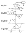
- a magnetic sensor 10 which, as shown in Fig. 3, comprises a magnetic body 10a, a sensing circuit 10b, and an amplifier 10c. The magnetic sensor 10 will be described in detail below.
- an orientation control circuit 11 includes a rotational position deviation signal generating circuit 11a which produces a rotational position deviation signal RPD of a voltage level in accordance with a position deviation, as well as an orientation end signal ORDEN, and a loop changeover circuit 11b for actuating a loop change over switch 12 in response to an orientation command from the orientation command circuit 2.
- the magnetic body 10a is attached to the spindle at an angular position thereof corresponding to the specified portion which is to be stopped at the commanded orientation.
- the magnetic body 10a has magnets 10a', 10a", possessed of a triangular cross-section, mounted and arranged in such a manner that the strength of the magnetic field chnages from S to N in the direction of spindle rotation, i.e., in the direction of the arrow.
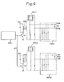
- the sensing circuit 10b is mounted on a stationary portion of the machine so as to confront the magnetic body .10a, and includes two saturable reactors SRA1, SRA2 (Fig. 4) provided in a case.
- Each saturable reactor SRA1, SRA2 has coils wound on a core, and the coil terminals are differentially and cumulatively connected to produce a cumulative output signal and a differential output signal.
- a signal MS 1 is obtained from one coil, and a signal MS 2 from the other coil.
- the cumulatively connected coils provide a cumulative output signal DV, having a substantially S-shaped form as depicted in (C) of Fig. 3, and the differentially connected coils provide a differential output signal ASV which is illustrated in (D) of Fig. 3.
- the magnetic body 10a is attached to the specified portion of the spindle, and the sensing circuit 10b is fixed at a stationary position corresponding to the predetermined angular position or orientation. Therefore, the cumulative output signal DV is a voltage waveform having a value of zero volt when the center line of the magnetic body 10a coincides with the center line of the sensing circuit 10b. At such time the waveform is positive on one side of the zero value and-negative on the other side; that is, the waveform completely crosses the zero level.
- the cumulative output signal DV has a shape which conforms to the deviation from said orientation. Accordingly, the signal DV will be referred to as a fine position deviation signal hereinafter.
- the differential output signal ASV is positive in the vicinity of the predetermined orientation and is referred to as an approach signal hereinafter.
- the sensing circuit 10b is composed of a blocking oscillator OSC for generating a high-frequency (100kHz) pulsed signal HFP, switching transistors TR 1 , TR 2 , isolating transformers ITR 1 , ITR 2 , and rectifiers HWR 1 , HWR Z .
- the saturable reactors SRA are excited by the high-frequency pulsed signal HFP through the isolating transformers ITR 1 , ITR 2 .
- the fine position deviation signal DV which conforms to the angular position of the magnetic body 10a, and the approach signal ASV, are obtained across the terminals MSA, MSB and across the terminals LSA, LSB, respectively.
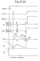
- the position deviation signal generating circuit 11a shown in Fig. 1 will now be described in conjunction with the waveforms depicted in (A) of Fig. 2.
- the magnetic sensor produces the fine position deviation signal DV and the approach signal ASV, both of which are applied to the position deviation signal generating circuit 11a.
- the signal AV indicative of the actual speed of the DC motor 4 also enters the circuit 11a from the tachometer 5 and is integrated within the circuit 11a.
- the result of-the integration operation is subtracted from an initially set voltage ISV which will be described below (ISV having a value -V i during . forward spindle rotation, and a value +V i during reverse spindle rotation).
- the result of the subtraction operation is a coarse position deviation signal CPD.
- the position deviation signal generating circuit 11a is adapted to form the constant initially set voltage ISV and a bias signal BIS.
- the voltage value V i of the voltage ISV is set so as to be equal to a position deviation voltage which corresponds to one revolution (360°) of the spindle.
- the position deviation signal generating circuit 11a produces the initially set voltage ISV from the time the orientation command signal ORCM is generated until the time that the spindle initially reaches the predetermined orientation. It will be assumed here that the value of ISV is -V i , i.e., that the orientation operation is performed while the spindle is rotating in the forward direction.
- the coarse deviation signal CPD (negative polarity) is produced until the magnetic body 10a reaches a first proximal region AR1
- the fine position deviation signal DV is produced after the magnetic body 10a has entered the region AR 2 .
- the position deviation signal RPD has a negative polarity and the overall shape shown in (A) of Fig. 2 when the orientation operation is executed during forward spindle rotation. It should be noted that the component consisting of the bias signal waveform BIS can be eliminated from the signal RPD if so desired by setting 62 equal to 8 1 .
- ISV takes on the value +V i
- the coarse position deviation signal takes on a positive polarity represented by the CPD component having the positive polarity
- BIS takes on the value +B .
- the position deviation signal RPD has a positive polarity and the overall shape shown on the right-hand side of Fig. 2(A)
- the changeover switch 12 is connected to the a side in Fig. 1, thereby forming a speed control loop.
- the adder 3a receives the speed command signal CV from the speed command circuit 1 and the actual speed signal AV from the tachometer 5, and responds by delivering a speed deviation voltage.
- the voltage-to-phase converter 3c controls the firing angle of the thyristors in the thyristor circuit 3d in accordance with the speed deviation voltage, the thyristor circuit 3d thereby regulating the voltage applied to the DC motor 4.
- the speed control loop regulates the speed of the motor 4 in such a manner that the speed deviation approaches zero, the motor, namely the spindle, thereby being rotated at the command speed during operation in the speed control mode.
- a control device such as a numerical control device instructs the orientation command circuit 2 to apply the orientation command signal ORCM to the loop changeover circuit 11b at time t , the speed command signal CV becoming zero at this time.
- the actual speed AV consequently decreases and reaches zero (or a predetermined constant value) at time t 1 .
- a pulse signal VZR indicative of zero speed is generated within the position deviation signal generating circuit 11a, and causes the loop changeover circuit 11b to change the switch 12 over to the b side, so that circuit operation is shifted from the speed control to the position control mode.
- the spindle In response to this signal the spindle begins to be rotated again so that the signal AV indicative of actual spindle speed rises to assume the value V . .
- the position deviation signal generating circuit 11a As the magnetic body 10a (Fig. 3) on the spindle continues to rotate and reaches the predetermined angular position for the first time (time t 2 ), the position deviation signal generating circuit 11a generates the coarse position deviation signal CPD.
- the position deviation signal generating circuit 11a produces the bias signal BIS.
- the circuit 11a produces the fine position deviation signal DV.
- the signal DV reaches zero, namely when the magnetic.body 10a (the specified portion of the spindle) is confronting the saturable reactor SRA head-on, the orientation operation for stopping the spindle at the predetermined angular position is complete.
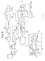
- Fig. 5 The details of the position deviation signal generating circuit 11a are shown in Fig. 5 which will now be described with reference to the timing chart shown in Fig. 6. Portions in Fig. 5 identical with those in Fig. 1 are denoted by like reference characters and are not described again here.
- a circuit 101 is provided to form the initially set voltage ISV and the bias signal BIS, to integrate the actual voltage signal AV, and to subtract the integrated output (indicative of the present position of the spindle) from the initially set voltage ISV.
- a switch SW is connected to -15 volts when the spindle is at rest or when the spindle is rotating in the forward direction, or to +15 volts when the spindle is rotating in the reverse direction.
- the selected voltage is fed through an amplifier AMP 1 and a switch S 9 to charge a capacitor C, the charged voltage serving as the voltage -Vi or +V . of the initially set voltage ISV.
- Numerals 102, 103 denote changeover circuits for switching gain in accordance with gear ratio. These circuits are operable to set the gain of the position control loop high when the gears between the DC motor 4 and spindle 7 are set low (reduction ratio is high), and to set the gain low when the gears are set high (reduction ratio low), that is, to set the gain low in comparison to the gain for the high reduction ratio. More specifically, when the reduction ratio is high, switches S 7 , S 2 are closed to raise the gain, and when the reduction ratio is low, switches S 8 , S 3 are closed to lower the gain. This eliminates spindle hunting and overshoot when stopping the spindle at the predetermined angular position, and permits the spindlc orientation operation to be completed in less time regardless of the size of the reduction ratio.
- Denoted at numeral 104 is a well-known absolute value circuit which takes the absolute value of the output from circuit 101.
- a comparator 105 detects whether or not the coarse position deviation signal CPD has fallen below a predetermined level, and produces a signal NRPS which indicates that the predetermined portion of the spindle (the magnetic body 10a) has approached the first proximal region AR 1 .
- the signal NRPS closes the switches S 9 , S 10'
- a gain adjustment circuit 106 adjusts the gain in accordance with the gap between the magnetic body 10a and the sensing circuit 10b, and produces the fine position deviation signal DV 2 having a prescribed slope.
- a slicing circuit 107 slices the approach signal ASV at a predetermined level and produces a signal LS which indicates that the magnetic body 10a has reached the area closely adjacent the predetermined angular position.
- the signal LS opens the switches S 5 , S6 and closes the switch S 4 .
- the fine position deviation signal DV is delivered as the position deviation signal RPD.
- a forward-reverse changeover circuit 108 has its switch S 5 closed when the spindle is controlled for orientation by rotating it in the forward direction,.and its switch S 6 closed when the spindle is controlled for orientation by rotating it in the reverse direction.
- An "in-position" signal generating circuit 109 comprising a comparator, monitors the fine position deviation signal DV and generates the in-position signal INPOS when the spindle is within the range of the predetermined angular position.
- the signal INPOS is sent to the numerical control device as a signal indicating completion of the orientation operation.
- Comparators 110, 111 monitor the fine position deviation signal DV and produce signals NEG, POS upon detecting whether the spindle is approaching the predetermined angular position while rotating in the'reverse direction (signal NEG at logical "1"), or while rotating in the forward direction (signal POS at logical "1"), respectively. Either switch S 5 or switch S 6 will close in response to the signals NEG, POS.
- a waveform synthesizing circuit 112 delivers either the fine position deviation signal or the coarse position deviation signal in accordance with the open or closed states of the switches S 4 , S 5 or S 6 .
- the motor In response to the voltage ISV, the motor begins rotating again so that the spindle is rotated and reaches the predetermined angular position for the first time (i.e., the signal LS is a "1", and the in-position signal INPOS is a "1").
- the signal LS is a "1”
- the in-position signal INPOS is a "1”
- switch S 9 is opened and one of the switches S 7 , S 8 is closed in accordance with the low/ high setting of the gears. Therefore the coarse position deviation signal CPD is obtained from the output terminal OUT.
- the comparator 105 issues the signal NRPS (logical "1"), whereby the switches S 9 , S 10 are closed.
- the bias signal of the prescribed level is delivered from the output terminal OUT.
- the signal LS goes to the "1" level, switches S 5 , S 6 are opened, and switch S 4 is closed._
- the fine position deviation signal DV is delivered from the output terminal OUT.
- spindle orientation control operation need not be executed after the speed drops to zero, as in the above case. It is possible to execute the operation after a value other than zero has been attained.
- a spindle can be stopped at a predetermined angular position with a high accuracy without relying upon contacting parts such as a mechanical brake.
- a highly accurate magnetic sensor is provided and adapted to produce a fine position deviation signal when a specified portion of the spindle has reached the vicinity of the predetermined angular position, whereby an extremely high accuracy in the order of from +0.03° to +0.05° can be
Landscapes
- Engineering & Computer Science (AREA)
- Physics & Mathematics (AREA)
- General Physics & Mathematics (AREA)
- Automation & Control Theory (AREA)
- Human Computer Interaction (AREA)
- Manufacturing & Machinery (AREA)
- Automatic Control Of Machine Tools (AREA)
- Control Of Position Or Direction (AREA)
- Stopping Of Electric Motors (AREA)
Applications Claiming Priority (2)
| Application Number | Priority Date | Filing Date | Title |
|---|---|---|---|
| JP55152702A JPS5775753A (en) | 1980-10-30 | 1980-10-30 | Main shaft rotary position control system |
| JP152702/80 | 1980-10-30 |
Publications (2)
| Publication Number | Publication Date |
|---|---|
| EP0051453A1 true EP0051453A1 (de) | 1982-05-12 |
| EP0051453B1 EP0051453B1 (de) | 1986-01-15 |
Family
ID=15546273
Family Applications (1)
| Application Number | Title | Priority Date | Filing Date |
|---|---|---|---|
| EP81305125A Expired EP0051453B1 (de) | 1980-10-30 | 1981-10-29 | Steuergerät zur Spindelorientierung |
Country Status (5)
| Country | Link |
|---|---|
| US (1) | US4450393A (de) |
| EP (1) | EP0051453B1 (de) |
| JP (1) | JPS5775753A (de) |
| KR (1) | KR880000420B1 (de) |
| DE (1) | DE3173530D1 (de) |
Cited By (4)
| Publication number | Priority date | Publication date | Assignee | Title |
|---|---|---|---|---|
| DE3306555A1 (de) * | 1983-02-25 | 1984-08-30 | Brown, Boveri & Cie Ag, 6800 Mannheim | Regeleinrichtung fuer werkzeugmaschinen mit einer spindel |
| EP0219017A1 (de) * | 1985-10-07 | 1987-04-22 | Maschinenfabrik Rieter Ag | Positioniersysteme |
| US4703617A (en) * | 1983-05-24 | 1987-11-03 | Rieter Machine Works, Ltd. | Automat location system |
| EP0242940A3 (en) * | 1986-01-28 | 1988-11-23 | Macome Corporation | Magnetic detector |
Families Citing this family (11)
| Publication number | Priority date | Publication date | Assignee | Title |
|---|---|---|---|---|
| JPS6198186A (ja) * | 1984-10-17 | 1986-05-16 | Mitsubishi Electric Corp | インバ−タ装置の位置決め割り出し制御方式 |
| JPH0756608B2 (ja) * | 1986-03-24 | 1995-06-14 | キヤノン株式会社 | 位置決め制御装置 |
| JPH01174283A (ja) * | 1987-12-28 | 1989-07-10 | Fanuc Ltd | 主軸オリエンテーション制御装置 |
| JP2692274B2 (ja) * | 1989-06-22 | 1997-12-17 | 三菱電機株式会社 | 主軸位置・速度制御装置 |
| US5093610A (en) * | 1990-02-12 | 1992-03-03 | Abb Robotics Inc. | Apparatus for absolute position measurement |
| JPH04294406A (ja) * | 1991-03-22 | 1992-10-19 | Kobe Steel Ltd | ロボットの回転位置検出装置 |
| JPH05336789A (ja) * | 1992-06-01 | 1993-12-17 | Fanuc Ltd | モータの制御方式 |
| JP2002199767A (ja) * | 2000-12-27 | 2002-07-12 | Aisin Seiki Co Ltd | 外乱補償制御装置 |
| US20030117132A1 (en) * | 2001-12-21 | 2003-06-26 | Gunnar Klinghult | Contactless sensing input device |
| US6802378B2 (en) | 2002-12-19 | 2004-10-12 | Noble Engineering And Development, Ltd. | Method of and apparatus for directional drilling |
| US9231500B2 (en) * | 2013-01-30 | 2016-01-05 | Nidec Motor Corporation | Sensorless motor braking system |
Citations (5)
| Publication number | Priority date | Publication date | Assignee | Title |
|---|---|---|---|---|
| DE919757C (de) * | 1942-05-31 | 1954-11-04 | Siemens & Halseke Ag | Elektrischer Geber fuer Fernanzeige- und Fernsteuereinrichtungen |
| GB839126A (en) * | 1955-12-23 | 1960-06-29 | North American Aviation Inc | Improvements in or relating to digital-analog servo circuit |
| GB895048A (en) * | 1958-09-24 | 1962-04-26 | Genevoise Instr Physique | Control device for the setting in exact position of a movable member |
| FR2402514A1 (fr) * | 1977-09-08 | 1979-04-06 | Fujitsu Fanuc Ltd | Dispositif de commande de l'orientation de la broche d'une machine-outil |
| EP0028079A2 (de) * | 1979-10-09 | 1981-05-06 | Fanuc Ltd. | Steuersystem zum Anhalten der Spindel in einer vorbestimmten Drehposition |
Family Cites Families (2)
| Publication number | Priority date | Publication date | Assignee | Title |
|---|---|---|---|---|
| US3824891A (en) * | 1973-05-11 | 1974-07-23 | Litton Industrial Products | Machine tool |
| US4350939A (en) * | 1980-10-03 | 1982-09-21 | The Bendix Corporation | Spindle orient device |
-
1980
- 1980-10-30 JP JP55152702A patent/JPS5775753A/ja active Granted
-
1981
- 1981-10-28 KR KR1019810004117A patent/KR880000420B1/ko not_active Expired
- 1981-10-29 DE DE8181305125T patent/DE3173530D1/de not_active Expired
- 1981-10-29 EP EP81305125A patent/EP0051453B1/de not_active Expired
- 1981-10-30 US US06/316,762 patent/US4450393A/en not_active Expired - Lifetime
Patent Citations (6)
| Publication number | Priority date | Publication date | Assignee | Title |
|---|---|---|---|---|
| DE919757C (de) * | 1942-05-31 | 1954-11-04 | Siemens & Halseke Ag | Elektrischer Geber fuer Fernanzeige- und Fernsteuereinrichtungen |
| GB839126A (en) * | 1955-12-23 | 1960-06-29 | North American Aviation Inc | Improvements in or relating to digital-analog servo circuit |
| GB895048A (en) * | 1958-09-24 | 1962-04-26 | Genevoise Instr Physique | Control device for the setting in exact position of a movable member |
| FR2402514A1 (fr) * | 1977-09-08 | 1979-04-06 | Fujitsu Fanuc Ltd | Dispositif de commande de l'orientation de la broche d'une machine-outil |
| GB2006474A (en) * | 1977-09-08 | 1979-05-02 | Fujitsu Fanuc Ltd | Rotation control apparatus |
| EP0028079A2 (de) * | 1979-10-09 | 1981-05-06 | Fanuc Ltd. | Steuersystem zum Anhalten der Spindel in einer vorbestimmten Drehposition |
Non-Patent Citations (1)
| Title |
|---|
| Machine Design, Vol. 44, No. 6, 9th March 1972, page 110 Cleveland, U.S.A. "Transducer Measures Shaft Position, Rate" * whole document * * |
Cited By (5)
| Publication number | Priority date | Publication date | Assignee | Title |
|---|---|---|---|---|
| DE3306555A1 (de) * | 1983-02-25 | 1984-08-30 | Brown, Boveri & Cie Ag, 6800 Mannheim | Regeleinrichtung fuer werkzeugmaschinen mit einer spindel |
| US4703617A (en) * | 1983-05-24 | 1987-11-03 | Rieter Machine Works, Ltd. | Automat location system |
| EP0219017A1 (de) * | 1985-10-07 | 1987-04-22 | Maschinenfabrik Rieter Ag | Positioniersysteme |
| EP0522598A3 (en) * | 1985-10-07 | 1993-03-10 | Maschinenfabrik Rieter Ag | Locating systems |
| EP0242940A3 (en) * | 1986-01-28 | 1988-11-23 | Macome Corporation | Magnetic detector |
Also Published As
| Publication number | Publication date |
|---|---|
| US4450393A (en) | 1984-05-22 |
| DE3173530D1 (en) | 1986-02-27 |
| JPS6222743B2 (de) | 1987-05-19 |
| KR830008213A (ko) | 1983-11-16 |
| JPS5775753A (en) | 1982-05-12 |
| KR880000420B1 (ko) | 1988-03-22 |
| EP0051453B1 (de) | 1986-01-15 |
Similar Documents
| Publication | Publication Date | Title |
|---|---|---|
| US4345192A (en) | Control system for stopping spindle at predetermined rotational position | |
| EP0051453B1 (de) | Steuergerät zur Spindelorientierung | |
| EP0032029B1 (de) | Steuersystem zum Anhalten der Spindel in einer vorbestimmten Drehposition | |
| US4398138A (en) | Spindle orientation control method and apparatus | |
| US5059881A (en) | Numerical control apparatus having a backlash compensation function and method thereof | |
| US5105135A (en) | Feedback controller for NC controlled machine tools | |
| US4379987A (en) | Spindle rotation control system | |
| EP0032045A2 (de) | Steuersystem zum Anhalten der Spindel in einer vorbestimmten Drehposition | |
| EP0034927B1 (de) | Steuergerät zur Spindelorientierung | |
| US4403179A (en) | Control system for stopping spindle at predetermined rotational position | |
| US4342950A (en) | Spindle rotation control system | |
| US4386407A (en) | Lathe control system | |
| KR890002791B1 (ko) | 주축 정위치 정지장치 | |
| EP0032312B1 (de) | Steuersystem zum Anhalten der Spindel in einer vorbestimmten Drehposition | |
| US4403181A (en) | Control system for stopping spindle at predetermined rotational position | |
| KR830001054B1 (ko) | 주축 정위치 제어장치 | |
| JPS61193204A (ja) | 工業用ロボツト | |
| KR830002642B1 (ko) | 주축 정위치 정지 제어 방식 | |
| JPS62229307A (ja) | 位置決め制御装置 | |
| KR830001055B1 (ko) | 주축 정위치 정지 제어 장치 | |
| KR830002281B1 (ko) | 주축 회전 제어방식 | |
| KR830001765B1 (ko) | 주축 정위치 정지 제어장치 | |
| JPS6334018A (ja) | タツプ加工制御装置 | |
| JPH02237734A (ja) | 主軸定位置停止制御装置 | |
| JPS62150409A (ja) | デジタルサ−ボ制御における速度制御方法 |
Legal Events
| Date | Code | Title | Description |
|---|---|---|---|
| PUAI | Public reference made under article 153(3) epc to a published international application that has entered the european phase |
Free format text: ORIGINAL CODE: 0009012 |
|
| AK | Designated contracting states |
Designated state(s): DE FR GB |
|
| RBV | Designated contracting states (corrected) |
Designated state(s): DE FR GB |
|
| RAP1 | Party data changed (applicant data changed or rights of an application transferred) |
Owner name: FANUC LIMITED |
|
| 17P | Request for examination filed |
Effective date: 19821026 |
|
| RAP1 | Party data changed (applicant data changed or rights of an application transferred) |
Owner name: FANUC LTD |
|
| GRAA | (expected) grant |
Free format text: ORIGINAL CODE: 0009210 |
|
| AK | Designated contracting states |
Designated state(s): DE FR GB |
|
| REF | Corresponds to: |
Ref document number: 3173530 Country of ref document: DE Date of ref document: 19860227 |
|
| ET | Fr: translation filed | ||
| PLBE | No opposition filed within time limit |
Free format text: ORIGINAL CODE: 0009261 |
|
| STAA | Information on the status of an ep patent application or granted ep patent |
Free format text: STATUS: NO OPPOSITION FILED WITHIN TIME LIMIT |
|
| 26N | No opposition filed | ||
| PGFP | Annual fee paid to national office [announced via postgrant information from national office to epo] |
Ref country code: FR Payment date: 19911010 Year of fee payment: 11 |
|
| PGFP | Annual fee paid to national office [announced via postgrant information from national office to epo] |
Ref country code: GB Payment date: 19911018 Year of fee payment: 11 |
|
| PG25 | Lapsed in a contracting state [announced via postgrant information from national office to epo] |
Ref country code: GB Effective date: 19921029 |
|
| GBPC | Gb: european patent ceased through non-payment of renewal fee |
Effective date: 19921029 |
|
| PG25 | Lapsed in a contracting state [announced via postgrant information from national office to epo] |
Ref country code: FR Effective date: 19930630 |
|
| REG | Reference to a national code |
Ref country code: FR Ref legal event code: ST |
|
| PGFP | Annual fee paid to national office [announced via postgrant information from national office to epo] |
Ref country code: DE Payment date: 19951026 Year of fee payment: 15 |
|
| PG25 | Lapsed in a contracting state [announced via postgrant information from national office to epo] |
Ref country code: DE Effective date: 19970701 |