EP0051636B1 - Abnehmbarer ballonkatheter und herstellungs- sowie anwendungsverfahren - Google Patents
Abnehmbarer ballonkatheter und herstellungs- sowie anwendungsverfahren Download PDFInfo
- Publication number
- EP0051636B1 EP0051636B1 EP81901260A EP81901260A EP0051636B1 EP 0051636 B1 EP0051636 B1 EP 0051636B1 EP 81901260 A EP81901260 A EP 81901260A EP 81901260 A EP81901260 A EP 81901260A EP 0051636 B1 EP0051636 B1 EP 0051636B1
- Authority
- EP
- European Patent Office
- Prior art keywords
- balloon
- catheter
- leading end
- valve
- valve seat
- Prior art date
- Legal status (The legal status is an assumption and is not a legal conclusion. Google has not performed a legal analysis and makes no representation as to the accuracy of the status listed.)
- Expired
Links
- 238000000034 method Methods 0.000 title claims abstract description 29
- 239000012530 fluid Substances 0.000 claims abstract description 57
- 230000000873 masking effect Effects 0.000 claims abstract description 20
- 238000007598 dipping method Methods 0.000 claims abstract description 8
- 238000002347 injection Methods 0.000 claims abstract description 7
- 239000007924 injection Substances 0.000 claims abstract description 7
- 239000000243 solution Substances 0.000 claims description 12
- 238000004891 communication Methods 0.000 claims description 7
- 239000013536 elastomeric material Substances 0.000 claims description 4
- 238000004519 manufacturing process Methods 0.000 claims description 2
- 230000007246 mechanism Effects 0.000 abstract description 40
- 239000012528 membrane Substances 0.000 abstract description 8
- 210000004204 blood vessel Anatomy 0.000 description 19
- 239000000463 material Substances 0.000 description 13
- 210000001367 artery Anatomy 0.000 description 8
- 238000013459 approach Methods 0.000 description 6
- 230000002792 vascular Effects 0.000 description 6
- 206010002329 Aneurysm Diseases 0.000 description 5
- 210000004556 brain Anatomy 0.000 description 5
- 229920002635 polyurethane Polymers 0.000 description 5
- 239000004814 polyurethane Substances 0.000 description 5
- 238000001356 surgical procedure Methods 0.000 description 5
- 238000013461 design Methods 0.000 description 4
- 238000002513 implantation Methods 0.000 description 4
- 229920000126 latex Polymers 0.000 description 4
- 230000002829 reductive effect Effects 0.000 description 4
- 206010003226 Arteriovenous fistula Diseases 0.000 description 3
- 230000008901 benefit Effects 0.000 description 3
- 230000017531 blood circulation Effects 0.000 description 3
- 230000009172 bursting Effects 0.000 description 3
- 210000001715 carotid artery Anatomy 0.000 description 3
- 230000006378 damage Effects 0.000 description 3
- 239000000945 filler Substances 0.000 description 3
- 239000004816 latex Substances 0.000 description 3
- 229910052751 metal Inorganic materials 0.000 description 3
- 239000002184 metal Substances 0.000 description 3
- 238000013508 migration Methods 0.000 description 3
- 230000005012 migration Effects 0.000 description 3
- 239000004033 plastic Substances 0.000 description 3
- 229920003023 plastic Polymers 0.000 description 3
- 229920001296 polysiloxane Polymers 0.000 description 3
- 238000000926 separation method Methods 0.000 description 3
- 238000012800 visualization Methods 0.000 description 3
- JOYRKODLDBILNP-UHFFFAOYSA-N Ethyl urethane Chemical compound CCOC(N)=O JOYRKODLDBILNP-UHFFFAOYSA-N 0.000 description 2
- 206010016717 Fistula Diseases 0.000 description 2
- 201000008450 Intracranial aneurysm Diseases 0.000 description 2
- 208000027418 Wounds and injury Diseases 0.000 description 2
- 238000002583 angiography Methods 0.000 description 2
- 239000003795 chemical substances by application Substances 0.000 description 2
- 230000000694 effects Effects 0.000 description 2
- 229920001971 elastomer Polymers 0.000 description 2
- 230000003890 fistula Effects 0.000 description 2
- 238000003780 insertion Methods 0.000 description 2
- 230000037431 insertion Effects 0.000 description 2
- 238000007917 intracranial administration Methods 0.000 description 2
- 230000036961 partial effect Effects 0.000 description 2
- 239000004800 polyvinyl chloride Substances 0.000 description 2
- 229920000915 polyvinyl chloride Polymers 0.000 description 2
- 230000002028 premature Effects 0.000 description 2
- 230000003068 static effect Effects 0.000 description 2
- 208000022211 Arteriovenous Malformations Diseases 0.000 description 1
- 208000032843 Hemorrhage Diseases 0.000 description 1
- 206010033799 Paralysis Diseases 0.000 description 1
- BQCADISMDOOEFD-UHFFFAOYSA-N Silver Chemical compound [Ag] BQCADISMDOOEFD-UHFFFAOYSA-N 0.000 description 1
- FAPWRFPIFSIZLT-UHFFFAOYSA-M Sodium chloride Chemical compound [Na+].[Cl-] FAPWRFPIFSIZLT-UHFFFAOYSA-M 0.000 description 1
- 241000282887 Suidae Species 0.000 description 1
- 239000004809 Teflon Substances 0.000 description 1
- 229920006362 Teflon® Polymers 0.000 description 1
- 208000007536 Thrombosis Diseases 0.000 description 1
- 206010053648 Vascular occlusion Diseases 0.000 description 1
- 239000000853 adhesive Substances 0.000 description 1
- 230000001070 adhesive effect Effects 0.000 description 1
- 230000005744 arteriovenous malformation Effects 0.000 description 1
- 230000037424 autonomic function Effects 0.000 description 1
- 239000008280 blood Substances 0.000 description 1
- 210000004369 blood Anatomy 0.000 description 1
- 230000015556 catabolic process Effects 0.000 description 1
- 230000002490 cerebral effect Effects 0.000 description 1
- 230000004087 circulation Effects 0.000 description 1
- 239000011248 coating agent Substances 0.000 description 1
- 238000000576 coating method Methods 0.000 description 1
- 150000001875 compounds Chemical class 0.000 description 1
- 229920001577 copolymer Polymers 0.000 description 1
- 238000012937 correction Methods 0.000 description 1
- 230000007423 decrease Effects 0.000 description 1
- 238000006731 degradation reaction Methods 0.000 description 1
- 238000011161 development Methods 0.000 description 1
- 238000003745 diagnosis Methods 0.000 description 1
- 238000009792 diffusion process Methods 0.000 description 1
- 238000001035 drying Methods 0.000 description 1
- 239000000806 elastomer Substances 0.000 description 1
- 238000013156 embolectomy Methods 0.000 description 1
- 230000010102 embolization Effects 0.000 description 1
- 238000000605 extraction Methods 0.000 description 1
- 208000001130 gallstones Diseases 0.000 description 1
- 210000001035 gastrointestinal tract Anatomy 0.000 description 1
- 238000010438 heat treatment Methods 0.000 description 1
- 230000006872 improvement Effects 0.000 description 1
- 208000014674 injury Diseases 0.000 description 1
- 239000000644 isotonic solution Substances 0.000 description 1
- 210000003734 kidney Anatomy 0.000 description 1
- 230000013011 mating Effects 0.000 description 1
- 239000000203 mixture Substances 0.000 description 1
- 229920001558 organosilicon polymer Polymers 0.000 description 1
- 230000003204 osmotic effect Effects 0.000 description 1
- 210000003101 oviduct Anatomy 0.000 description 1
- 239000002245 particle Substances 0.000 description 1
- 229940021222 peritoneal dialysis isotonic solution Drugs 0.000 description 1
- 238000011470 radical surgery Methods 0.000 description 1
- 230000008439 repair process Effects 0.000 description 1
- 230000000717 retained effect Effects 0.000 description 1
- 238000007789 sealing Methods 0.000 description 1
- 229920000260 silastic Polymers 0.000 description 1
- 229910052709 silver Inorganic materials 0.000 description 1
- 239000004332 silver Substances 0.000 description 1
- 239000011780 sodium chloride Substances 0.000 description 1
- 239000007787 solid Substances 0.000 description 1
- 239000000126 substance Substances 0.000 description 1
- 230000001225 therapeutic effect Effects 0.000 description 1
- 229920001169 thermoplastic Polymers 0.000 description 1
- 239000004416 thermosoftening plastic Substances 0.000 description 1
- 238000013151 thrombectomy Methods 0.000 description 1
- 208000021331 vascular occlusion disease Diseases 0.000 description 1
Images


Classifications
-
- A—HUMAN NECESSITIES
- A61—MEDICAL OR VETERINARY SCIENCE; HYGIENE
- A61B—DIAGNOSIS; SURGERY; IDENTIFICATION
- A61B17/00—Surgical instruments, devices or methods
- A61B17/12—Surgical instruments, devices or methods for ligaturing or otherwise compressing tubular parts of the body, e.g. blood vessels or umbilical cord
- A61B17/12022—Occluding by internal devices, e.g. balloons or releasable wires
- A61B17/12099—Occluding by internal devices, e.g. balloons or releasable wires characterised by the location of the occluder
- A61B17/12109—Occluding by internal devices, e.g. balloons or releasable wires characterised by the location of the occluder in a blood vessel
-
- A—HUMAN NECESSITIES
- A61—MEDICAL OR VETERINARY SCIENCE; HYGIENE
- A61B—DIAGNOSIS; SURGERY; IDENTIFICATION
- A61B17/00—Surgical instruments, devices or methods
- A61B17/12—Surgical instruments, devices or methods for ligaturing or otherwise compressing tubular parts of the body, e.g. blood vessels or umbilical cord
- A61B17/12022—Occluding by internal devices, e.g. balloons or releasable wires
- A61B17/12131—Occluding by internal devices, e.g. balloons or releasable wires characterised by the type of occluding device
- A61B17/12136—Balloons
-
- A—HUMAN NECESSITIES
- A61—MEDICAL OR VETERINARY SCIENCE; HYGIENE
- A61M—DEVICES FOR INTRODUCING MEDIA INTO, OR ONTO, THE BODY; DEVICES FOR TRANSDUCING BODY MEDIA OR FOR TAKING MEDIA FROM THE BODY; DEVICES FOR PRODUCING OR ENDING SLEEP OR STUPOR
- A61M25/00—Catheters; Hollow probes
- A61M25/10—Balloon catheters
- A61M2025/1043—Balloon catheters with special features or adapted for special applications
- A61M2025/1054—Balloon catheters with special features or adapted for special applications having detachable or disposable balloons
-
- Y—GENERAL TAGGING OF NEW TECHNOLOGICAL DEVELOPMENTS; GENERAL TAGGING OF CROSS-SECTIONAL TECHNOLOGIES SPANNING OVER SEVERAL SECTIONS OF THE IPC; TECHNICAL SUBJECTS COVERED BY FORMER USPC CROSS-REFERENCE ART COLLECTIONS [XRACs] AND DIGESTS
- Y10—TECHNICAL SUBJECTS COVERED BY FORMER USPC
- Y10T—TECHNICAL SUBJECTS COVERED BY FORMER US CLASSIFICATION
- Y10T29/00—Metal working
- Y10T29/49—Method of mechanical manufacture
- Y10T29/49826—Assembling or joining
- Y10T29/49877—Assembling or joining of flexible wall, expansible chamber devices [e.g., bellows]
-
- Y—GENERAL TAGGING OF NEW TECHNOLOGICAL DEVELOPMENTS; GENERAL TAGGING OF CROSS-SECTIONAL TECHNOLOGIES SPANNING OVER SEVERAL SECTIONS OF THE IPC; TECHNICAL SUBJECTS COVERED BY FORMER USPC CROSS-REFERENCE ART COLLECTIONS [XRACs] AND DIGESTS
- Y10—TECHNICAL SUBJECTS COVERED BY FORMER USPC
- Y10T—TECHNICAL SUBJECTS COVERED BY FORMER US CLASSIFICATION
- Y10T29/00—Metal working
- Y10T29/49—Method of mechanical manufacture
- Y10T29/49826—Assembling or joining
- Y10T29/49888—Subsequently coating
Definitions
- the invention relates to balloon catheters, and more particularly to a balloon catheter wherein the balloon, after inflation, can be automatically sealed and detached from the catheter.
- Balloon catheters have been available since about 1950 and have been used in such diverse medical techniques as arterial emboli extraction, venous thrombectomy, and removal of biliary calculi. Furthermore, percutaneous balloon catheters have been developed for interventional angiography and have been utilized to control hemorrhage, operative angiography, conventional embolectomy, vena cava occlusion, and intentional vascular thrombosis or dearterializa- tion.
- one prior art approach to the problem has been to inflate the balloon, leave the catheter attached to the balloon extending through the artery, seal the catheter, and tie the catheter off at a place remote from the aneurysm, such as the point of entry into the artery. See, e.g., Prolo et al., "Balloon Occlusion of Carotid-Cavernous Fistula: Introduction of a New Catheter," 7 Surgical Neurology 209-13 (April 1977).
- This technique has several significant drawbacks. Chief among them is that the catheter must remain in the artery as long as the balloon is to remain in position, thereby obstructing the flow of blood in the artery. This may be particularly disadvantageous since the artery involved is often the carotid artery - the source of blood flow to the brain. Leaving the catheter in the artery also opens up the possibility of several other medical problems caused by a foreign object in the delicate portions of the brain. Also, researchers have had trouble in keeping such a balloon inflated over a long period of time.
- Another prior art approach to the problem has been to use a double lumen catheter design in order to detach the balloon from the catheter.
- a small latex balloon is tied to the end of a catheter by thin latex threads under tension and a second catheter is provided surrounding the first inner catheter.
- the inner catheter is manipulated into position and the balloon is inflated.
- the outer catheter is then positioned snugly against the base of the balloon and the inner catheter is pulled backwards, separating the balloon from the inner catheter while the tightly wound latex threads at the base of the balloon keep it inflated.
- Another approach that has been tried is the use of a balloon that is attached to the tip of a double lumen catheter by means of a metal tube.
- the distal half of the metal tube is tapered so that it can penetrate into an elongated, solid neck portion on the balloon. After the balloon is inflated, the metal tube can be withdrawn by using the outer catheter and the thickened rubber portion of the balloon will self-seal.
- the problems encountered with this design are similar to those discussed above.
- the main problem has been leakage of the balloon, which may not be apparent until as long as one or two weeks after implantation. Furthermore, there have been cases of balloon damage during passage through the outer guiding catheter, and there have been instances of rupture of the balloon after the catheter had been withdrawn.
- the present invention is directed to a detachable balloon catheter assembly and method of inflating and detaching in a vascular membrane, such as a human blood vessel.
- the balloon catheter includes a novel valve assembly within and/or attached to the distal end of the introducer catheter, and an inflatable balloon which is securely affixed to a portion of the valve assembly.
- the balloon assembly is introduced into the vessel by a single lumen catheter until it is properly positioned. Fluid injected through the introducer catheter operates to inflate the balloon until it is securely positioned in the vessel.
- the valve assembly is responsive to the fluid pressure in the inflatable balloon so that when the pressure within the balloon reaches a predetermined amount, the valve assembly actuates to automatically seal the balloon.
- a further increase in the fluid pressure within the introducer catheter then serves only to separate the balloon and the valve assembly from the introducer catheter which can then be withdrawn.
- an object of the present invention to provide a detachable balloon catheter assembly and a method of inflating and detaching which can be safely used for permanent and precise occlusion of a vascular membrane, such as a human blood vessel.
- Another important object of the present invention is to provide a detachable balloon catheter assembly and a method of inflating and detaching which uses a single lumen introducer catheter in an operative technique that is fast, simple, minimizes the risk of rupture, and/or migration of the detached balloon assembly, and precludes excessive pressure from being exerted on the walls of the vascular membrane.
- the assembly comprises a masking sleeve adapted for enclosing the leading end of said valve seat means for preventing said inflatable balloon from being bonded to said leading end of said valve seat means when bonding said interior surface of said distal end of said balloon to said forward tip of said stem.
- a method of inflating and detaching the above cited balloon catheter assembly comprising the steps of injecting said pressurized fluid into said balloon (110, 151, 164) to inflate the balloon (110, 151, 164), closing the opening of said balloon, and thereafter detaching said inflated balloon (110, 151, 164) by continued injection of said pressurized fluid, characterized in that said intermediate step of closing the opening is carried out by automatically plugging the opening (119) to said balloon (110,151,164) with said valve means (104, 136, 158) engaging said valve seat means (106,138,168) when said balloon (110,151,164) is inflated to a predetermined amount.
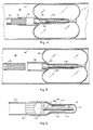
- the detachable balloon catheter apparatus of the present invention consists of a single lumen introducer catheter 102, a valve mechanism generally designated 104, a valve seat 106, a masking sleeve 108 and an inflatable balloon 110.
- Introducer catheter 102 is elongated, has a small diameter and is made of a moderately flexible material, such as an elastomer material containing organosilicon polymers, generally known by the Trademark "Silastic" or polyurethane.
- the flexibility of the material is chosen so that the catheter can be digitally maneuvered or "snaked" through the human blood vessels, particularly the intracranial arteries.
- the introducer catheter is open at both ends with the trailing end having a fitting (not shown) for connection to a conventional source of pressurized fluid, such as a syringe (not shown) containing a saline or radiopaque solution.
- the interior of the introducer catheter 102 is provided with a plurality of fluid channels that are formed by longitudinal ribs 103.
- the fluid channels formed by ribs 103 provide fluid passageways around an enlarged valve head 116 positioned inside the leading end of introducer catheter 102, so that fluid may be injected into the balloon 110 to inflate it, as described in greater detail below.
- the longitudinal ribs 103 may be straight or slightly arcuate.
- the leading end of catheter 102 may have a smooth interior lumen and the enlarged valve head 116 may be provided with grooves or ribs to form the described fluid channels.
- the dimensions of the introducer catheter 102 and the detachable balloon assembly are a matter of design choice depending upon the size of the particular blood vessel or cavity in which it is to be used.
- the apparatus 100 may be used to occlude very small blood vessels, as in the brain, where the largest diameter of the apparatus prior to inflation may be approximately 0.025 inch (0.64 mm).
- the apparatus 100 may be used to occlude larger blood vessels or even cavities, such as found in a kidney, an intestinal tract or the fallopian tubes.
- the valve mechanism 104 includes an elongated stem portion 112 at its leading end.
- the trailing end of the valve mechanism 104 is flared as at 114 and is joined to an enlarged head portion 116.
- Enlarged valve head 116 preferably fits snugly within the leading end of the introducer catheter 102 and may cause a portion of the introducer catheter 102 to be slightly stretched.
- the valve seat 106 has a trailing end that is enlarged and expanded to form a collar 118which frictionally fits over the leading end of the introducer catheter 102 and valve head 116. Because of the interferring fit between enlarged valve head 116, introducer catheter 102, and collar 118, the valve mechanism 104, valve seat 106 and balloon 110 remain attached to the introducer catheter 102 during insertion into a blood vessel until detachment of the balloon is desired, as described in more detail below.
- Collar 118 tapers at 120 and terminates in a tubular, elongated leading end 122 that fits telescopically over the stem 112 of valve mechanism 104.
- the elongated, tubular end 122 is somewhat shorter in length than the valve mechanism 104 so that the forward tip 124 of the stem 112 will extend beyond the leading end 122 of valve seat 106, permitting the forward tip 124 of valve mechanism 104 to be bonded to the interior surface of the balloon 110.
- the diameter of the stem 112 is slightly less than the inside diameter of the elongated leading end 122 of valve seat 106 so that the pressurized fluid injected into the balloon 110 may easily pass therethrough.
- Valve seat 106 is preferably made of a flexible polyurethane material, but may also be made of polyvinyl chloride or other suitable material.
- Valve mechanism 104 is preferably made of a material harder than the valve seat 106, such as a hard urethane or polyvinyl chloride material so that a fluid-tight seal can be formed between the valve mechanism 104 and the valve seat 106.
- the inflatable balloon 110 encloses the stem 112 of valve mechanism 104 and the elongated leading end 122 of valve seat 106.
- the balloon 110 is bonded at its opening 119 to the tapered portion 120 of collar 118.
- the interior surface of balloon 110 is bonded to the forward tip 124 of valve stem 112, for purposes of actuating the valve mechanism 104, as will be hereinafter described in more detail.
- Inflatable balloon 110 is made of a suitable elastomeric material, such as polyurethane, latex rubber, or silicone.
- elastomeric material such as polyurethane, latex rubber, or silicone.
- Polyurethane is presently preferred because of its-high strength, resistance to chemical and biological degradation, low membrane porosity, and its high degree of com- patability with a variety of different fluids that may be used to inflate the balloon.
- the balloon 110 could be preformed and then attached to the valve seat 106 by an adhesive
- the balloon 110 is preferably formed by placing a thin (typically 0.001 inch (0.025 mm) thick) masking sleeve 108 snugly over the leading end 122 of valve seat 106.
- the masking sleeve 108 preferably is stretched so that its forward end 125 will taper, thus completely enclosing the leading end 122 of the valve seat 106 while still leaving the forward tip 124 of valve stem 112 exposed.
- valve mechanism 104 When the valve mechanism 104, collar 118 of valve seat 106 and masking sleeve 108 have been assembled and attached to the leading end of catheter 102, the assembly is then dipped into a solution of polyurethane or other suitable elastomeric material. The assembly is dipped into the solution up to the tapered portion 120 of valve seat 106, slightly beyond termination of the trailing end of masking sleeve 108.
- the masking sleeve 108 is made from tetrafluorethylene-hexafluoropropylene copolymer commonly known by the Trademark "Teflon” or other material which will not bond to the elastomeric dipping solution, the balloon 110 will only be bonded to the assembly at the forward tip 124 of the valve stem 112 and at the tapered portion 120 of valve seat 106 which are not covered by the masking sleeve 108.
- the device of the present invention may be designed so that the size and shape of the resulting balloon can be predetermined and the medical surgeon can choose a balloon which will be properly sized and shaped for the particular vessel or cavity in which it will be used.
- the apparatus 100 of the present invention is introduced into the lumen 128 of a blood vessel 130 by first passing a catheter (not shown) of larger diameter into the vessel 130 at the point of entry (not shown). Introducer catheter 102 is then passed through the larger catheter (not shown) and is "snaked” through the vessel 130 to the point where it is desired to occlude the vessel 130. The larger catheter (not shown) can be removed or retained in position during this procedure.
- a portion of the device such as the valve mechanism 104, could be made of a radiopaque material or a silver particle may be embedded in the valve mechanism 104 to allow for fluoroscopic visualization.
- pressurized fluid is injected through the introducer catheter 102 and into the balloon 110 so that it will begin to inflate.
- perfusate fluids there are a number of different types that may be used.
- radiopaque compounds may be preferred to enable visualization during insertion and placement of the balloon.
- isotonic solutions may be preferred so as to minimize tendencies toward osmotic diffusion across the balloon membrane.
- a solidified filler material such as silicone, which can be made to solidify after the balloon 110 is in position.
- the pressurized fluid will flow through the fluid channels formed by ribs 103 around the enlarged valve head 116.
- the fluid will then flow to the interior of the balloon 110 through a passageway 132 formed in the clearance area between valve stem .112 and the surrounding leading end 122 of valve seat 106, and through a slight clearance space 134 between sleeve 108 and valve stem 112 caused by the fluid pressure.
- the balloon 110 will expand longitudinally, as well as radially outward from the valve stem 112. As shown in Figure 3, the radial expansion is limited by the internal diameter of the blood vessel 130 thereby causing the principal mode of expansion to be longitudinal. Since the forward tip 124 of valve stem 112 is bonded to the interior of the balloon 110, longitudinal expansion of the balloon 110 will exert a force on the valve stem 112 (and accordingly, on the entire valve mechanism 104) which will cause the valve mechanism 104 to move laterally forward.
- valve mechanism 104 When the lateral force exerted on the valve mechanism 104 becomes greater than the coefficient of static friction holding enlarged valve head 116 within the leading end of introducer catheter 102, the valve mechanism 104 will be withdrawn from the introducer catheter 102 into frictional engagement with the tapered portion 120 of valve seat 106. It has been found that when the balloon 110 is inflated to its optimum size, the valve mechanism 104 actually "snaps" into the valve seat 106 as though it were spring-loaded, thereby jamming the tapered portion 114 of the valve mechanism 104 into the tapered portion 120 of valve seat 106, forming a fluid-tight seal.
- valve seat 106 As shown in Figure 4, once the valve mechanism 104 has engaged the valve seat 106 in a fluid-tight seal, any additional injection of fluid into the introducer catheter 102 will force the collar 118 of valve seat 106 to expand, creating a small passageway 107 between the introducer catheter 102 and collar 118. It should be observed that the walls of valve seat 106 are specifically constructed so that they will be thinner or made of softer, more compliant material so that they will be more apt to expand than the walls of introducer catheter 102. Thus, the remaining frictional attachment between the introducer catheter 102 and the collar 118 is reduced once the enlarged head portion 116 of valve mechanism 104 is separated from the introducer catheter 102.
- the fluid pressure acts to separate the collar 118 from the introducer catheter 102 by means of the reduced frictional attachment and by means of the lubricity of the fluid flowing through passageway 107 thus detaching the balloon 110 from the introducer catheter 102 which can then be withdrawn from the vessel 130.
- the apparatus and method of the present invention eliminate the risk of bursting the balloon due to over inflation when attempting to detach the balloon from the introducer catheter.
- the balloon is automatically sealed when it reaches the predetermined amount of inflation necessary to occlude the blood vessel, so that further injection of fluid serves only to detach the balloon rather than further inflating it, as in the prior art type devices.
- the apparatus and method of the present invention alleviates many of the other problems encountered with prior art devices. Unlike most prior art devices, the present invention is not subject to slow leaking of the fluid from the valve assembly causing it to collapse within a few weeks after implantation. There are essentially two reasons for this improvement over the prior art: (1) the mating of the valve mechanism 104 in the valve seat 106 provides a greater surface area of contact than in prior art devices, and (2) the longitudinal expansion forces exerted by the balloon 110 on the valve mechanism 104 tend to continuously urge the valve mechanism 104 into a closed, fluid-tight position in the valve seat 106. Accordingly, the greater the forces placed upon the balloon 110 by the blood vessel 130, the stronger the sealing effect of the valve mechanism 104.
- Another major advantage of the present invention is that only a single lumen introducer catheter is necessary, which is both smaller in diameter and more flexible than a double lumen catheter, thus permitting its use in smaller diameter blood vessels.
- the surgeon may inflate, seal and detach the balloon from the catheter. This operative procedure is thus fast, simple, and safe.
- valve mechanism 136 consists of an enlarged head portion 142 and an elongated stem portion 144.
- the forward tip of the valve stem 144 terminates in a button 146.
- the button 146 may be formed by heating the end of valve stem 144 and then compressing it while it is still heated.
- valve seat 138 is diametrally enlarged in relation to the valve stem 144.
- the diametrally enlarged valve seat 138 permits the size and shape of the balloon to be varied, as hereinafter described in more detail.
- the masking sleeve 140 is snugly fit over the leading end 152 of the valve seat 138 and extends out to the flat button 146 formed at the forward tip of the valve stem 144. Further, it will be noted that the diameter of the flat button 146 corresponds to the diameter of the masking sleeve 140 so as to prevent the dipping solution for the balloon from entering into the space 154 formed between the masking sleeve 140 and valve stem 144.
- the valve mechanism 136, valve seat 138 and masking sleeve 140 are assembled and attached to the leading end of catheter 102, the assembled components are then dipped into a urethane solution so as to form the membrane for the balloon 151.
- the balloon 151 will adhere only to the surface of the flat button 146 provided at the forward tip of the valve stem 144 and the portions of the valve seat 138 that are not covered by the masking sleeve 140.
- valve mechanism 158 has an elongated stem 162 that is bonded at its forward tip 163 to the interior of the balloon 164.
- the trailing end of valve mechanism 158 terminates in an enlarged head portion 160 that is tapered and joined to the valve stem 162.
- the enlarged head portion 160 is diametrially reduced in relation to the inside diameter of connecting tube 156.
- Connecting tube 156 is constructed of a semi-rigid plastic material which is somewhat less elastic than the introducer catheter 102. Introducer catheter 102 is stretched at its leading end so as to frictionally fit over the trailing end of the connecting tube 156.
- connecting tube 156 is permanently bonded to the collar portion 166 of valve seat 168.
- the balloon 164 is pre-formed and is bonded to the valve seat 168 along the tapered portion thereof and at the forward tip 163 of valve stem 162, as previously indicated.
- Fluid injected through the introducer catheter 102 will flow around the enlarged head portion 160 since it is diametrially reduced in relation to the inside diameter of connecting tube 156.
- the fluid will then flow through the elongated leading end 152 of valve seat 168 into the interior of the balloon 164, thus inflating the balloon 164.
- the balloon 164 becomes fully inflated radial expansion will be limited by the walls 130 of the blood vessel causing the expansion to be longitudinal, as with the previously described embodiments.
- the longitudinal expansion will exert a force on the valve stem 162 which is attached at its forward tip 163 to the interior of the balloon 164, pulling the valve mechanism 158 forward until the enlarged head portion 160 is tightly seated in fluid-tight engagement with the tapered portion of the valve seat 168.
- valve mechanism 158 Once the valve mechanism 158 is seated in fluid-tight engagement with the valve seat 168 further injection of fluid will cause the leading end of introducer catheter 102 to expand, forcing the fluid between the connecting tube 156 and leading end of introducer catheter 102.
- the fluid will lubricate the connection between the introducer catheter 102 and connecting tube 156 so that the introducer catheter 102 will pull free of the connecting tube 156 thus detaching the inflated balloon assembly from the introducer catheter, which may then be withdrawn.
Landscapes
- Health & Medical Sciences (AREA)
- Surgery (AREA)
- Life Sciences & Earth Sciences (AREA)
- Heart & Thoracic Surgery (AREA)
- Molecular Biology (AREA)
- Vascular Medicine (AREA)
- Engineering & Computer Science (AREA)
- Biomedical Technology (AREA)
- Reproductive Health (AREA)
- Medical Informatics (AREA)
- Nuclear Medicine, Radiotherapy & Molecular Imaging (AREA)
- Animal Behavior & Ethology (AREA)
- General Health & Medical Sciences (AREA)
- Public Health (AREA)
- Veterinary Medicine (AREA)
- Media Introduction/Drainage Providing Device (AREA)
- Surgical Instruments (AREA)
Claims (9)
Applications Claiming Priority (2)
| Application Number | Priority Date | Filing Date | Title |
|---|---|---|---|
| US06/147,814 US4311146A (en) | 1980-05-08 | 1980-05-08 | Detachable balloon catheter apparatus and method |
| US147814 | 1980-05-08 |
Publications (3)
| Publication Number | Publication Date |
|---|---|
| EP0051636A1 EP0051636A1 (de) | 1982-05-19 |
| EP0051636A4 EP0051636A4 (de) | 1984-08-10 |
| EP0051636B1 true EP0051636B1 (de) | 1987-09-16 |
Family
ID=22523007
Family Applications (1)
| Application Number | Title | Priority Date | Filing Date |
|---|---|---|---|
| EP81901260A Expired EP0051636B1 (de) | 1980-05-08 | 1981-04-24 | Abnehmbarer ballonkatheter und herstellungs- sowie anwendungsverfahren |
Country Status (9)
| Country | Link |
|---|---|
| US (1) | US4311146A (de) |
| EP (1) | EP0051636B1 (de) |
| JP (1) | JPS57500720A (de) |
| AU (1) | AU548205B2 (de) |
| CA (1) | CA1156118A (de) |
| DE (1) | DE3176444D1 (de) |
| ES (1) | ES501993A0 (de) |
| IT (1) | IT1138776B (de) |
| WO (1) | WO1981003120A1 (de) |
Families Citing this family (152)
| Publication number | Priority date | Publication date | Assignee | Title |
|---|---|---|---|---|
| US4364392A (en) * | 1980-12-04 | 1982-12-21 | Wisconsin Alumni Research Foundation | Detachable balloon catheter |
| US4416267A (en) * | 1981-12-10 | 1983-11-22 | Garren Lloyd R | Method and apparatus for treating obesity |
| US4899747A (en) * | 1981-12-10 | 1990-02-13 | Garren Lloyd R | Method and appartus for treating obesity |
| US4441495A (en) * | 1982-08-16 | 1984-04-10 | Becton, Dickinson And Company | Detachable balloon catheter device and method of use |
| DD221354B1 (de) * | 1983-09-12 | 1987-03-18 | Stoesslein | Ventilmechanismus |
| FR2565828A1 (fr) * | 1983-11-10 | 1985-12-20 | Alby Albert | Ballonnet a valve detachable d'un catheter destine a sa mise en place |
| US4686973A (en) * | 1984-10-12 | 1987-08-18 | Dow Corning Corporation | Method of making an intramedullary bone plug and bone plug made thereby |
| US4697584A (en) * | 1984-10-12 | 1987-10-06 | Darrel W. Haynes | Device and method for plugging an intramedullary bone canal |
| US5019075A (en) * | 1984-10-24 | 1991-05-28 | The Beth Israel Hospital | Method and apparatus for angioplasty |
| US5226430A (en) * | 1984-10-24 | 1993-07-13 | The Beth Israel Hospital | Method for angioplasty |
| US4681092A (en) * | 1985-05-21 | 1987-07-21 | Kontron Inc. | Balloon catheter wrapping apparatus |
| US4660560A (en) * | 1985-05-30 | 1987-04-28 | The Beth Israel Hospital Association | Method for treating obstructive prostatism |
| US5527336A (en) * | 1986-12-09 | 1996-06-18 | Boston Scientific Corporation | Flow obstruction treatment method |
| US5312430A (en) * | 1986-12-09 | 1994-05-17 | Rosenbluth Robert F | Balloon dilation catheter |
| US5041090A (en) * | 1988-01-12 | 1991-08-20 | Scheglov Viktor I | Occluding device |
| US6004291A (en) * | 1988-02-29 | 1999-12-21 | Scimed Life Systems, Inc. | Intravascular catheter with distal guide wire lumen and transition |
| US5425711A (en) * | 1988-02-29 | 1995-06-20 | Scimed Life Systems, Inc. | Intravascular catheter with distal guide wire lumen and transition member |
| US6071273A (en) * | 1988-02-29 | 2000-06-06 | Scimed Life Systems, Inc. | Fixed wire dilatation balloon catheter |
| US5002558A (en) * | 1989-08-23 | 1991-03-26 | The Beth Israel Hospital Association | Adjustable urethral catheter and method for treating obstructive prostatism |
| US5360402A (en) * | 1990-01-10 | 1994-11-01 | Rochester Medical Corporation | Hand-actuated retention catheter |
| US6626888B1 (en) | 1990-01-10 | 2003-09-30 | Rochester Medical Corporation | Method of shaping structures with an overcoat layer including female urinary catheter |
| US5670111A (en) * | 1990-01-10 | 1997-09-23 | Rochester Medical Corporation | Method of shaping structures with an overcoat layer including female urinary catheter |
| US5971954A (en) * | 1990-01-10 | 1999-10-26 | Rochester Medical Corporation | Method of making catheter |
| CA2044867C (en) * | 1990-06-25 | 1999-10-12 | James J. Rudnick | Direct vision prostate balloon catheter |
| US5304123A (en) * | 1991-10-24 | 1994-04-19 | Children's Medical Center Corporation | Detachable balloon catheter for endoscopic treatment of vesicoureteral reflux |
| US5524633A (en) * | 1991-11-25 | 1996-06-11 | Advanced Surgical, Inc. | Self-deploying isolation bag |
| US5308327A (en) * | 1991-11-25 | 1994-05-03 | Advanced Surgical Inc. | Self-deployed inflatable retractor |
| US5571087A (en) * | 1992-02-10 | 1996-11-05 | Scimed Life Systems, Inc. | Intravascular catheter with distal tip guide wire lumen |
| US5378236A (en) * | 1992-05-15 | 1995-01-03 | C. R. Bard, Inc. | Balloon dilatation catheter with integral detachable guidewire |
| US5382231A (en) * | 1993-02-02 | 1995-01-17 | Shlain; Leonard M. | Method for transesophageal retraction of the stomach |
| US5814062A (en) * | 1994-12-22 | 1998-09-29 | Target Therapeutics, Inc. | Implant delivery assembly with expandable coupling/decoupling mechanism |
| US5830228A (en) * | 1996-05-29 | 1998-11-03 | Urosurge, Inc. | Methods and systems for deployment of a detachable balloon at a target site in vivo |
| US5730734A (en) * | 1996-11-14 | 1998-03-24 | Scimed Life Systems, Inc. | Catheter systems with interchangeable parts |
| US6106889A (en) * | 1998-06-11 | 2000-08-22 | Biocoat Incorporated | Method of selective coating of articles |
| US6632457B1 (en) * | 1998-08-14 | 2003-10-14 | Incept Llc | Composite hydrogel drug delivery systems |
| US6964669B1 (en) | 2000-04-12 | 2005-11-15 | Ams Research Corporation | Linear delivery system for deployment of a detachable balloon at a target site in vivo |
| US7374532B2 (en) | 2000-04-14 | 2008-05-20 | Attenuex Technologies, Inc. | High vapor pressure attenuation device |
| US10327880B2 (en) | 2000-04-14 | 2019-06-25 | Attenuex Technologies, Inc. | Attenuation device for use in an anatomical structure |
| US7470228B2 (en) * | 2000-04-14 | 2008-12-30 | Attenuex Technologies, Inc. | Method of treating benign hypertrophy of the prostate |
| US6682473B1 (en) | 2000-04-14 | 2004-01-27 | Solace Therapeutics, Inc. | Devices and methods for attenuation of pressure waves in the body |
| US6855154B2 (en) | 2000-08-11 | 2005-02-15 | University Of Louisville Research Foundation, Inc. | Endovascular aneurysm treatment device and method |
| US7033373B2 (en) * | 2000-11-03 | 2006-04-25 | Satiety, Inc. | Method and device for use in minimally invasive placement of space-occupying intragastric devices |
| US7160325B2 (en) | 2001-05-15 | 2007-01-09 | Ams Research Corporation | Implantable medical balloon and valve |
| US6558400B2 (en) | 2001-05-30 | 2003-05-06 | Satiety, Inc. | Obesity treatment tools and methods |
| US7083629B2 (en) * | 2001-05-30 | 2006-08-01 | Satiety, Inc. | Overtube apparatus for insertion into a body |
| US20030004534A1 (en) * | 2001-06-01 | 2003-01-02 | George Stephanie A. | Balloon transporter |
| US7338511B2 (en) * | 2002-05-24 | 2008-03-04 | Boston Scientific-Scimed, Inc. | Solid embolic material with variable expansion |
| US6746460B2 (en) * | 2002-08-07 | 2004-06-08 | Satiety, Inc. | Intra-gastric fastening devices |
| US7214233B2 (en) * | 2002-08-30 | 2007-05-08 | Satiety, Inc. | Methods and devices for maintaining a space occupying device in a relatively fixed location within a stomach |
| US7220237B2 (en) * | 2002-10-23 | 2007-05-22 | Satiety, Inc. | Method and device for use in endoscopic organ procedures |
| US7229428B2 (en) * | 2002-10-23 | 2007-06-12 | Satiety, Inc. | Method and device for use in endoscopic organ procedures |
| US7175638B2 (en) | 2003-04-16 | 2007-02-13 | Satiety, Inc. | Method and devices for modifying the function of a body organ |
| US20090259236A2 (en) | 2003-07-28 | 2009-10-15 | Baronova, Inc. | Gastric retaining devices and methods |
| US9498366B2 (en) | 2003-07-28 | 2016-11-22 | Baronova, Inc. | Devices and methods for pyloric anchoring |
| US9700450B2 (en) | 2003-07-28 | 2017-07-11 | Baronova, Inc. | Devices and methods for gastrointestinal stimulation |
| US7914543B2 (en) | 2003-10-14 | 2011-03-29 | Satiety, Inc. | Single fold device for tissue fixation |
| US7097650B2 (en) * | 2003-10-14 | 2006-08-29 | Satiety, Inc. | System for tissue approximation and fixation |
| US20050107802A1 (en) * | 2003-11-19 | 2005-05-19 | Vanasse Thomas M. | Canal sizer and associated method |
| US20050177104A1 (en) * | 2004-01-22 | 2005-08-11 | Rochester Medical Corporation | Cuff resistant foley catheter |
| EP1715826B1 (de) * | 2004-02-02 | 2013-03-06 | Conceptus, Inc. | Verbesserung des einwachsens von gewebe zur kontrazeption |
| US9713549B2 (en) * | 2004-02-02 | 2017-07-25 | Bayer Healthcare Llc | Contraceptive with permeable and impermeable components |
| US20050177176A1 (en) * | 2004-02-05 | 2005-08-11 | Craig Gerbi | Single-fold system for tissue approximation and fixation |
| US8828025B2 (en) * | 2004-02-13 | 2014-09-09 | Ethicon Endo-Surgery, Inc. | Methods and devices for reducing hollow organ volume |
| AU2005218318A1 (en) * | 2004-02-27 | 2005-09-15 | Ethicon Endo-Surgery, Inc | Methods and devices for reducing hollow organ volume |
| US8252009B2 (en) * | 2004-03-09 | 2012-08-28 | Ethicon Endo-Surgery, Inc. | Devices and methods for placement of partitions within a hollow body organ |
| US9028511B2 (en) * | 2004-03-09 | 2015-05-12 | Ethicon Endo-Surgery, Inc. | Devices and methods for placement of partitions within a hollow body organ |
| US8449560B2 (en) | 2004-03-09 | 2013-05-28 | Satiety, Inc. | Devices and methods for placement of partitions within a hollow body organ |
| US8628547B2 (en) * | 2004-03-09 | 2014-01-14 | Ethicon Endo-Surgery, Inc. | Devices and methods for placement of partitions within a hollow body organ |
| CA2561193A1 (en) | 2004-03-26 | 2005-10-20 | Satiety, Inc. | Systems and methods for treating obesity |
| US20070167682A1 (en) | 2004-04-21 | 2007-07-19 | Acclarent, Inc. | Endoscopic methods and devices for transnasal procedures |
| US10188413B1 (en) | 2004-04-21 | 2019-01-29 | Acclarent, Inc. | Deflectable guide catheters and related methods |
| US9399121B2 (en) | 2004-04-21 | 2016-07-26 | Acclarent, Inc. | Systems and methods for transnasal dilation of passageways in the ear, nose or throat |
| US20190314620A1 (en) | 2004-04-21 | 2019-10-17 | Acclarent, Inc. | Apparatus and methods for dilating and modifying ostia of paranasal sinuses and other intranasal or paranasal structures |
| US8702626B1 (en) | 2004-04-21 | 2014-04-22 | Acclarent, Inc. | Guidewires for performing image guided procedures |
| US8747389B2 (en) | 2004-04-21 | 2014-06-10 | Acclarent, Inc. | Systems for treating disorders of the ear, nose and throat |
| US7654997B2 (en) | 2004-04-21 | 2010-02-02 | Acclarent, Inc. | Devices, systems and methods for diagnosing and treating sinusitus and other disorders of the ears, nose and/or throat |
| US8764729B2 (en) | 2004-04-21 | 2014-07-01 | Acclarent, Inc. | Frontal sinus spacer |
| US20060063973A1 (en) | 2004-04-21 | 2006-03-23 | Acclarent, Inc. | Methods and apparatus for treating disorders of the ear, nose and throat |
| US7803150B2 (en) | 2004-04-21 | 2010-09-28 | Acclarent, Inc. | Devices, systems and methods useable for treating sinusitis |
| US8932276B1 (en) | 2004-04-21 | 2015-01-13 | Acclarent, Inc. | Shapeable guide catheters and related methods |
| JP4934024B2 (ja) * | 2004-05-03 | 2012-05-16 | フルフィリウム, インコーポレイテッド | 胃の容量を制御するための方法およびシステム |
| US7112186B2 (en) * | 2004-05-26 | 2006-09-26 | Shah Tilak M | Gastro-occlusive device |
| US8845676B2 (en) | 2004-09-22 | 2014-09-30 | Micro Therapeutics | Micro-spiral implantation device |
| EP1793744B1 (de) | 2004-09-22 | 2008-12-17 | Dendron GmbH | Medizinisches implantat |
| US20060106288A1 (en) | 2004-11-17 | 2006-05-18 | Roth Alex T | Remote tissue retraction device |
| US8070807B2 (en) | 2004-11-19 | 2011-12-06 | Fulfillium, Inc. | Wireless breach detection |
| US9456915B2 (en) | 2004-11-19 | 2016-10-04 | Fulfilium, Inc. | Methods, devices, and systems for obesity treatment |
| WO2014082044A1 (en) | 2012-11-26 | 2014-05-30 | Spatz Fgia, Inc. | System and methods for internalization of components of an adjustable intragastric balloon |
| US9974680B2 (en) | 2004-12-27 | 2018-05-22 | Spatz Fgia, Inc. | System and methods for internalization of external components of adjustable intragastric balloon |
| US7785291B2 (en) * | 2005-03-01 | 2010-08-31 | Tulip Medical Ltd. | Bioerodible self-deployable intragastric implants |
| US7699863B2 (en) * | 2005-03-01 | 2010-04-20 | Tulip Medical Ltd. | Bioerodible self-deployable intragastric implants |
| US20060222596A1 (en) | 2005-04-01 | 2006-10-05 | Trivascular, Inc. | Non-degradable, low swelling, water soluble radiopaque hydrogel polymer |
| US8864730B2 (en) * | 2005-04-12 | 2014-10-21 | Rochester Medical Corporation | Silicone rubber male external catheter with absorbent and adhesive |
| US8951225B2 (en) | 2005-06-10 | 2015-02-10 | Acclarent, Inc. | Catheters with non-removable guide members useable for treatment of sinusitis |
| WO2007038476A2 (en) | 2005-09-26 | 2007-04-05 | Atteneux Technologies, Inc. | Pressure attenuation device |
| CA2649702C (en) | 2006-04-17 | 2014-12-09 | Microtherapeutics, Inc. | System and method for mechanically positioning intravascular implants |
| US8777979B2 (en) | 2006-04-17 | 2014-07-15 | Covidien Lp | System and method for mechanically positioning intravascular implants |
| US7872068B2 (en) * | 2006-05-30 | 2011-01-18 | Incept Llc | Materials formable in situ within a medical device |
| US7892250B2 (en) * | 2006-11-01 | 2011-02-22 | Ethicon Endo-Surgery, Inc. | Use of biosurgical adhesive on inflatable device for gastric restriction |
| US9381334B2 (en) | 2007-01-16 | 2016-07-05 | Radiadyne Llc | Endorectal balloon with gas release lumen |
| US9707379B2 (en) | 2007-01-16 | 2017-07-18 | Radiadyne Llc | Rectal balloon with locking stopper |
| US20080172080A1 (en) * | 2007-01-16 | 2008-07-17 | Isham John | Minimally invasive rectal balloon apparatus |
| US8500771B2 (en) | 2007-01-16 | 2013-08-06 | Radiadyne, Llc | Rectal balloon apparatus with pressure relieving lumen and sensors |
| US8585676B2 (en) | 2007-02-05 | 2013-11-19 | Polyzen Inc. | Multi-lumen lay-flat tubing, catheter articles comprising same, and method of manufacture thereof |
| KR20100015521A (ko) | 2007-03-13 | 2010-02-12 | 마이크로 테라퓨틱스 인코포레이티드 | 임플란트, 맨드릴, 및 임플란트 형성방법 |
| JP5249249B2 (ja) | 2007-03-13 | 2013-07-31 | コヴィディエン リミテッド パートナーシップ | コイルと耐伸張性部材とが含まれているインプラント |
| WO2008127638A2 (en) * | 2007-04-13 | 2008-10-23 | Biomet Microfixation, Llc | Neurosurgical balloon retractor |
| US8105299B2 (en) * | 2007-04-23 | 2012-01-31 | Polyzen Inc. | Extrusion blow-molded corporeal port mounting structure |
| US8167859B2 (en) * | 2007-04-23 | 2012-05-01 | Polyzen Inc. | Ostomy bag mounting structure |
| US7976497B2 (en) | 2007-09-25 | 2011-07-12 | Polyzen Inc. | Multi-layer film welded articulated balloon |
| CA2705709C (en) | 2007-11-16 | 2016-03-15 | Synthes Usa, Llc | Porous containment device and associated method for stabilization of vertebral compression fractures |
| US20090259210A1 (en) * | 2008-04-10 | 2009-10-15 | Sabbah Hani N | Method, apparatus and kits for forming structural members within the cardiac venous system |
| AU2009293312B2 (en) | 2008-09-18 | 2015-07-09 | Acclarent, Inc. | Methods and apparatus for treating disorders of the ear nose and throat |
| EP2367503A1 (de) | 2008-11-25 | 2011-09-28 | AttenueX Technologies, Inc. | Implantat mit medium mit hohem dampfdruck |
| JP5890182B2 (ja) * | 2009-02-12 | 2016-03-22 | インセプト エルエルシー | ヒドロゲルプラグによる薬物送達 |
| US20100274189A1 (en) * | 2009-04-22 | 2010-10-28 | Pressure Products Medical Supplies Inc. | Balloon catheter and method of manufacture of the same |
| US8608642B2 (en) * | 2010-02-25 | 2013-12-17 | Ethicon Endo-Surgery, Inc. | Methods and devices for treating morbid obesity using hydrogel |
| AU2012207387B2 (en) * | 2011-01-17 | 2017-02-16 | Artio Medical, Inc. | Ballstent device and methods of use |
| US11484318B2 (en) | 2011-01-17 | 2022-11-01 | Artio Medical, Inc. | Expandable body device and method of use |
| US9707375B2 (en) | 2011-03-14 | 2017-07-18 | Rochester Medical Corporation, a subsidiary of C. R. Bard, Inc. | Catheter grip and method |
| US10028745B2 (en) | 2011-03-30 | 2018-07-24 | Noha, Llc | Advanced endovascular clip and method of using same |
| US10398444B2 (en) | 2011-03-30 | 2019-09-03 | Noha, Llc | Advanced endovascular clip and method of using same |
| US8449525B2 (en) * | 2011-06-21 | 2013-05-28 | Covidien Lp | Dialysis catheter assembly |
| US9017366B2 (en) * | 2011-08-19 | 2015-04-28 | Empirilon Technology, Llc | Methods and systems for performing intralumenal procedures |
| US20130046326A1 (en) * | 2011-08-19 | 2013-02-21 | Donald K. Jones | Methods and systems for performing intralumenal procedures |
| US9579104B2 (en) | 2011-11-30 | 2017-02-28 | Covidien Lp | Positioning and detaching implants |
| JP6356612B2 (ja) | 2012-01-17 | 2018-07-11 | メタクティブ・メディカル・インコーポレイテッドMetactive Medical, Inc. | 拡張式本体デバイスおよび使用方法 |
| US9011480B2 (en) | 2012-01-20 | 2015-04-21 | Covidien Lp | Aneurysm treatment coils |
| US9687245B2 (en) | 2012-03-23 | 2017-06-27 | Covidien Lp | Occlusive devices and methods of use |
| TWI469761B (zh) * | 2012-05-23 | 2015-01-21 | Advanced Medical Design Internat Llc | 一種無充氣式球囊懸吊系統 |
| WO2013183058A2 (en) | 2012-06-07 | 2013-12-12 | Tulip Medical Ltd. | Expanded device |
| US20140018836A1 (en) * | 2012-07-13 | 2014-01-16 | Top-Bound Enterprise Co., Ltd | Endo-Safe-Bag-Gasless support system |
| US8894563B2 (en) | 2012-08-10 | 2014-11-25 | Attenuex Technologies, Inc. | Methods and systems for performing a medical procedure |
| US9872969B2 (en) | 2012-11-20 | 2018-01-23 | Rochester Medical Corporation, a subsidiary of C.R. Bard, Inc. | Catheter in bag without additional packaging |
| US10092728B2 (en) | 2012-11-20 | 2018-10-09 | Rochester Medical Corporation, a subsidiary of C.R. Bard, Inc. | Sheath for securing urinary catheter |
| HK1225258B (en) * | 2013-08-08 | 2017-09-08 | Global Bio Therapeutics, Inc. | Clamping device for minimally invasive surgery |
| US9539041B2 (en) | 2013-09-12 | 2017-01-10 | DePuy Synthes Products, Inc. | Minimally invasive biomaterial injection system |
| EP3091962B1 (de) | 2013-12-05 | 2022-06-08 | Epitomee Medical Ltd. | Rückhaltevorrichtungen und systeme zur in-situ-freisetzung von pharmazeutischen wirkstoffen |
| US9713475B2 (en) | 2014-04-18 | 2017-07-25 | Covidien Lp | Embolic medical devices |
| CA2957085C (en) | 2014-08-26 | 2023-01-17 | C.R. Bard, Inc. | Packaging and hydrophilic coating of urinary catheter |
| RU2721288C2 (ru) | 2014-09-17 | 2020-05-18 | Метэктив Медикал, Инк. | Медицинское устройство для лечения мешотчатых аневризм |
| US10322269B1 (en) | 2015-01-19 | 2019-06-18 | Dalent, LLC | Dilator device |
| CN110461408B (zh) | 2017-02-09 | 2022-01-21 | 斯帕茨菲亚有限公司 | 用于胃肠球囊的具有对接站的止回阀 |
| WO2018176064A2 (en) | 2017-03-24 | 2018-09-27 | Metactive Medical, Inc. | Medical devices comprising detachable balloons and methods of manufacturing and use |
| EP3615121A4 (de) * | 2017-04-24 | 2020-12-30 | The General Hospital Corporation | Transnasaler katheter zur bildgebung und biopsierung interner luminaler organe |
| EP3675779B1 (de) | 2017-09-19 | 2025-09-10 | C. R. Bard, Inc. | Vorrichtung zur überbrückung von harnkathetern, systeme und verfahren dafür |
| MX2021007298A (es) | 2018-12-21 | 2021-07-15 | Spatz FGIA Ltd | Valvula con estacion de acoplamiento para globo gastrointestinal. |
| WO2020163625A1 (en) | 2019-02-07 | 2020-08-13 | Solace Therapeutics, Inc. | Pressure attenuation device |
| USD877325S1 (en) | 2019-06-06 | 2020-03-03 | Dalent, LLC | Inflatable therapeutic treatment balloon device |
| EP3982851A4 (de) | 2019-06-11 | 2023-08-16 | Dalent, LLC | Ballondilatationsvorrichtung |
| EP4364777B1 (de) | 2020-08-03 | 2026-05-06 | C. R. Bard, Inc. | Intermittierende katheteranordnungen und verfahren dafür |
| US12611519B2 (en) | 2020-09-11 | 2026-04-28 | C. R. Bard, Inc. | Intermittent-catheter assembly and methods thereof |
Family Cites Families (32)
| Publication number | Priority date | Publication date | Assignee | Title |
|---|---|---|---|---|
| US600967A (en) * | 1898-03-22 | Rebounding toy balloon | ||
| US2043630A (en) * | 1935-11-09 | 1936-06-09 | Davol Rubber Co | Construction of rubber articles |
| US2493326A (en) * | 1949-03-01 | 1950-01-03 | John H Trinder | Tampon for control of intractable nasal hemorrhages |
| GB782496A (en) | 1954-11-29 | 1957-09-11 | Arnold & Sons Veterinary Instr | Apparatus for sterilizing female animals |
| US3030953A (en) * | 1957-10-17 | 1962-04-24 | Wilbur R Koehn | Apparatus for applying catheter |
| US2930377A (en) * | 1958-06-02 | 1960-03-29 | Baxter Don Inc | Surgical tube |
| US3039468A (en) * | 1959-01-07 | 1962-06-19 | Joseph L Price | Trocar and method of treating bloat |
| US3108593A (en) * | 1961-03-13 | 1963-10-29 | Jacob A Glassman | Surgical extractor |
| US3435826A (en) * | 1964-05-27 | 1969-04-01 | Edwards Lab Inc | Embolectomy catheter |
| US3334629A (en) * | 1964-11-09 | 1967-08-08 | Bertram D Cohn | Occlusive device for inferior vena cava |
| US3467101A (en) * | 1965-09-30 | 1969-09-16 | Edwards Lab Inc | Balloon catheter |
| US3448739A (en) * | 1966-08-22 | 1969-06-10 | Edwards Lab Inc | Double lumen diagnostic balloon catheter |
| US3452756A (en) * | 1966-10-10 | 1969-07-01 | American Hospital Supply Corp | Medical catheter with plastic balloon requiring low inflation force and method of making same |
| US3512528A (en) * | 1967-05-29 | 1970-05-19 | Kimberly Clark Co | Expandable tampon |
| US3540431A (en) * | 1968-04-04 | 1970-11-17 | Kazi Mobin Uddin | Collapsible filter for fluid flowing in closed passageway |
| US3544668A (en) * | 1968-07-22 | 1970-12-01 | Davol Inc | Method of manufacturing a balloon catheter |
| US3539674A (en) * | 1968-07-22 | 1970-11-10 | Davol Inc | Method of manufacturing a plastic catheter |
| US3625793A (en) * | 1969-09-23 | 1971-12-07 | David S Sheridan | Balloon-type catheters and method of manufacture |
| US3834394A (en) * | 1969-11-21 | 1974-09-10 | R Sessions | Occlusion device and method and apparatus for inserting the same |
| US3642004A (en) * | 1970-01-05 | 1972-02-15 | Life Support Equipment Corp | Urethral valve |
| GB1380991A (en) * | 1972-02-01 | 1975-01-22 | Searle & Co | Catheters |
| US3850176A (en) * | 1972-02-07 | 1974-11-26 | G Gottschalk | Nasal tampon |
| US3795240A (en) * | 1972-03-29 | 1974-03-05 | Hoffmann La Roche | Respiratory distress stimulator system |
| US3833003A (en) * | 1972-07-05 | 1974-09-03 | A Taricco | Intravascular occluding catheter |
| US3795246A (en) * | 1973-01-26 | 1974-03-05 | Bard Inc C R | Venocclusion device |
| SU542523A1 (ru) | 1973-05-04 | 1977-01-15 | Ленинградский научно-исследовательский нейрохирургический институт им. проф. А.Л.Поленова | Устройство дл операций на сосудах |
| US4029104A (en) * | 1976-03-08 | 1977-06-14 | Kerber Charles W | Calibrated leak balloon micro-catheter |
| US4085757A (en) * | 1976-04-29 | 1978-04-25 | P Pevsner | Miniature balloon catheter method and apparatus |
| US4122869A (en) * | 1976-11-12 | 1978-10-31 | Roberson Walter H Sr | Closure plug assembly |
| US4137906A (en) * | 1977-05-05 | 1979-02-06 | Koken Co., Ltd. | Catheter apparatus with occlusion and flow diverting means |
| US4160448A (en) * | 1977-05-23 | 1979-07-10 | Jackson Richard R | Blood pressure measuring catheter |
| DE2837813C3 (de) * | 1978-08-30 | 1981-08-20 | Willy Rüsch GmbH & Co KG, 7053 Kernen | Verfahren zum Herstellen eines medizinischen Tubus oder Katheters |
-
1980
- 1980-05-08 US US06/147,814 patent/US4311146A/en not_active Expired - Lifetime
-
1981
- 1981-04-24 EP EP81901260A patent/EP0051636B1/de not_active Expired
- 1981-04-24 JP JP56501722A patent/JPS57500720A/ja active Pending
- 1981-04-24 DE DE8181901260T patent/DE3176444D1/de not_active Expired
- 1981-04-24 WO PCT/US1981/000541 patent/WO1981003120A1/en not_active Ceased
- 1981-04-24 AU AU71737/81A patent/AU548205B2/en not_active Ceased
- 1981-04-27 CA CA000376264A patent/CA1156118A/en not_active Expired
- 1981-05-07 ES ES501993A patent/ES501993A0/es active Granted
- 1981-05-08 IT IT21599/81A patent/IT1138776B/it active
Also Published As
| Publication number | Publication date |
|---|---|
| CA1156118A (en) | 1983-11-01 |
| DE3176444D1 (en) | 1987-10-22 |
| AU548205B2 (en) | 1985-11-28 |
| IT1138776B (it) | 1986-09-17 |
| WO1981003120A1 (en) | 1981-11-12 |
| IT8121599A0 (it) | 1981-05-08 |
| AU7173781A (en) | 1981-11-26 |
| EP0051636A1 (de) | 1982-05-19 |
| US4311146A (en) | 1982-01-19 |
| JPS57500720A (de) | 1982-04-30 |
| ES8205563A1 (es) | 1982-07-01 |
| ES501993A0 (es) | 1982-07-01 |
| EP0051636A4 (de) | 1984-08-10 |
Similar Documents
| Publication | Publication Date | Title |
|---|---|---|
| EP0051636B1 (de) | Abnehmbarer ballonkatheter und herstellungs- sowie anwendungsverfahren | |
| US4395806A (en) | Method of manufacturing a detachable balloon catheter assembly | |
| US6379329B1 (en) | Detachable balloon embolization device and method | |
| US4441495A (en) | Detachable balloon catheter device and method of use | |
| US6293960B1 (en) | Catheter with shape memory polymer distal tip for deployment of therapeutic devices | |
| US5181921A (en) | Detachable balloon with two self-sealing valves | |
| JP4429589B2 (ja) | 閉塞部材を用いる動脈瘤塞栓装置 | |
| US4471779A (en) | Miniature balloon catheter | |
| EP0664104B1 (de) | Ballonkatheter zum Verschliessen von Aneurysmen oder Nebenblutgefässen | |
| EP2430982B1 (de) | System zur abdichtung von perkutanen punktionen | |
| US5779672A (en) | Dual valve detachable occlusion balloon and over-the-wire delivery apparatus and method for use therewith | |
| EP1010396B1 (de) | Kathetersystem zum hydraulischen Auslösen von Embolisierungsspiralen | |
| EP1355693B1 (de) | System zum Einführen einer Emboliespirale | |
| US5411509A (en) | Embolectomy catheter | |
| CN110996805A (zh) | 粘合封堵系统 | |
| JP2000506051A (ja) | カニューレおよびその製造と使用方法 | |
| KR20150139479A (ko) | 색전 조성물을 전달하기 위한 장치 및 방법 | |
| JPH04671B2 (de) | ||
| US5868764A (en) | Perfusion and occlusion device and method | |
| EP3253301B1 (de) | Okklusionsvorrichtungen | |
| US20210204925A1 (en) | Balloon closure device | |
| US20020120234A1 (en) | Suction occluder for blood vessels and other body lumens | |
| CA2179074A1 (en) | Intra-vascular indwelling arterial perfusion balloon catheter | |
| JP2600710Y2 (ja) | 管状器官の治療具 | |
| JP2600709Y2 (ja) | 管状器官の治療具 |
Legal Events
| Date | Code | Title | Description |
|---|---|---|---|
| PUAI | Public reference made under article 153(3) epc to a published international application that has entered the european phase |
Free format text: ORIGINAL CODE: 0009012 |
|
| AK | Designated contracting states |
Designated state(s): CH DE FR GB NL SE |
|
| 17P | Request for examination filed |
Effective date: 19820308 |
|
| GRAA | (expected) grant |
Free format text: ORIGINAL CODE: 0009210 |
|
| AK | Designated contracting states |
Kind code of ref document: B1 Designated state(s): CH DE FR GB LI NL SE |
|
| REF | Corresponds to: |
Ref document number: 3176444 Country of ref document: DE Date of ref document: 19871022 |
|
| ET | Fr: translation filed | ||
| PG25 | Lapsed in a contracting state [announced via postgrant information from national office to epo] |
Ref country code: GB Effective date: 19880424 |
|
| PG25 | Lapsed in a contracting state [announced via postgrant information from national office to epo] |
Ref country code: SE Effective date: 19880425 |
|
| PG25 | Lapsed in a contracting state [announced via postgrant information from national office to epo] |
Ref country code: LI Effective date: 19880430 Ref country code: CH Effective date: 19880430 |
|
| PLBE | No opposition filed within time limit |
Free format text: ORIGINAL CODE: 0009261 |
|
| STAA | Information on the status of an ep patent application or granted ep patent |
Free format text: STATUS: NO OPPOSITION FILED WITHIN TIME LIMIT |
|
| 26N | No opposition filed | ||
| PG25 | Lapsed in a contracting state [announced via postgrant information from national office to epo] |
Ref country code: NL Effective date: 19881101 |
|
| NLV4 | Nl: lapsed or anulled due to non-payment of the annual fee | ||
| GBPC | Gb: european patent ceased through non-payment of renewal fee | ||
| PG25 | Lapsed in a contracting state [announced via postgrant information from national office to epo] |
Ref country code: FR Free format text: LAPSE BECAUSE OF NON-PAYMENT OF DUE FEES Effective date: 19881229 |
|
| REG | Reference to a national code |
Ref country code: CH Ref legal event code: PL |
|
| PG25 | Lapsed in a contracting state [announced via postgrant information from national office to epo] |
Ref country code: DE Effective date: 19890103 |
|
| REG | Reference to a national code |
Ref country code: FR Ref legal event code: ST |
|
| EUG | Se: european patent has lapsed |
Ref document number: 81901260.0 Effective date: 19890726 |