EP0051763B1 - Ausrüstung zum Spritzgiessen von Brillenbügeln aus Kunststoff mit Metallkern - Google Patents
Ausrüstung zum Spritzgiessen von Brillenbügeln aus Kunststoff mit Metallkern Download PDFInfo
- Publication number
- EP0051763B1 EP0051763B1 EP81108498A EP81108498A EP0051763B1 EP 0051763 B1 EP0051763 B1 EP 0051763B1 EP 81108498 A EP81108498 A EP 81108498A EP 81108498 A EP81108498 A EP 81108498A EP 0051763 B1 EP0051763 B1 EP 0051763B1
- Authority
- EP
- European Patent Office
- Prior art keywords
- stem
- equipment
- mold
- guide
- hinge
- Prior art date
- Legal status (The legal status is an assumption and is not a legal conclusion. Google has not performed a legal analysis and makes no representation as to the accuracy of the status listed.)
- Expired
Links
- 239000002184 metal Substances 0.000 title claims abstract description 29
- 239000000463 material Substances 0.000 title claims abstract description 12
- 229920003023 plastic Polymers 0.000 title claims abstract description 11
- 239000004033 plastic Substances 0.000 title claims abstract description 11
- 238000001746 injection moulding Methods 0.000 title claims abstract description 8
- 238000005096 rolling process Methods 0.000 claims description 3
- 238000000034 method Methods 0.000 description 7
- 238000000465 moulding Methods 0.000 description 5
- 238000002347 injection Methods 0.000 description 4
- 239000007924 injection Substances 0.000 description 4
- 230000000717 retained effect Effects 0.000 description 2
- 230000001464 adherent effect Effects 0.000 description 1
- 230000002950 deficient Effects 0.000 description 1
- 230000000694 effects Effects 0.000 description 1
- 230000002045 lasting effect Effects 0.000 description 1
- 230000000284 resting effect Effects 0.000 description 1
Images



Classifications
-
- B—PERFORMING OPERATIONS; TRANSPORTING
- B29—WORKING OF PLASTICS; WORKING OF SUBSTANCES IN A PLASTIC STATE IN GENERAL
- B29C—SHAPING OR JOINING OF PLASTICS; SHAPING OF MATERIAL IN A PLASTIC STATE, NOT OTHERWISE PROVIDED FOR; AFTER-TREATMENT OF THE SHAPED PRODUCTS, e.g. REPAIRING
- B29C45/00—Injection moulding, i.e. forcing the required volume of moulding material through a nozzle into a closed mould; Apparatus therefor
- B29C45/14—Injection moulding, i.e. forcing the required volume of moulding material through a nozzle into a closed mould; Apparatus therefor incorporating preformed parts or layers, e.g. injection moulding around inserts or for coating articles
- B29C45/14008—Inserting articles into the mould
-
- B—PERFORMING OPERATIONS; TRANSPORTING
- B29—WORKING OF PLASTICS; WORKING OF SUBSTANCES IN A PLASTIC STATE IN GENERAL
- B29C—SHAPING OR JOINING OF PLASTICS; SHAPING OF MATERIAL IN A PLASTIC STATE, NOT OTHERWISE PROVIDED FOR; AFTER-TREATMENT OF THE SHAPED PRODUCTS, e.g. REPAIRING
- B29C45/00—Injection moulding, i.e. forcing the required volume of moulding material through a nozzle into a closed mould; Apparatus therefor
- B29C45/0053—Injection moulding, i.e. forcing the required volume of moulding material through a nozzle into a closed mould; Apparatus therefor combined with a final operation, e.g. shaping
-
- B—PERFORMING OPERATIONS; TRANSPORTING
- B29—WORKING OF PLASTICS; WORKING OF SUBSTANCES IN A PLASTIC STATE IN GENERAL
- B29D—PRODUCING PARTICULAR ARTICLES FROM PLASTICS OR FROM SUBSTANCES IN A PLASTIC STATE
- B29D12/00—Producing frames
- B29D12/02—Spectacle frames
Definitions
- the present invention relates to an equipment for the injection molding of bars for spectacles, made of plastic material and incorporating a metal stem or core onto which the respective metal hinge is previously welded, or obtained in one piece therewith.
- a first technique (DE-B-1729034), one produces first of all a bar preform by injection molding.
- the preform is heated and a metal core, provided at one end with the respective hinge, is introduced with its other end into the preform, wherein it is caused to slide along the longitudinal axis thereof.
- the preform is heated to the softening point, so as to allow the introduction therein of the pointed and relatively narrow metal core.
- the preform undergoes further treatment so as to acquire the final shape of the spectacle bar.
- this technique involves:
- the metal cores are therefore perfectly rectilinear, with no hinges or other projecting parts.
- the bar At the end of the molding stage and after introduction of the metal core, the bar will be provided with its hinge in a subsequent working stage.
- the hinge is usually fixed by riveting or similar techniques.
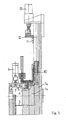
- the molding equipment comprises a mold in two parts 1a and 1b, which are shown closed one against the other in Figure 1, while Figure 2 shows only the mold part 1a, open.
- the mold cavities 2 are molded the bars in their final shape; the plastic material is injected through passages 3.
- the injection ducts and the other parts of the actual molding machine are not shown in detail, as they are of known type.
- the upper part of the mold cavities 2 is closed by a knife element 4.
- This upper part of the cavity corresponds to that designed to form the end of the bar provided with the hinge.
- the knife 4 is mounted on a slide 5, which can be shifted in a direction transversal to the longitudinal axis of the mold cavities 2.
- the movement of the slide 5 is controlled by a cylinder 6 by means of two toggle-joint levers 7 and 8.
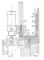
- a guide 10, for the metal stem stiffening the bars, is provided on the extension of the longitudinal axis of the cavities 2, as shown in detail in Figures 3 to 5.
- an operating finger 11 mounted on a slide 12 and movable along said longitudinal axis under the control of the cylinder 13.
- the guide 10 practically consists of an axial groove, formed into a rigid piece 10a, fixedly connected to the casing of the machine.
- the groove 10 is shaped so as to exactly house the stiffening stem 15 or, more precisely, so as to house with no slack all its lateral faces except for one. Since, generally, the stiffening stem 15 has a rectangular or substantially rectangular section, the groove 10 will be shaped so as to provide a proper support for one of the major faces and for the two sides, as for the stem shown in Figure 5 (which has a rectangular section with two ribs on the major faces).
- the stem 15 is perfectly guided on three of its faces; the guiding in correspondence of the fourth face is guaranteed - as clearly shown in Figure 5 - by a plurality of rollers 16, with axis perpendicular to that of the groove 10, housed with a minimum slack and slidable into a track 17 formed between a pair of opposed guiding profiles 18.
- the stem 15 is firmly held in position - though with possibility to slide in the axial direction - by bearing with three of its faces inside the guide 10 and by resting its fourth face against the lateral surface of the rollers 16.
- each of the rollers 16 is in turn provided with an annular groove, the profile of which mates with said rib. This guarantees a more precise and proper bearing on the fourth face.
- section of the stem 15 can also be quite different from that shown in the drawings, for instance it can be triangular. In each case it is anyhow indispensable for the groove of the guide 10 to provide a slackless housing for most of the faces of the stem, while at least the face onto which is welded the hinge part should be retained or supported by the rollers 16.
- This arrangement is conceived for guiding a stem 15 as that illustrated in Figures 3 and 4, namely provided with a hinge 20 which has been previously welded in correspondence of its end 15" opposite to its tip 15'.
- Figure 6 shows a different embodiment in which the track 17, between the profiles 18, is far less wide and is used for guiding a flexible metal. lamina 30.
- the track 17 is connected to the channel 22 and to the container 23 through arched channel sections, as illustrated.
- Figure 8 finally illustrates a still further embodiment in which the fourth face of the stem 15 is retained by a plurality of pawls 31, oscillating about pins 32 perpendicular to the surface of said fourth face.
- Said pawls are normally held - by spring means not shown - in the position represented in Figure 8, in which their end is placed astride of the groove forming the guide 10. In this position, as can easily be understood, they form a closing element for the guide 10 and they firmly retain the stem 15.
- the stem 15 is correctly housed and centered within the plastic material previously injected into the cavity 2, while its hinge part 20 projects therefrom, in the position indicated by 20' with dotted lines.
- the mold can be opened and the bars are withdrawn finished, that is, both in their final shape determined by the mold, and with the stiffening metal stem or core provided with the respective welded hinge part, already perfectly inserted along its longitudinal median axis.
- the invention is not limited to the embodiments shown, which have been given by mere way of example, but that it includes within its scope all those embodiments, within reach of an expert in the field, in which the stem is guided onto at least one side by means apt to be removed as the stem moves down to penetrate into the mold, whiie the other three sides thereof are guided along a fixed guide essentially in the form of a groove.
Landscapes
- Engineering & Computer Science (AREA)
- Mechanical Engineering (AREA)
- Manufacturing & Machinery (AREA)
- Moulds For Moulding Plastics Or The Like (AREA)
- Injection Moulding Of Plastics Or The Like (AREA)
- Eyeglasses (AREA)
Claims (6)
Priority Applications (1)
| Application Number | Priority Date | Filing Date | Title |
|---|---|---|---|
| AT81108498T ATE18648T1 (de) | 1980-11-11 | 1981-10-19 | Ausruestung zum spritzgiessen von brillenbuegeln aus kunststoff mit metallkern. |
Applications Claiming Priority (2)
| Application Number | Priority Date | Filing Date | Title |
|---|---|---|---|
| IT25873/80A IT1133785B (it) | 1980-11-11 | 1980-11-11 | Apparecchiatura per lo stampaggio ad iniezione di stanghette di occhiali in materiale plastico,con incorporata anima metallica munita di cerniera |
| IT2587380 | 1980-11-11 |
Publications (3)
| Publication Number | Publication Date |
|---|---|
| EP0051763A2 EP0051763A2 (de) | 1982-05-19 |
| EP0051763A3 EP0051763A3 (en) | 1983-08-17 |
| EP0051763B1 true EP0051763B1 (de) | 1986-03-19 |
Family
ID=11217991
Family Applications (1)
| Application Number | Title | Priority Date | Filing Date |
|---|---|---|---|
| EP81108498A Expired EP0051763B1 (de) | 1980-11-11 | 1981-10-19 | Ausrüstung zum Spritzgiessen von Brillenbügeln aus Kunststoff mit Metallkern |
Country Status (5)
| Country | Link |
|---|---|
| US (1) | US4373884A (de) |
| EP (1) | EP0051763B1 (de) |
| AT (1) | ATE18648T1 (de) |
| DE (1) | DE3174137D1 (de) |
| IT (1) | IT1133785B (de) |
Families Citing this family (6)
| Publication number | Priority date | Publication date | Assignee | Title |
|---|---|---|---|---|
| CN100546804C (zh) * | 2007-02-16 | 2009-10-07 | 温州市新韩光学有限公司 | 眼镜腿的胶体注入式制作方法及模具设备 |
| ITPN20080091A1 (it) * | 2008-12-15 | 2010-06-16 | Seit Elettronica Srl | "impianto per la produzione di aste per occhiali" |
| CN101850608A (zh) * | 2010-06-23 | 2010-10-06 | 深圳市龙岗区横岗镇高雅眼镜厂 | 眼镜板材的数控加工控制方法 |
| US9067352B2 (en) * | 2013-08-15 | 2015-06-30 | Optimeyes4U, Inc. | System and process for shot-injection molding an eyeglass temple with a wire core |
| CN105834714B (zh) * | 2016-06-07 | 2017-11-21 | 温州创宇智能设备有限公司 | 一种眼镜脚插芯机 |
| CN109317760A (zh) * | 2018-11-21 | 2019-02-12 | 温州创宇智能设备有限公司 | 一种眼镜脚盖胶机 |
Family Cites Families (10)
| Publication number | Priority date | Publication date | Assignee | Title |
|---|---|---|---|---|
| US1152249A (en) * | 1914-06-03 | 1915-08-31 | Albert W Wells | Ophthalmic mounting. |
| US3135993A (en) * | 1959-10-08 | 1964-06-09 | Brunswick Corp | Molding and assembling apparatus and method |
| US3266100A (en) * | 1963-11-18 | 1966-08-16 | Foster Grant Co Inc | Molding apparatus |
| US3387334A (en) * | 1964-06-10 | 1968-06-11 | Foster Grant Co Inc | Molding apparatus |
| DE1729034B1 (de) * | 1967-06-24 | 1971-03-11 | Bernd Schuessler | Vorrichtung zum Einschieben von Metalleinlagen in Brillenbuegel aus thermoplastischem Kunststoff |
| DE1704595A1 (de) * | 1967-11-09 | 1970-05-14 | Dynamit Nobel Ag | Verfahren und Vorrichtung zur Herstellung von Brillenbuegelrohlingen |
| US3531869A (en) * | 1968-05-22 | 1970-10-06 | Ramon D Criss | Insert molded eyeglass frames |
| DE2101245C3 (de) * | 1971-01-13 | 1980-04-17 | Stepper & Ide, 7301 Scharnhausen | Spritzgießform für Brillenbügel |
| FR2374148A1 (fr) * | 1976-12-17 | 1978-07-13 | Essilor International Sa | Procede de fabrication de moules pour le moulage de faces de montures de lunettes |
| US4144010A (en) * | 1977-05-02 | 1979-03-13 | Bucher-Guyer Ag, Maschinenfabrik | Method of and apparatus for injection molding of injection molded parts containing imbedded inserts |
-
1980
- 1980-11-11 IT IT25873/80A patent/IT1133785B/it active
-
1981
- 1981-10-19 DE DE8181108498T patent/DE3174137D1/de not_active Expired
- 1981-10-19 EP EP81108498A patent/EP0051763B1/de not_active Expired
- 1981-10-19 AT AT81108498T patent/ATE18648T1/de not_active IP Right Cessation
- 1981-11-10 US US06/320,293 patent/US4373884A/en not_active Expired - Fee Related
Also Published As
| Publication number | Publication date |
|---|---|
| IT8025873A0 (it) | 1980-11-11 |
| IT1133785B (it) | 1986-07-09 |
| ATE18648T1 (de) | 1986-04-15 |
| US4373884A (en) | 1983-02-15 |
| DE3174137D1 (en) | 1986-04-24 |
| EP0051763A3 (en) | 1983-08-17 |
| EP0051763A2 (de) | 1982-05-19 |
Similar Documents
| Publication | Publication Date | Title |
|---|---|---|
| EP0051763B1 (de) | Ausrüstung zum Spritzgiessen von Brillenbügeln aus Kunststoff mit Metallkern | |
| CA1132322A (en) | Mold for producing moldings from a plastic compound | |
| AU2003263668A1 (en) | Apparatus and method for manufacturing products from a thermoplastic mass | |
| DK0618857T3 (da) | Fremgangsmåde og indretning til sprøjtestøbning af plastbægre | |
| JPH02153725A (ja) | ジッパーの製造方法およびその装置 | |
| GB940652A (en) | Injection moulding machine | |
| IE44526L (en) | Moulding glass or plastic material. | |
| JPS55140537A (en) | Hot runner for injection molding | |
| GB1411340A (en) | Apparatus and method for fabricating brushes or brush components | |
| US4198371A (en) | Method and apparatus for molding holders for disc-like objects | |
| CA2127617A1 (en) | Process for injection molding arcuately-shaped hollow articles | |
| ITTO980510A1 (it) | Unita' di inserimento per inserire linguette di trazione di cursori di chiusure lampo in macchine per stampaggio ad inserti. | |
| US4856980A (en) | Injection molding apparatus for making parts having complex geometric shapes | |
| WO2005030461A3 (en) | Injection molding apparatus and method | |
| FR2380117A1 (fr) | Procede et dispositif pour le moulage par injection de lentilles ou verres | |
| JPH0671703A (ja) | 樹脂成形用金型装置 | |
| KR20230165434A (ko) | 사출성형장치 | |
| US11312052B2 (en) | Process for producing a molded part | |
| DE69729369D1 (de) | Verfahren zum spritzgiessen von compact discs | |
| FR2667818B1 (fr) | Moule d'injection plastique pour la fabrication de lunettes decorees. | |
| JP2001058335A (ja) | プラスチックの成形方法および成形用金型 | |
| JPS5711030A (en) | Positioning method of lead frame in mold | |
| JPS56123845A (en) | Manufacturing method for injection molded product | |
| Dewhurst et al. | Determination of optimum processing conditions for injection moulding | |
| JPS60224514A (ja) | インサ−ト成形金型 |
Legal Events
| Date | Code | Title | Description |
|---|---|---|---|
| PUAI | Public reference made under article 153(3) epc to a published international application that has entered the european phase |
Free format text: ORIGINAL CODE: 0009012 |
|
| AK | Designated contracting states |
Designated state(s): AT CH DE FR GB LI |
|
| PUAL | Search report despatched |
Free format text: ORIGINAL CODE: 0009013 |
|
| AK | Designated contracting states |
Designated state(s): AT CH DE FR GB LI |
|
| RHK1 | Main classification (correction) |
Ipc: B29D 12/02 |
|
| 17P | Request for examination filed |
Effective date: 19840110 |
|
| GRAA | (expected) grant |
Free format text: ORIGINAL CODE: 0009210 |
|
| AK | Designated contracting states |
Kind code of ref document: B1 Designated state(s): AT CH DE FR GB LI |
|
| PG25 | Lapsed in a contracting state [announced via postgrant information from national office to epo] |
Ref country code: LI Effective date: 19860319 Ref country code: FR Free format text: THE PATENT HAS BEEN ANNULLED BY A DECISION OF A NATIONAL AUTHORITY Effective date: 19860319 Ref country code: CH Effective date: 19860319 Ref country code: AT Effective date: 19860319 |
|
| REF | Corresponds to: |
Ref document number: 18648 Country of ref document: AT Date of ref document: 19860415 Kind code of ref document: T |
|
| REF | Corresponds to: |
Ref document number: 3174137 Country of ref document: DE Date of ref document: 19860424 |
|
| REG | Reference to a national code |
Ref country code: CH Ref legal event code: PL |
|
| EN | Fr: translation not filed | ||
| PLBE | No opposition filed within time limit |
Free format text: ORIGINAL CODE: 0009261 |
|
| STAA | Information on the status of an ep patent application or granted ep patent |
Free format text: STATUS: NO OPPOSITION FILED WITHIN TIME LIMIT |
|
| 26N | No opposition filed | ||
| GBPC | Gb: european patent ceased through non-payment of renewal fee | ||
| PG25 | Lapsed in a contracting state [announced via postgrant information from national office to epo] |
Ref country code: GB Effective date: 19881118 |
|
| PGFP | Annual fee paid to national office [announced via postgrant information from national office to epo] |
Ref country code: DE Payment date: 19921006 Year of fee payment: 12 |
|
| PG25 | Lapsed in a contracting state [announced via postgrant information from national office to epo] |
Ref country code: DE Effective date: 19940701 |