EP0052042A2 - Schutz der Wand eines Zentrifugalabscheiders gegen Verschleiss durch die abgeschiedenen Partikel und Vorrichtung zur Durchführung des Verfahrens - Google Patents
Schutz der Wand eines Zentrifugalabscheiders gegen Verschleiss durch die abgeschiedenen Partikel und Vorrichtung zur Durchführung des Verfahrens Download PDFInfo
- Publication number
- EP0052042A2 EP0052042A2 EP81401689A EP81401689A EP0052042A2 EP 0052042 A2 EP0052042 A2 EP 0052042A2 EP 81401689 A EP81401689 A EP 81401689A EP 81401689 A EP81401689 A EP 81401689A EP 0052042 A2 EP0052042 A2 EP 0052042A2
- Authority
- EP
- European Patent Office
- Prior art keywords
- wall
- revolution
- particles
- elements
- centrifuge
- Prior art date
- Legal status (The legal status is an assumption and is not a legal conclusion. Google has not performed a legal analysis and makes no representation as to the accuracy of the status listed.)
- Ceased
Links
Images

Classifications
-
- B—PERFORMING OPERATIONS; TRANSPORTING
- B04—CENTRIFUGAL APPARATUS OR MACHINES FOR CARRYING-OUT PHYSICAL OR CHEMICAL PROCESSES
- B04C—APPARATUS USING FREE VORTEX FLOW, e.g. CYCLONES
- B04C5/00—Apparatus in which the axial direction of the vortex is reversed
- B04C5/08—Vortex chamber constructions
- B04C5/085—Vortex chamber constructions with wear-resisting arrangements
-
- B—PERFORMING OPERATIONS; TRANSPORTING
- B04—CENTRIFUGAL APPARATUS OR MACHINES FOR CARRYING-OUT PHYSICAL OR CHEMICAL PROCESSES
- B04C—APPARATUS USING FREE VORTEX FLOW, e.g. CYCLONES
- B04C5/00—Apparatus in which the axial direction of the vortex is reversed
- B04C5/08—Vortex chamber constructions
- B04C5/103—Bodies or members, e.g. bulkheads, guides, in the vortex chamber
Definitions
- the present invention relates to centrifuges for the separation of particles suspended in a fluid, in particular a gaseous fluid, of the type comprising a hollow body in which the fluid loaded with particles is rotated.
- the present invention applies in particular to cyclone separators used in particular, but not exclusively, in industrial dedusting installations.
- multi-cyclone dust collectors consisting of a battery of several tens of cyclones or cells
- the internal wall of the cyclones is worn by abrasion under the action of the particles of the product which is separated by centrifugation of the gaseous fluid to be treated.
- This wear is more or less rapid depending on the nature of the product to be separated, the speed of the gas to be treated, the resistance and the thickness of the wall of the cyclone body, the conditions of temperature, hygrometry, acidity, etc. ... and it quickly leads to the piercing of the cell wall.
- the dust contained in the smoke from an urban waste incineration oven is very abrasive and it is rare that the lifetime of the cells exceeds 5.0UO hours without experiencing any damage. It is therefore necessary " to make frequent replacements of defective cells, resulting in high costs of labor and spare parts.
- the object of the present invention is to protect against wear, by simple and inexpensive means, the centrifuges of the type described above.
- the device for implementing the method is characterized in that the wall of revolution of the centrifuge which comprises this wall of revolution and means for circulating, with a rotational movement around the axis, a fluid flow in which are in suspension the particles to be separated in order to centrifuge said particles against said wall, is provided on its internal surface with elements in relief having a surface oriented at least partially transversely to the path of the fluid flow.
- the elements in relief are continuous elements extending substantially in the axial direction.
- These raised elements can be integral with the wall and consist of ribs, grooves or other reliefs but they can be formed by added elements, in particular bars, forming a cage and applied tightly to the wall to be protected.
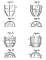
- the cyclone shown in FIGS. 1a and 1b comprises a hollow body 1, for example of cast iron, of cylindro-conical shape and of vertical axis, open at its two ends.
- a discharge tube 2 with an outside diameter smaller than the inside diameter of the body 1 is arranged coaxially in the open upper end of the body 1 and extends downwards inside the latter. over part of its height.
- a ring of fixed guide vanes 3 is fixed to the upper end of the body 1 in the annular space between this body 1 and the tube 2.
- the gas G charged with particles P is admitted at high speed into the body 1 through its upper end, as indicated by the arrows, and it is channeled by the guide vanes 3 which give it a rotational movement around the axis of the body 1. Under the action of centrifugal force, the particles P are projected against the internal wall of the body 1, along which they slide downwards in an approximately helical path to be discharged through the open lower end 4 of the body 1.
- the gas G, freed from the particles P, is evacuated through the tube 2.
- the friction of the particles P on the internal wall of the body 1 wears said wall.
- This wear can be considerably reduced, or even completely eliminated by means of the anti-abrasion device 5 according to the invention which, in the embodiment shown in FIGS. 1a and 1b, consists of bars 6 extending in the axially and bent to the profile of the internal wall of the body 1.
- the bars 6 are kept in close contact with the internal wall of the body 1 by retaining rings 7.
- the number of bars 6 and rings 7 can vary according to the diameter inside and the axial length of the body 1 and according to the operating conditions.
- abrasion-resistant device 5 in accordance with that shown in FIGS. 1a and 1b. Each cell had an internal diameter of approximately 250 mm.
- Each abrasion-resistant device 5 consisted of four vertical bars 6 spaced circumferentially by 90 ° and by two retaining rings 7: The four bars 6 and the two retaining rings were made of 10 mm round iron. in diameter and their total developed length was about 4,000 mm. The test covered 15,000 hours or three years of operation of the furnace at its nominal power.
- the anti-abrasion device 5 makes it possible to considerably increase the life of the cyclones. Tests carried out to date show that the lifespan is at least fivefold.
- the abrasion-resistant device 5 of the invention is of very simple and inexpensive construction insofar as its manufacture requires only a small number of very simple operations and the use of a metal without characteristics. special mechanicals, in common use and inexpensive.
- the only precaution to take for its installation in the body 1 of the cyclone is to take care that the bars 6 are in close contact with the wall to be protected.
- the anti-abrasion device 5 of the invention makes it possible to considerably increase the life of the cyclones, it also makes it possible to maintain the performance predicted by the manufacturers over time, or even to increase the dust removal efficiency. . Indeed; owing to the fact that the protective layer C slightly decreases the cross section of the gases loaded with particles, the speed of these gases is thereby accelerated and the centrifugation is increased. As a result, the separation of the particles is improved and the adhesion of the protective layer C to the wall is greater, which further improves the protection against wear.
- the abrasion-resistant device of the invention can be installed in any type of cyclone with axial or tangential entry, of type vertical, horizontal or oblique, etc. without any modification of the existing facilities.
- the cells which were hitherto manufactured in noble and thick cast irons can now be produced in ordinary and thin cast iron or even in ordinary thin sheets or in stainless steel according to the envisaged applications (temperature, hygrometry, acidity, etc ).
- FIGS 2a and 2b show an embodiment of the cyclone, in which the body 1 is made of sheet metal.
- each bar 6 can be constituted by a sheet folded in L and fixed by one of its wings to the internal wall of the body 1 by any suitable means, for example by spot welding.
- any suitable means for example by spot welding.
- a sheet bent in L one can also use iron sections with L, I or C section.
- Figures 3a and 3b show another embodiment of the cyclone according to the invention, in which the body 1 is made of cast iron and has on its internal wall eight longitudinal ribs (only five of them are visible in Figures 3a and 3b) which are spaced circumferentially by 45 ° and are integrally formed with the body 1 by molding.
- the ribs 8 play the same role as the bars 6 of the previous embodiments.
- Figures 4a and 4b show another embodiment of a cyclone, in which the body 1 is also made of cast iron.
- the body 1 has on its internal wall six longitudinal ribs 8 spaced 60 ° apart and molded with the body 1, as well as other ribs 9, also molded with the body 1, which extend in the circumferential direction and are spaced axially so as to form with the ribs 8 a cellular grid.
- Figures 5a and 5b show another embodiment of the invention in which the body 1 is also made of cast iron and has in its inner wall longitudinal grooves 10 coming from molding.
- the longitudinal edges 11 between the adjacent grooves play the same role as the bars 6 or the ribs 8 of the previous embodiments.
- the present invention is applicable in a large number of industries such as: metallurgy, steel industry, glassware, food industries, wood industry, plastics industry, chemical industry, roads, coating and purification stations, sand pits, balastines, thermal power stations, etc.
- pneumatic transport which uses cyclones, becomes possible in the most diverse industries for a large number of reputable abrasive products, such as: dust, soot, dried sludge, ores, sands, gravel, gravel, pebbles, flours, powders, granules, cereal grains, coals, mints, fines, peanuts, nuts, shells, sawdust, shavings, deburring and all products liable to be cycloned.
- abrasive products such as: dust, soot, dried sludge, ores, sands, gravel, gravel, pebbles, flours, powders, granules, cereal grains, coals, mints, fines, peanuts, nuts, shells, sawdust, shavings, deburring and all products liable to be cycloned.
- the present invention is of great economic interest, both by the possibility it gives of protecting existing cyclones with the resulting savings in spare parts and labor, only by the possibility of constructing future cyclones at a lower cost price, through the best results that it provides in terms of particle separation, by reducing atmospheric pollution by discharges into the atmosphere in dust removal techniques, by the energy savings it allows, and by its many fields of application.
Landscapes
- Cyclones (AREA)
- Centrifugal Separators (AREA)
Applications Claiming Priority (2)
| Application Number | Priority Date | Filing Date | Title |
|---|---|---|---|
| FR8023691A FR2493186B1 (fr) | 1980-11-06 | 1980-11-06 | Centrifugeur avec dispositif anti-abrasion, pour la separation de particules en suspension dans un fluide gazeux |
| FR8023691 | 1980-11-06 |
Publications (2)
| Publication Number | Publication Date |
|---|---|
| EP0052042A2 true EP0052042A2 (de) | 1982-05-19 |
| EP0052042A3 EP0052042A3 (de) | 1983-01-05 |
Family
ID=9247729
Family Applications (1)
| Application Number | Title | Priority Date | Filing Date |
|---|---|---|---|
| EP81401689A Ceased EP0052042A3 (de) | 1980-11-06 | 1981-10-23 | Schutz der Wand eines Zentrifugalabscheiders gegen Verschleiss durch die abgeschiedenen Partikel und Vorrichtung zur Durchführung des Verfahrens |
Country Status (3)
| Country | Link |
|---|---|
| EP (1) | EP0052042A3 (de) |
| JP (1) | JPS57107253A (de) |
| FR (1) | FR2493186B1 (de) |
Cited By (7)
| Publication number | Priority date | Publication date | Assignee | Title |
|---|---|---|---|---|
| EP0763384A1 (de) * | 1995-09-15 | 1997-03-19 | GEC ALSTHOM Stein Industrie | Zentrifugalabschneider, insbesondere für einen Kessel mit zirkulierendem Wirbelbett |
| RU2224599C1 (ru) * | 2002-01-29 | 2004-02-27 | Сергей Николаевич Кущенко | Корпус циклона и способ изготовления корпуса циклона |
| WO2004009244A3 (en) * | 2002-07-19 | 2004-06-10 | Shell Oil Co | Cyclone separator with a vortex extender pin |
| RU2234985C1 (ru) * | 2002-03-22 | 2004-08-27 | Сергей Николаевич Кущенко | Корпус циклона и способ изготовления корпуса циклона |
| US7648544B2 (en) | 2002-07-19 | 2010-01-19 | Shell Oil Company | Swirl tube separator |
| US8287613B2 (en) | 2007-06-01 | 2012-10-16 | Shell Oil Company | Gas-solids separator |
| WO2013042084A3 (en) * | 2011-09-22 | 2013-05-30 | Cydaf Technologies Limited | Apparatus for separation and processing of materials |
Families Citing this family (2)
| Publication number | Priority date | Publication date | Assignee | Title |
|---|---|---|---|---|
| JPS57190655A (en) * | 1981-05-20 | 1982-11-24 | Babcock Hitachi Kk | Coal crusher |
| WO2013012003A1 (ja) * | 2011-07-19 | 2013-01-24 | 株式会社コガネイ | フィルタ |
Family Cites Families (4)
| Publication number | Priority date | Publication date | Assignee | Title |
|---|---|---|---|---|
| BE420877A (de) * | 1936-03-11 | |||
| FR1507938A (fr) * | 1967-01-19 | 1967-12-29 | Beloit Corp | Procédé et dispositif pour la séparation centrifuge de particules dans un mélange fluide |
| US3902601A (en) * | 1974-03-14 | 1975-09-02 | Townley Ind Plastics Inc | One piece cyclone cone |
| US4153558A (en) * | 1978-03-08 | 1979-05-08 | Ab Celleco | Hydrocyclone separator |
-
1980
- 1980-11-06 FR FR8023691A patent/FR2493186B1/fr not_active Expired
-
1981
- 1981-10-23 EP EP81401689A patent/EP0052042A3/de not_active Ceased
- 1981-11-02 JP JP17468981A patent/JPS57107253A/ja active Pending
Cited By (9)
| Publication number | Priority date | Publication date | Assignee | Title |
|---|---|---|---|---|
| EP0763384A1 (de) * | 1995-09-15 | 1997-03-19 | GEC ALSTHOM Stein Industrie | Zentrifugalabschneider, insbesondere für einen Kessel mit zirkulierendem Wirbelbett |
| RU2224599C1 (ru) * | 2002-01-29 | 2004-02-27 | Сергей Николаевич Кущенко | Корпус циклона и способ изготовления корпуса циклона |
| RU2234985C1 (ru) * | 2002-03-22 | 2004-08-27 | Сергей Николаевич Кущенко | Корпус циклона и способ изготовления корпуса циклона |
| WO2004009244A3 (en) * | 2002-07-19 | 2004-06-10 | Shell Oil Co | Cyclone separator with a vortex extender pin |
| CN100415381C (zh) * | 2002-07-19 | 2008-09-03 | 国际壳牌研究有限公司 | 涡流管分离器、多级分离器以及分离固体和气体以获得气态流的方法 |
| US7648544B2 (en) | 2002-07-19 | 2010-01-19 | Shell Oil Company | Swirl tube separator |
| US8287613B2 (en) | 2007-06-01 | 2012-10-16 | Shell Oil Company | Gas-solids separator |
| WO2013042084A3 (en) * | 2011-09-22 | 2013-05-30 | Cydaf Technologies Limited | Apparatus for separation and processing of materials |
| US9370753B2 (en) | 2011-09-22 | 2016-06-21 | Cydaf Technologies Limited | Apparatus for separation and processing of materials |
Also Published As
| Publication number | Publication date |
|---|---|
| FR2493186A1 (fr) | 1982-05-07 |
| JPS57107253A (en) | 1982-07-03 |
| FR2493186B1 (fr) | 1985-07-12 |
| EP0052042A3 (de) | 1983-01-05 |
Similar Documents
| Publication | Publication Date | Title |
|---|---|---|
| EP0476496B1 (de) | Verfahren zur Herstellung eines bimetallischen Gussstückes und Verschleissteil nach diesem Verfahren | |
| EP1846721B1 (de) | Glasschmelzofen | |
| CA2984710C (fr) | Four de craquage | |
| FR2493186A1 (fr) | Centrifugeur avec dispositif anti-abrasion, pour la separation de particules en suspension dans un fluide gazeux | |
| EP2740905B1 (de) | Splitter einer axialen turbomaschine, zugehoriger verdichter und axiale turbomaschine | |
| EP2776540A1 (de) | Reaktor zur trocknung und torrefizierung einer biomasse, vorzugsweise einer lignocellulose- biomasse | |
| EP0396463B1 (de) | Starkfeld-Magnetscheider | |
| FR2610217A1 (fr) | Concasseur rotatif a aubes de projection autoprotegees | |
| CN1650041A (zh) | 回转件、叶轮以及具有叶轮的流体机械的抗磨损表面处理方法 | |
| EP0165224B1 (de) | Vorrichtung zur direkten Beheizung | |
| CN102861677A (zh) | 高强度耐磨耐蚀的螺旋卸料沉降离心机及其制造工艺 | |
| FR2668774A1 (fr) | Procede et dispositif de production d'un combustible solide a partir de dechets combustibles. | |
| FR2489169A1 (fr) | Dispositif en vue de separer ou d'enrichir des melanges gazeux | |
| FR3060050A1 (fr) | Roue a aubes comprenant des moyens d'amortissement et un procede de revetement d'une roue a aubes | |
| FR2790545A1 (fr) | Dispositif pour l'extraction de chaleur a partir d'un gaz et four equipe du dispositif | |
| FR2482874A1 (fr) | Brides de fixation de fermeture d'extremite de bol de centrifugeur | |
| EP3885651B1 (de) | Rotierendes ascherostsystem für brennkammer einer verbrennungs- oder vergasungsanlage | |
| FR2790544A1 (fr) | Dispositif pour l'extraction de chaleur a partir de gaz et four equipe du dispositif | |
| CN100564201C (zh) | 输送皮带机用行星式组合滚筒 | |
| EP0623374B1 (de) | Zentrifugalabscheider für Fluide | |
| EP4028692B1 (de) | Verfahren und ofen zum verbrennen von organischen stoffen aus der behandlung von industriellen oder landwirtschaftlichen abfällen oder abwasser, wie schlamm | |
| BE899562A (fr) | Procede et equipement de chauffe directe. | |
| EP1241682B1 (de) | Kernkratwerkkühlmittelpumpe | |
| BE485255A (de) | ||
| CH716145A2 (fr) | Procédé et dispositif de traitement thermique de déchets urbains. |
Legal Events
| Date | Code | Title | Description |
|---|---|---|---|
| PUAI | Public reference made under article 153(3) epc to a published international application that has entered the european phase |
Free format text: ORIGINAL CODE: 0009012 |
|
| AK | Designated contracting states |
Designated state(s): AT BE CH DE GB IT LU NL SE |
|
| PUAL | Search report despatched |
Free format text: ORIGINAL CODE: 0009013 |
|
| AK | Designated contracting states |
Designated state(s): AT BE CH DE GB IT LI LU NL SE |
|
| 17P | Request for examination filed |
Effective date: 19830630 |
|
| STAA | Information on the status of an ep patent application or granted ep patent |
Free format text: STATUS: THE APPLICATION HAS BEEN REFUSED |
|
| 18R | Application refused |
Effective date: 19850223 |