EP0052042A2 - Protection of the wall of a centrifugal separator against abrasion by particles separated by centrifugation, and device for carrying out the method - Google Patents
Protection of the wall of a centrifugal separator against abrasion by particles separated by centrifugation, and device for carrying out the method Download PDFInfo
- Publication number
- EP0052042A2 EP0052042A2 EP81401689A EP81401689A EP0052042A2 EP 0052042 A2 EP0052042 A2 EP 0052042A2 EP 81401689 A EP81401689 A EP 81401689A EP 81401689 A EP81401689 A EP 81401689A EP 0052042 A2 EP0052042 A2 EP 0052042A2
- Authority
- EP
- European Patent Office
- Prior art keywords
- wall
- revolution
- particles
- elements
- centrifuge
- Prior art date
- Legal status (The legal status is an assumption and is not a legal conclusion. Google has not performed a legal analysis and makes no representation as to the accuracy of the status listed.)
- Ceased
Links
Images

Classifications
-
- B—PERFORMING OPERATIONS; TRANSPORTING
- B04—CENTRIFUGAL APPARATUS OR MACHINES FOR CARRYING-OUT PHYSICAL OR CHEMICAL PROCESSES
- B04C—APPARATUS USING FREE VORTEX FLOW, e.g. CYCLONES
- B04C5/00—Apparatus in which the axial direction of the vortex is reversed
- B04C5/08—Vortex chamber constructions
- B04C5/085—Vortex chamber constructions with wear-resisting arrangements
-
- B—PERFORMING OPERATIONS; TRANSPORTING
- B04—CENTRIFUGAL APPARATUS OR MACHINES FOR CARRYING-OUT PHYSICAL OR CHEMICAL PROCESSES
- B04C—APPARATUS USING FREE VORTEX FLOW, e.g. CYCLONES
- B04C5/00—Apparatus in which the axial direction of the vortex is reversed
- B04C5/08—Vortex chamber constructions
- B04C5/103—Bodies or members, e.g. bulkheads, guides, in the vortex chamber
Definitions
- the present invention relates to centrifuges for the separation of particles suspended in a fluid, in particular a gaseous fluid, of the type comprising a hollow body in which the fluid loaded with particles is rotated.
- the present invention applies in particular to cyclone separators used in particular, but not exclusively, in industrial dedusting installations.
- multi-cyclone dust collectors consisting of a battery of several tens of cyclones or cells
- the internal wall of the cyclones is worn by abrasion under the action of the particles of the product which is separated by centrifugation of the gaseous fluid to be treated.
- This wear is more or less rapid depending on the nature of the product to be separated, the speed of the gas to be treated, the resistance and the thickness of the wall of the cyclone body, the conditions of temperature, hygrometry, acidity, etc. ... and it quickly leads to the piercing of the cell wall.
- the dust contained in the smoke from an urban waste incineration oven is very abrasive and it is rare that the lifetime of the cells exceeds 5.0UO hours without experiencing any damage. It is therefore necessary " to make frequent replacements of defective cells, resulting in high costs of labor and spare parts.
- the object of the present invention is to protect against wear, by simple and inexpensive means, the centrifuges of the type described above.
- the device for implementing the method is characterized in that the wall of revolution of the centrifuge which comprises this wall of revolution and means for circulating, with a rotational movement around the axis, a fluid flow in which are in suspension the particles to be separated in order to centrifuge said particles against said wall, is provided on its internal surface with elements in relief having a surface oriented at least partially transversely to the path of the fluid flow.
- the elements in relief are continuous elements extending substantially in the axial direction.
- These raised elements can be integral with the wall and consist of ribs, grooves or other reliefs but they can be formed by added elements, in particular bars, forming a cage and applied tightly to the wall to be protected.
- the cyclone shown in FIGS. 1a and 1b comprises a hollow body 1, for example of cast iron, of cylindro-conical shape and of vertical axis, open at its two ends.
- a discharge tube 2 with an outside diameter smaller than the inside diameter of the body 1 is arranged coaxially in the open upper end of the body 1 and extends downwards inside the latter. over part of its height.
- a ring of fixed guide vanes 3 is fixed to the upper end of the body 1 in the annular space between this body 1 and the tube 2.
- the gas G charged with particles P is admitted at high speed into the body 1 through its upper end, as indicated by the arrows, and it is channeled by the guide vanes 3 which give it a rotational movement around the axis of the body 1. Under the action of centrifugal force, the particles P are projected against the internal wall of the body 1, along which they slide downwards in an approximately helical path to be discharged through the open lower end 4 of the body 1.
- the gas G, freed from the particles P, is evacuated through the tube 2.
- the friction of the particles P on the internal wall of the body 1 wears said wall.
- This wear can be considerably reduced, or even completely eliminated by means of the anti-abrasion device 5 according to the invention which, in the embodiment shown in FIGS. 1a and 1b, consists of bars 6 extending in the axially and bent to the profile of the internal wall of the body 1.
- the bars 6 are kept in close contact with the internal wall of the body 1 by retaining rings 7.
- the number of bars 6 and rings 7 can vary according to the diameter inside and the axial length of the body 1 and according to the operating conditions.
- abrasion-resistant device 5 in accordance with that shown in FIGS. 1a and 1b. Each cell had an internal diameter of approximately 250 mm.
- Each abrasion-resistant device 5 consisted of four vertical bars 6 spaced circumferentially by 90 ° and by two retaining rings 7: The four bars 6 and the two retaining rings were made of 10 mm round iron. in diameter and their total developed length was about 4,000 mm. The test covered 15,000 hours or three years of operation of the furnace at its nominal power.
- the anti-abrasion device 5 makes it possible to considerably increase the life of the cyclones. Tests carried out to date show that the lifespan is at least fivefold.
- the abrasion-resistant device 5 of the invention is of very simple and inexpensive construction insofar as its manufacture requires only a small number of very simple operations and the use of a metal without characteristics. special mechanicals, in common use and inexpensive.
- the only precaution to take for its installation in the body 1 of the cyclone is to take care that the bars 6 are in close contact with the wall to be protected.
- the anti-abrasion device 5 of the invention makes it possible to considerably increase the life of the cyclones, it also makes it possible to maintain the performance predicted by the manufacturers over time, or even to increase the dust removal efficiency. . Indeed; owing to the fact that the protective layer C slightly decreases the cross section of the gases loaded with particles, the speed of these gases is thereby accelerated and the centrifugation is increased. As a result, the separation of the particles is improved and the adhesion of the protective layer C to the wall is greater, which further improves the protection against wear.
- the abrasion-resistant device of the invention can be installed in any type of cyclone with axial or tangential entry, of type vertical, horizontal or oblique, etc. without any modification of the existing facilities.
- the cells which were hitherto manufactured in noble and thick cast irons can now be produced in ordinary and thin cast iron or even in ordinary thin sheets or in stainless steel according to the envisaged applications (temperature, hygrometry, acidity, etc ).
- FIGS 2a and 2b show an embodiment of the cyclone, in which the body 1 is made of sheet metal.
- each bar 6 can be constituted by a sheet folded in L and fixed by one of its wings to the internal wall of the body 1 by any suitable means, for example by spot welding.
- any suitable means for example by spot welding.
- a sheet bent in L one can also use iron sections with L, I or C section.
- Figures 3a and 3b show another embodiment of the cyclone according to the invention, in which the body 1 is made of cast iron and has on its internal wall eight longitudinal ribs (only five of them are visible in Figures 3a and 3b) which are spaced circumferentially by 45 ° and are integrally formed with the body 1 by molding.
- the ribs 8 play the same role as the bars 6 of the previous embodiments.
- Figures 4a and 4b show another embodiment of a cyclone, in which the body 1 is also made of cast iron.
- the body 1 has on its internal wall six longitudinal ribs 8 spaced 60 ° apart and molded with the body 1, as well as other ribs 9, also molded with the body 1, which extend in the circumferential direction and are spaced axially so as to form with the ribs 8 a cellular grid.
- Figures 5a and 5b show another embodiment of the invention in which the body 1 is also made of cast iron and has in its inner wall longitudinal grooves 10 coming from molding.
- the longitudinal edges 11 between the adjacent grooves play the same role as the bars 6 or the ribs 8 of the previous embodiments.
- the present invention is applicable in a large number of industries such as: metallurgy, steel industry, glassware, food industries, wood industry, plastics industry, chemical industry, roads, coating and purification stations, sand pits, balastines, thermal power stations, etc.
- pneumatic transport which uses cyclones, becomes possible in the most diverse industries for a large number of reputable abrasive products, such as: dust, soot, dried sludge, ores, sands, gravel, gravel, pebbles, flours, powders, granules, cereal grains, coals, mints, fines, peanuts, nuts, shells, sawdust, shavings, deburring and all products liable to be cycloned.
- abrasive products such as: dust, soot, dried sludge, ores, sands, gravel, gravel, pebbles, flours, powders, granules, cereal grains, coals, mints, fines, peanuts, nuts, shells, sawdust, shavings, deburring and all products liable to be cycloned.
- the present invention is of great economic interest, both by the possibility it gives of protecting existing cyclones with the resulting savings in spare parts and labor, only by the possibility of constructing future cyclones at a lower cost price, through the best results that it provides in terms of particle separation, by reducing atmospheric pollution by discharges into the atmosphere in dust removal techniques, by the energy savings it allows, and by its many fields of application.
Landscapes
- Cyclones (AREA)
- Centrifugal Separators (AREA)
Abstract
Description
La présente invention concerne les centrifugeurs pour la séparation de particules en suspension dans un fluide, notamment un fluide gazeux, du type comprenant un corps creux dans lequel le fluide chargé de particules est mis en rotation.The present invention relates to centrifuges for the separation of particles suspended in a fluid, in particular a gaseous fluid, of the type comprising a hollow body in which the fluid loaded with particles is rotated.
La présente invention s'applique en particulier aux séparateurs-cyclones utilisés notamment, mais non exclusivement, dans des installations de dépoussiérage industriel. Dans les dépoussiéreurs multicyclones, constitués par une batterie de plusieurs dizaines de cyclones ou cellules, on constate que la paroi interne des cyclones s'use par abrasion sous l'action des particules du produit qui est séparé par centrifugation du fluide gazeux à traiter. Cette usure est plus ou moins rapide selon la nature du produit à séparer, la vitesse du gaz à traiter, la résistance et l'épaisseur de la paroi du corps du cyclone, les conditions de température, d'hygrométrie, d'acidité, etc... et elle aboutit rapidement au percement de la paroi des cellules. Dès qu'une cellule est percée, le rendement du dépoussiéreur décroît et le fonctionnement est perturbé. Il est alors nécessaire de remplacer la cellule défectueuse dans les plus brefs délais pour deux raisons, d'une part afin de respecter les tolérances de la réglementation antipollution et, d'autre part, afin d'éviter que les fuites de suie ou de poussière n'entraînent d'autres dégâts sur les cellules ou les autres éléments voisins. A titre d'exemple, dans un dépoussiéreur multicyclone classique, comprenant 60 cellules qui traitent, avant rejet à l'atmosphère, les fumées d'un four d'incinération de déchets urbains ayant une capacité nominale de traitement de 1500 kg de déchets par heure, il est fréquent d'apercevoir les premiers percements des cellules en fontes les plus résistantes connues sur le marché après 2.000 à 3.000 heures de fonctionnement, avec une baisse corrélative de rendement importante. En effet, les poussières contenues dans les fumées d'un four d'incinération de déchets urbains sont très abrasives et il est rare que la durée de vie des cellules dépasse 5.0UO heures sans connaître aucune avarie. Il est donc nécessaire"de procéder à des remplacements fréquents des cellules défectueuses, ce qui entraîne des coûts élevés de main-d'oeuvre et de pièces de rechange.The present invention applies in particular to cyclone separators used in particular, but not exclusively, in industrial dedusting installations. In multi-cyclone dust collectors, consisting of a battery of several tens of cyclones or cells, it is found that the internal wall of the cyclones is worn by abrasion under the action of the particles of the product which is separated by centrifugation of the gaseous fluid to be treated. This wear is more or less rapid depending on the nature of the product to be separated, the speed of the gas to be treated, the resistance and the thickness of the wall of the cyclone body, the conditions of temperature, hygrometry, acidity, etc. ... and it quickly leads to the piercing of the cell wall. As soon as a cell is pierced, the efficiency of the dust collector decreases and the operation is disturbed. It is then necessary to replace the defective cell as soon as possible for two reasons, firstly in order to respect the tolerances of the antipollution regulations and, on the other hand, in order to avoid that the leaks of soot or dust do not cause other damage on the cells or the other neighboring elements. For example, in a conventional multicyclone dust collector, comprising 60 cells which treat, before discharge into the atmosphere, the fumes from an urban waste incineration furnace with a nominal treatment capacity of 1500 kg of waste per hour , it is common to see the first breakthroughs of the most resistant cast-iron cells known on the market after 2,000 to 3,000 hours of operation, with a correlative drop in significant yield. In fact, the dust contained in the smoke from an urban waste incineration oven is very abrasive and it is rare that the lifetime of the cells exceeds 5.0UO hours without experiencing any damage. It is therefore necessary " to make frequent replacements of defective cells, resulting in high costs of labor and spare parts.
De nombreuses tentatives ont été faites par les constructeurs de cyclones pour rechercher un matériau susceptible de résister plus longtemps à l'usure. Dans la technique de dépoussiérage des fumées, des fontes de diverses duretés et épaisseurs ont été testées. Certains constructeurs emploient des céramiques ou du verre "Pyrex" pour réaliser la paroi des cellules. D'autres constructeurs garnissent d'un matériau dur la paroi interne des cellules. Ces solutions sont souvent onéreuses et ne permettent pas toujours d'obtenir une augmentation notable de la durée de vie des cellules.Many attempts have been made by cyclone manufacturers to find a material capable of withstanding wear for longer. In the smoke dedusting technique, cast irons of various hardnesses and thicknesses have been tested. Some manufacturers use ceramics or "Pyrex" glass to make the cell wall. Other manufacturers fill the inner wall of the cells with hard material. These solutions are often expensive and do not always allow a significant increase in the life of the cells to be obtained.
La présente invention a pour but de protéger contre l'usure, par des moyens simples et peu coûteux, les centrifugeurs du type ci-dessus décrit.The object of the present invention is to protect against wear, by simple and inexpensive means, the centrifuges of the type described above.
Ce but est atteint avec le procédé conforme à l'invention par le fait que l'on crée sur la paroi intérieure du centrifugeur une couche de particules séparées du fluide en s'opposant au glissement desdites particules sur ladite paroi interne par des éléments en saillie.This object is achieved with the method according to the invention by the fact that one creates on the inner wall of the centri a layer of particles separated from the fluid by opposing the sliding of said particles on said internal wall by projecting elements.
Le dispositif pour la mise en oeuvre du procédé est caractérisé en ce que la paroi de révolution du centrifugeur qui comprend cette paroi de révolution et des moyens pour faire circuler, avec un mouvement de rotation autour de l'axe, un flux fluide dans lequel sont en suspension les particules à séparer pour centrifuger lesdites particules contre ladite paroi, est munie sur sa surface interne d'éléments en relief présentant une surface orientée au moins partiellement transversalement à la trajectoire du flux fluide.The device for implementing the method is characterized in that the wall of revolution of the centrifuge which comprises this wall of revolution and means for circulating, with a rotational movement around the axis, a fluid flow in which are in suspension the particles to be separated in order to centrifuge said particles against said wall, is provided on its internal surface with elements in relief having a surface oriented at least partially transversely to the path of the fluid flow.
En pratique la chambre du centrifugeur ayant une forme cylindrique ou cylindro-conique et le fluide à traiter étant mis en rotation autour de l'axe de la_chambre, les éléments en relief sont des éléments continus s'étendant sensiblement dans le sens axial. Ces éléments en relief peuvent être solidaires de la paroi et constitués par des nervures, des rainures ou autres reliefs mais ils peuvent être formés par des éléments rapportés, notamment des barreaux, formant une cage et appliqués étroitement sur la paroi à protéger.In practice, the centrifuge chamber having a cylindrical or cylindro-conical shape and the fluid to be treated being rotated about the axis of the chamber, the elements in relief are continuous elements extending substantially in the axial direction. These raised elements can be integral with the wall and consist of ribs, grooves or other reliefs but they can be formed by added elements, in particular bars, forming a cage and applied tightly to the wall to be protected.
On décrira maintenant, à titre d'exemple, diverses formes d'exécution de la présente invention en faisant référence aux dessins annexés sur lesquels :
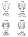
- La figure la montre, en coupe axiale, un séparateur-cyclone classique équipé d'un dispositif anti-abrasion selon l'invention; la figure lb est une demi-coupe, suivant la ligne A-A, du séparateur-cyclone représenté sur la figure la; les figures 2a et 2b, 3a et 3b, 4a et 4b, 5a et 5b sont des vues similaires aux figures la et lb, montrant quatre autres formes d'exécution de l' invention.
- The figure shows, in axial section, a conventional cyclone separator equipped with an anti-abrasion device according to the invention; Figure lb is a half-section along line AA of the cyclone separator shown in Figure la; Figures 2a and 2b, 3a and 3b, 4a and 4b, 5a and 5b are views similar to Figures la and lb, showing four other embodiments of the invention.
Le cyclone représenté sur les figures la et lb comprend un corps creux 1, par exemple en fonte, de forme cylindro-conique et d'axe vertical, ouvert à ses deux extrémités. Un tube d'évacuation 2, d'un diamètre extérieur plus petit que le diamètre intérieur du corps 1 est disposé coaxiale- ment dans l'extrémité supérieure ouverte du corps 1 et s'étend vers le bas à l'intérieur de celui-ci sur une partie de sa hauteur. Une couronne d'aubes directrices fixes 3 est fixée à l'extrémité supérieure du corps 1 dans l'espace annulaire entre ce corps 1 et le tube 2.The cyclone shown in FIGS. 1a and 1b comprises a
Le gaz G chargé de particules P est admis à grande vitesse dans le corps 1 à travers son extrémité supérieure, comme indiqué par les flèches, et il est canalisé par les aubes directrices 3 qui lui impriment un mouvement de rotation autour de l'axe du corps 1. Sous l'action de la force centrifuge, les particules P sont projetées contre la paroi interne du corps 1, le long de laquelle elles glissent vers le bas suivant un trajet approximativement hélicoïdal pour être évacuées à travers l'extrémité inférieure ouverte 4 du corps 1. Le gaz G, débarrassé des particules P est évacué à travers le tube 2.The gas G charged with particles P is admitted at high speed into the
En l'absence du dispositif anti-abrasion 5 qui va maintenant être décrit, le frottement des particules P sur la paroi interne du corps 1 use ladite paroi. Cette usure peut être considérablement réduite, voire complètement supprimée au moyen du dispositif anti-abrasion 5 conforme à l'invention qui, dans la forme d'exécution représentée sur les figures la et lb, est constitué par des barrettes 6 s'étendant dans le sens axial et pliées au profil de la paroi interne du corps 1. Les barrettes 6 sont maintenues en contact étroit avec la paroi interne du corps 1 par des anneaux de maintien 7. Le nombre des barrettes 6 et des anneaux 7 peut varier selon le diamètre intérieur et la longueur axiale du corps 1 et selon les conditions de fonctionnement.In the absence of the
Dans un dépoussiéreur multicyclone classique comprenant 60 cellules semblables à celles montrées sur les figures la et lb, et associées à un four d'incinération de déchets urbains d'une capacité nominale de 1.500 kg de déchets par heure, six des 60 cellules ont été équipées d'un dispositif anti-abrasion 5 conforme à celui montré sur les figures la et Ib. Chaque cellule avait un diamètre intérieur d'environ 250 mm. Chaque dispositif anti-abrasion 5 était constitué par quatre barrettes verticales 6 espacées circonférentiellement de 90° et par deux annéaux de maintien 7: Les quatre barrettes 6 et les deux anneaux de maintien étaient réalisés en fer rond de 10 mm. de diamètre et leur longueur totale développée était d'environ 4.000 mm. L'essai a porté sur 15.000 heures ou trois années dé fonctionnement du four à sa puissance nominale. Après 2.000 à 3.000 heures de fonctionnement, on a constaté les premiers percements des cellules non équipées du dispositif anti-abrasion 5 de l'invention. Par contre, après trois années d'utilisation, on a constaté que les six cellules équipées du dispositif anti-abrasion 5 de l'invention n'ont subi aucun dommage, ni obstruction et que le dispositif anti-abrasion 5 lui-même s'est trouvé aussi auto-protégé contre l'usure. Ceci tient au fait que les barrettes 6 retiennent une partie des particules P séparées du gaz G et permettent l'établissement d'une couche protectrice C faite desdites particules, comme montré sur la figure lb.In a conventional multicyclone dust collector comprising 60 cells similar to those shown in FIGS. 1a and 1b, and associated with an urban waste incineration oven with a nominal capacity of 1,500 kg of waste per hour, six of the 60 cells were equipped of an abrasion-
D'après ce qui précède, on voit que le dispositif anti-abrasion 5 permet d'augmenter considérablement la durée de vie des cyclones. Les essais effectués jusqu'à ce jour montrent que la durée de vie est au moins quintuplée.From the above, it can be seen that the
Le dispositif anti-abrasion 5 de l'invention est de construction très simple et peu coûteuse dans la mesure où sa fabrication nécessite seulement un petit nombre d'opérations très simples et l'utilisation d'un métal sans caractéristiques mécaniques spéciales, d'usage courant et peu onéreux. La seule précaution à prendre pour sa mise en place dans le corps 1 du cyclone est de prendre soin que les barrettes 6 soient en contact étroit avec la paroi à protéger.The abrasion-
Outre le fait que le dispositif anti-abrasion 5 de l'invention permet d'augmenter considérablement la durée de vie des cyclones, il permet également de maintenir dans le temps les performances prévues par les constructeurs, voire même d'augmenter le rendement de dépoussiérage. En effet; du fait que la couche protectrice C diminue légèrement la section de passage des gaz chargés de particules, la vitesse de ces gaz s'en trouve accélérée et la centrifugation est accrue. Par suite, la séparation des particules est améliorée et l'adhérence de la couche protectrice C sur la paroi est plus grande, ce qui améliore encore la protection contre l'usure.In addition to the fact that the
Du fait que la paroi interne du corps 1 du cyclone est parfaitement protégée contre l'usure, on peut envisager maintenant d'admettre les gaz chargés de particules dans le cyclone à des vitesses plus importantes qu'auparavant, afin d'augmenter la vitesse de centrifugation, et par suite le rendement de dépoussiérage, sans pour autant augmenter l'usure et réduire la durée de vie du cyclone. Ceci permet d'obtenir des résultats de dépoussiérage proches de ceux obtenus couramment avec des appareils plus sophistiqués comme les électro-filtres.Since the internal wall of the
Il y a lieu de noter que l'amélioration du rendement de chacune des cellules d'un tel dépoussiéreur multicyclone amène nécessairement une protection accrue de tous les matériels situés en aval du dépoussiéreur, tels que : tôleries, gaines de fumée, collecteurs, tuyauteries, appareils de contrôle, volutes et turbines de ventilateur de tirage, registre de réglage, fumisteries, cheminées, etc...It should be noted that improving the performance of each of the cells of such a multicyclone dust collector necessarily leads to increased protection of all the equipment located downstream of the dust collector, such as: sheet metal work, smoke ducts, collectors, pipes, control devices, volutes and turbines for draft fans, adjustment registers, smokehouses, chimneys, etc ...
Il y a également lieu de noter que grâce au dispositif anti-abrasion de l'invention, les opérations de remplacement des cellules endommagées sont considérablement plus espacées dans le temps, voire complètement supprimées, ce qui entraîne une économie très importante en pièces de rechange et en main-d'oeuvre et permet une utilisation plus rationnelle des fours eux-mêmes.It should also be noted that thanks to the anti- abrasion of the invention, the operations of replacing the damaged cells are considerably more spaced in time, or even completely eliminated, which results in a very significant saving in spare parts and labor and allows a more rational use of the ovens themselves.
On notera également que le dispositif anti-abrasion de l'invention.peut être mis en place dans n'importe quel type de cyclone à entrée axiale ou tangentielle, de type.vertical, horizontal ou oblique, etc... sans aucune modification des installations existantes.It will also be noted that the abrasion-resistant device of the invention can be installed in any type of cyclone with axial or tangential entry, of type vertical, horizontal or oblique, etc. without any modification of the existing facilities.
D'autre part, les cellules qui étaient jusqu'à présent fabriquées en fontes nobles et épaisses peuvent désormais être réalisées en fontes ordinaires et peu épaisses ou même en tôles fines ordinaires ou en acier inoxydable selon les applications envisagées (température, hygrométrie, acidité, etc...) .On the other hand, the cells which were hitherto manufactured in noble and thick cast irons can now be produced in ordinary and thin cast iron or even in ordinary thin sheets or in stainless steel according to the envisaged applications (temperature, hygrometry, acidity, etc ...).
Les figures 2a et 2b montrent une forme d'exécution du cyclone, dans laquelle le corps 1 est réalisé en tôle. Dans ce cas, chaque barrette 6 peut être constituée par une tôle pliée en L et fixée par l'une de ses ailes à la paroi interne du corps 1 par tout moyen approprié, par exemple par soudage par points. A la place d'une tôle pliée en L, on peut aussi utiliser des profilés en fer à section en L, en I ou en C.Figures 2a and 2b show an embodiment of the cyclone, in which the
Les figures 3a et 3b montrent une autre forme d'exécution du cyclone selon l'invention, dans laquelle le corps 1 est en fonte moulée et présente sur sa paroi interne huit nervures longitudinales (seulement cinq d'entre elles sont visibles sur les figures 3a et 3b) qui sont espacées circonférentiellement de 45° et sont formées d'une seule pièce avec le corps 1 par moulage. Les nervures 8 jouent le même rôle que les barrettes 6 des formes d'exécution précédentes.Figures 3a and 3b show another embodiment of the cyclone according to the invention, in which the
Les figures 4a et 4b montrent une autre forme d'exécution d'un cyclone, dans laquelle le corps 1 est aussi réalisé en fonte moulée. Dans ce cas, le corps 1 présente sur sa paroi interne six nervures longitudinales 8 espacées de 60° et venues de moulage avec le corps 1, ainsi que d'autres nervures 9, également venues de moulage avec le corps 1, qui s'étendent dans le sens circonférentiel et sont espacées axialement de manière à former avec les nervures 8 un quadrillage alvéolaire.Figures 4a and 4b show another embodiment of a cyclone, in which the
Les figures 5a et 5b montrent une autre forme d'exécution de l'invention dans laquelle le corps 1 est encore réalisé en fonte moulée et présente dans sa paroi interne des rainures longitudinales 10 venues de moulage. Les arêtes longitudinales 11 entre les rainures adjacentes jouent le même rôle que les barrettes 6 ou les nervures 8 des formes d'exécution précédentes.Figures 5a and 5b show another embodiment of the invention in which the
Bien que dans la description qui précède, il soit fait plus particulièrement référence au traitement des fumées d'une installation d'incinération de déchets urbains, la présente invention est applicable dans un grand nombre d'industries telles que : métallurgie, sidérurgie, verrerie, industries alimentaires, industrie du bois, industrie des matières plastiques, industrie chimique, voieries, stations d'enrobage et d'épuration, sablières, balastières, centrales thermiques, etc. En outre, le transport pneumatique, qui utilise des cyclones, devient envisageable dans les industries les plus diverses pour un grand nombre de denrées réputées abrasives, comme par exemple : poussières, suies, boues séchées, minerais, sables, gravillons, graviers, galets, farines, poudres, granulés, grains de céréales, charbons, machefers, fines, arachides, noix, coques, sciures, copeaux, ébarbages et tous produits susceptibles d'être cyclonés.Although in the above description, reference is made more particularly to the treatment of smoke from an urban waste incineration plant, the present invention is applicable in a large number of industries such as: metallurgy, steel industry, glassware, food industries, wood industry, plastics industry, chemical industry, roads, coating and purification stations, sand pits, balastières, thermal power stations, etc. In addition, pneumatic transport, which uses cyclones, becomes possible in the most diverse industries for a large number of reputable abrasive products, such as: dust, soot, dried sludge, ores, sands, gravel, gravel, pebbles, flours, powders, granules, cereal grains, coals, mints, fines, peanuts, nuts, shells, sawdust, shavings, deburring and all products liable to be cycloned.
D'après ce qui précède, il est claire que la présente invention présente un grand intérêt économique, tant par la possibilité qu'elle donne de protéger les cyclones existants avec les économies de pièces de rechange et de main- d'oeuvre qui en résultent, que par la possibilité de construire les futurs cyclones à un prix de revient plus faible, par les meilleurs résultats qu'elle procure sur le plan de la séparation des particules, par la diminution de la pollution atmosphérique par les rejets dans l'atmosphère dans les techniques de dépoussiérage, par les économies d'énergie qu'elle permet d'obtenir, et par ses nombreux domaines d'application.From the above, it is clear that the present invention is of great economic interest, both by the possibility it gives of protecting existing cyclones with the resulting savings in spare parts and labor, only by the possibility of constructing future cyclones at a lower cost price, through the best results that it provides in terms of particle separation, by reducing atmospheric pollution by discharges into the atmosphere in dust removal techniques, by the energy savings it allows, and by its many fields of application.
Il est bien entendu que les formes d'exécution qui ont été décrites ci-dessus ont été données à titre d'exemple purement indicatif et nullement limitatif, et que de nombreuses modifications peuvent être apportées facilement par l'homme de l'art sans pour autant sortir du cadre de la présente invention. C'est ainsi notamment que le nombre, la forme et la disposition des éléments en relief prévus sur la paroi interne du cyclone peut varier selon le domaine d'application, la nature du produit à traiter et les conditions de fonctionnement.It is understood that the embodiments which have been described above have been given by way of purely indicative and in no way limiting, and that numerous modifications can be easily made by those skilled in the art without as well depart from the scope of the present invention. Thus in particular that the number, the shape and the arrangement of the elements in relief provided on the internal wall of the cyclone can vary according to the field of application, the nature of the product to be treated and the operating conditions.
Claims (9)
caractérisé en ce que l'on crée sur cette paroi une couche de particules séparées du fluide en s'opposant au glissement desdites particules sur ladite paroi interne par des éléments en saillie.1. Method for protecting the inner wall of a centrifuge, with a fixed wall, against abrasion by the particles separated by centrifugation of a flow of fluid centrifuged against this wall,
characterized in that a layer of particles separated from the fluid is created on this wall by opposing the sliding of said particles on said internal wall by projecting elements.
caractérisé en ce que des éléments en relief (6,8,9,11) présentant une surface orientée au moins partiellement transversalement à la trajectoire du flux fluide sont prévus sur la surface interne de la paroi de révolution (1).2. Centrifuge for the separation of particles (P) suspended in a fluid flow (G), comprising a wall of revolution (1) and means (3) for circulating, with a rotational movement around the axis, said fluid flow in contact with the wall of revolution to centrifuge the separated particles against said wall,
characterized in that relief elements (6,8,9,11) having a surface oriented at least partially transversely to the path of the fluid flow are provided on the internal surface of the wall of revolution (1).
caractérisé en ce que les éléments en relief (6) sont amovibles et constitués par des barreaux sensiblement longitudinaux dont la forme correspond à celle de la génératrice de la paroi de révolution qui sont maintenus en contact étroit avec la surface interne de la paroi de révolution (1) et solidarisés entre eux par des barres en forme d'anneaux.3. Centrifuge according to claim 2,
characterized in that the elements in relief (6) are removable and consist of substantially longitudinal bars whose shape corresponds to that of the generator of the wall of revolution which are kept in close contact with the internal surface of the wall of revolution ( 1) and joined together by bars in the form of rings.
caractérisé en ce que les éléments en relief (6) sont constitués par des barrettes fixées sur la surface interne de la paroi de révolution (1).4. Centrifuge according to claim 2,
characterized in that the raised elements (6) consist of bars fixed to the internal surface of the wall of revolution (1).
caractérisé en ce que les éléments en relief (8,9,11) sont en une seule pièce avec la paroi de révolution (1).5. Centrifuge according to claim 2,
characterized in that the raised elements (8,9,11) are in one piece with the wall of revolution (1).
caractérisé en ce que les éléments en relief (8,9) sont constitués par des nervures venues de moulage avec la paroi de révolution (1).6. Centrifuge according to claim 5,
characterized in that the elements in relief (8, 9) consist of ribs coming from molding with the wall of revolution (1).
caractérisé.en ce que les éléments en relief (11) sont constitués par des arêtes entre des rainures (10) formées dans la surface interne de la paroi de révolution (1).7. Centrifuge according to claim-5,
characterized.in that the raised elements (11) consist of edges between grooves (10) formed in the internal surface of the wall of revolution (1).
caractérisé en ce que d'autres éléments en relief (9) s'étendent dans le sens circonférentiel et sont espacés axialement de manière à former un quadrillage alvéolaire avec les éléments en relief (8) qui s'étendent dans le sens axial.9. Centrifuge according to claim 8,
characterized in that other raised elements (9) extend in the circumferential direction and are spaced axially so as to form a cellular grid with the raised elements (8) which extend in the axial direction.
Applications Claiming Priority (2)
| Application Number | Priority Date | Filing Date | Title |
|---|---|---|---|
| FR8023691 | 1980-11-06 | ||
| FR8023691A FR2493186B1 (en) | 1980-11-06 | 1980-11-06 | CENTRIFUGAL WITH ANTI-ABRASION DEVICE FOR THE SEPARATION OF PARTICLES SUSPENDED IN A GASEOUS FLUID |
Publications (2)
| Publication Number | Publication Date |
|---|---|
| EP0052042A2 true EP0052042A2 (en) | 1982-05-19 |
| EP0052042A3 EP0052042A3 (en) | 1983-01-05 |
Family
ID=9247729
Family Applications (1)
| Application Number | Title | Priority Date | Filing Date |
|---|---|---|---|
| EP81401689A Ceased EP0052042A3 (en) | 1980-11-06 | 1981-10-23 | Protection of the wall of a centrifugal separator against abrasion by particles separated by centrifugation, and device for carrying out the method |
Country Status (3)
| Country | Link |
|---|---|
| EP (1) | EP0052042A3 (en) |
| JP (1) | JPS57107253A (en) |
| FR (1) | FR2493186B1 (en) |
Cited By (7)
| Publication number | Priority date | Publication date | Assignee | Title |
|---|---|---|---|---|
| EP0763384A1 (en) * | 1995-09-15 | 1997-03-19 | GEC ALSTHOM Stein Industrie | Centrifugal separator, in particular for a circulating fluidized bed boiler |
| RU2224599C1 (en) * | 2002-01-29 | 2004-02-27 | Сергей Николаевич Кущенко | Cyclone housing and method of manufacture of such housing |
| WO2004009244A3 (en) * | 2002-07-19 | 2004-06-10 | Shell Oil Co | Cyclone separator with a vortex extender pin |
| RU2234985C1 (en) * | 2002-03-22 | 2004-08-27 | Сергей Николаевич Кущенко | Cyclone casing and method for manufacture of cyclone casing |
| US7648544B2 (en) | 2002-07-19 | 2010-01-19 | Shell Oil Company | Swirl tube separator |
| US8287613B2 (en) | 2007-06-01 | 2012-10-16 | Shell Oil Company | Gas-solids separator |
| WO2013042084A3 (en) * | 2011-09-22 | 2013-05-30 | Cydaf Technologies Limited | Apparatus for separation and processing of materials |
Families Citing this family (2)
| Publication number | Priority date | Publication date | Assignee | Title |
|---|---|---|---|---|
| JPS57190655A (en) * | 1981-05-20 | 1982-11-24 | Babcock Hitachi Kk | Coal crusher |
| WO2013012003A1 (en) * | 2011-07-19 | 2013-01-24 | 株式会社コガネイ | Filter |
Family Cites Families (4)
| Publication number | Priority date | Publication date | Assignee | Title |
|---|---|---|---|---|
| BE420877A (en) * | 1936-03-11 | |||
| FR1507938A (en) * | 1967-01-19 | 1967-12-29 | Beloit Corp | Method and device for centrifugal separation of particles in a fluid mixture |
| US3902601A (en) * | 1974-03-14 | 1975-09-02 | Townley Ind Plastics Inc | One piece cyclone cone |
| US4153558A (en) * | 1978-03-08 | 1979-05-08 | Ab Celleco | Hydrocyclone separator |
-
1980
- 1980-11-06 FR FR8023691A patent/FR2493186B1/en not_active Expired
-
1981
- 1981-10-23 EP EP81401689A patent/EP0052042A3/en not_active Ceased
- 1981-11-02 JP JP17468981A patent/JPS57107253A/en active Pending
Cited By (9)
| Publication number | Priority date | Publication date | Assignee | Title |
|---|---|---|---|---|
| EP0763384A1 (en) * | 1995-09-15 | 1997-03-19 | GEC ALSTHOM Stein Industrie | Centrifugal separator, in particular for a circulating fluidized bed boiler |
| RU2224599C1 (en) * | 2002-01-29 | 2004-02-27 | Сергей Николаевич Кущенко | Cyclone housing and method of manufacture of such housing |
| RU2234985C1 (en) * | 2002-03-22 | 2004-08-27 | Сергей Николаевич Кущенко | Cyclone casing and method for manufacture of cyclone casing |
| WO2004009244A3 (en) * | 2002-07-19 | 2004-06-10 | Shell Oil Co | Cyclone separator with a vortex extender pin |
| CN100415381C (en) * | 2002-07-19 | 2008-09-03 | 国际壳牌研究有限公司 | Vortex tube separator, multistage separator, and method of separating solids and gases to obtain a gaseous stream |
| US7648544B2 (en) | 2002-07-19 | 2010-01-19 | Shell Oil Company | Swirl tube separator |
| US8287613B2 (en) | 2007-06-01 | 2012-10-16 | Shell Oil Company | Gas-solids separator |
| WO2013042084A3 (en) * | 2011-09-22 | 2013-05-30 | Cydaf Technologies Limited | Apparatus for separation and processing of materials |
| US9370753B2 (en) | 2011-09-22 | 2016-06-21 | Cydaf Technologies Limited | Apparatus for separation and processing of materials |
Also Published As
| Publication number | Publication date |
|---|---|
| FR2493186B1 (en) | 1985-07-12 |
| FR2493186A1 (en) | 1982-05-07 |
| EP0052042A3 (en) | 1983-01-05 |
| JPS57107253A (en) | 1982-07-03 |
Similar Documents
| Publication | Publication Date | Title |
|---|---|---|
| EP0476496B1 (en) | Process for fabrication of a bimetallic casting and a wear resisting part according to said process | |
| EP0052042A2 (en) | Protection of the wall of a centrifugal separator against abrasion by particles separated by centrifugation, and device for carrying out the method | |
| CA2984710C (en) | Cracking furnace | |
| EP1846721A1 (en) | Device for extracting heat from gas and for recovering condensates | |
| EP2776540A1 (en) | Reactor for drying and torrefying a biomass, preferably a lignocellulose biomass | |
| EP0396463B1 (en) | High-intensity magnetic separator | |
| FR2568307A1 (en) | IMPROVED STAGE FOR STEAM TURBINE | |
| FR2610217A1 (en) | ROTARY CRUSHER WITH SELF-DIRECTED PROJECTION AUBES | |
| CN1650041A (en) | Abrasion resistant surface treatment method of a rotary member, runner, and fluid machine having runner | |
| EP0165224B1 (en) | Apparatus for direct firing | |
| CN102861677A (en) | High-intensity wear-resistant and corrosion-resistant spiral discharging sedimentation centrifuge and manufacturing process therefore | |
| FR2668774A1 (en) | METHOD AND DEVICE FOR PRODUCING SOLID FUEL FROM COMBUSTIBLE WASTE. | |
| FR2489169A1 (en) | DEVICE FOR SEPARATING OR ENRICHING GASEOUS MIXTURES | |
| FR2790545A1 (en) | Unit for extraction of heat from dust-containing hot gas, such as glass melting furnace combustion gas, includes device for creating helicoidally rotating gas current in a heat exchanger | |
| FR2482874A1 (en) | CENTRIFUGAL BOWL END CLOSURE FIXING FLANGES | |
| EP3885651B1 (en) | Rotary de-ashing grate system for furnace of a combustion or gasification installation | |
| FR2790544A1 (en) | Unit for extraction of heat from dust-containing hot gas, such as glass melting furnace combustion gas, includes device for creating helicoidally rotating gas current in a heat exchanger | |
| EP4028692B1 (en) | Method and furnace for incinerating organic matter derived from the treatment of industrial or agricultural waste or wastewater, such as sludge | |
| BE899562A (en) | Equipment for direct heating by combustion - makes direct use of moist fuel without intermediate drying, burnt upstream of combustion chamber | |
| EP1241682B1 (en) | Nuclear reactor coolant pump | |
| EP0623374A1 (en) | Centrifugal separator for fluids | |
| BE485255A (en) | ||
| CH716145A2 (en) | Method and device for thermal treatment of urban waste. | |
| BE464228A (en) | ||
| KR20170026122A (en) | Heat Storage Type Combustion System Equiped with Disk-type Distributor Having Excellent Sealing |
Legal Events
| Date | Code | Title | Description |
|---|---|---|---|
| PUAI | Public reference made under article 153(3) epc to a published international application that has entered the european phase |
Free format text: ORIGINAL CODE: 0009012 |
|
| AK | Designated contracting states |
Designated state(s): AT BE CH DE GB IT LU NL SE |
|
| PUAL | Search report despatched |
Free format text: ORIGINAL CODE: 0009013 |
|
| AK | Designated contracting states |
Designated state(s): AT BE CH DE GB IT LI LU NL SE |
|
| 17P | Request for examination filed |
Effective date: 19830630 |
|
| STAA | Information on the status of an ep patent application or granted ep patent |
Free format text: STATUS: THE APPLICATION HAS BEEN REFUSED |
|
| 18R | Application refused |
Effective date: 19850223 |