EP0052542B1 - Elektrochemischer Messfühler zum Bestimmen der Gaskonzentration in einem Gemisch und Regelungsvorrichtung für das Luft-Brennstoff-Verhältnis mit diesem Messfühler - Google Patents
Elektrochemischer Messfühler zum Bestimmen der Gaskonzentration in einem Gemisch und Regelungsvorrichtung für das Luft-Brennstoff-Verhältnis mit diesem Messfühler Download PDFInfo
- Publication number
- EP0052542B1 EP0052542B1 EP81401648A EP81401648A EP0052542B1 EP 0052542 B1 EP0052542 B1 EP 0052542B1 EP 81401648 A EP81401648 A EP 81401648A EP 81401648 A EP81401648 A EP 81401648A EP 0052542 B1 EP0052542 B1 EP 0052542B1
- Authority
- EP
- European Patent Office
- Prior art keywords
- region
- reactive species
- electrode
- probe
- admitted
- Prior art date
- Legal status (The legal status is an assumption and is not a legal conclusion. Google has not performed a legal analysis and makes no representation as to the accuracy of the status listed.)
- Expired
Links
- 239000000203 mixture Substances 0.000 title claims abstract description 99
- 239000007789 gas Substances 0.000 title claims description 58
- 239000000446 fuel Substances 0.000 title claims description 21
- 239000012530 fluid Substances 0.000 claims abstract description 28
- 238000006555 catalytic reaction Methods 0.000 claims abstract description 16
- 230000036961 partial effect Effects 0.000 claims abstract description 8
- 150000002500 ions Chemical class 0.000 claims description 51
- 229910052760 oxygen Inorganic materials 0.000 claims description 42
- 238000005259 measurement Methods 0.000 claims description 41
- 239000001301 oxygen Substances 0.000 claims description 41
- QVGXLLKOCUKJST-UHFFFAOYSA-N atomic oxygen Chemical compound [O] QVGXLLKOCUKJST-UHFFFAOYSA-N 0.000 claims description 39
- 239000007784 solid electrolyte Substances 0.000 claims description 24
- 239000003792 electrolyte Substances 0.000 claims description 19
- BASFCYQUMIYNBI-UHFFFAOYSA-N platinum Chemical compound [Pt] BASFCYQUMIYNBI-UHFFFAOYSA-N 0.000 claims description 16
- 230000004044 response Effects 0.000 claims description 16
- 239000000463 material Substances 0.000 claims description 12
- 238000002485 combustion reaction Methods 0.000 claims description 10
- MCMNRKCIXSYSNV-UHFFFAOYSA-N Zirconium dioxide Chemical compound O=[Zr]=O MCMNRKCIXSYSNV-UHFFFAOYSA-N 0.000 claims description 8
- 238000006243 chemical reaction Methods 0.000 claims description 8
- 238000002848 electrochemical method Methods 0.000 claims description 8
- 229910052751 metal Inorganic materials 0.000 claims description 7
- 239000002184 metal Substances 0.000 claims description 7
- 229910052697 platinum Inorganic materials 0.000 claims description 6
- 239000011148 porous material Substances 0.000 claims description 5
- 238000004891 communication Methods 0.000 claims description 4
- 238000001514 detection method Methods 0.000 claims description 4
- 230000002829 reductive effect Effects 0.000 claims description 4
- BQCADISMDOOEFD-UHFFFAOYSA-N Silver Chemical compound [Ag] BQCADISMDOOEFD-UHFFFAOYSA-N 0.000 claims description 3
- 238000002347 injection Methods 0.000 claims description 3
- 239000007924 injection Substances 0.000 claims description 3
- 229910044991 metal oxide Inorganic materials 0.000 claims description 3
- 230000000737 periodic effect Effects 0.000 claims description 3
- 229910052684 Cerium Inorganic materials 0.000 claims description 2
- 229910000422 cerium(IV) oxide Inorganic materials 0.000 claims description 2
- 238000010438 heat treatment Methods 0.000 claims description 2
- 150000002739 metals Chemical class 0.000 claims description 2
- 229910052709 silver Inorganic materials 0.000 claims description 2
- 239000004332 silver Substances 0.000 claims description 2
- 239000000523 sample Substances 0.000 claims 20
- 230000003197 catalytic effect Effects 0.000 claims 3
- XEEYBQQBJWHFJM-UHFFFAOYSA-N Iron Chemical compound [Fe] XEEYBQQBJWHFJM-UHFFFAOYSA-N 0.000 claims 2
- PXHVJJICTQNCMI-UHFFFAOYSA-N Nickel Chemical compound [Ni] PXHVJJICTQNCMI-UHFFFAOYSA-N 0.000 claims 2
- 150000001875 compounds Chemical class 0.000 claims 2
- 238000000605 extraction Methods 0.000 claims 2
- VYZAMTAEIAYCRO-UHFFFAOYSA-N Chromium Chemical compound [Cr] VYZAMTAEIAYCRO-UHFFFAOYSA-N 0.000 claims 1
- RYGMFSIKBFXOCR-UHFFFAOYSA-N Copper Chemical compound [Cu] RYGMFSIKBFXOCR-UHFFFAOYSA-N 0.000 claims 1
- RTAQQCXQSZGOHL-UHFFFAOYSA-N Titanium Chemical compound [Ti] RTAQQCXQSZGOHL-UHFFFAOYSA-N 0.000 claims 1
- HCHKCACWOHOZIP-UHFFFAOYSA-N Zinc Chemical compound [Zn] HCHKCACWOHOZIP-UHFFFAOYSA-N 0.000 claims 1
- 238000009529 body temperature measurement Methods 0.000 claims 1
- CETPSERCERDGAM-UHFFFAOYSA-N ceric oxide Chemical compound O=[Ce]=O CETPSERCERDGAM-UHFFFAOYSA-N 0.000 claims 1
- ZMIGMASIKSOYAM-UHFFFAOYSA-N cerium Chemical compound [Ce][Ce][Ce][Ce][Ce][Ce][Ce][Ce][Ce][Ce][Ce][Ce][Ce][Ce][Ce][Ce][Ce][Ce][Ce][Ce][Ce][Ce][Ce][Ce][Ce][Ce][Ce][Ce][Ce][Ce][Ce][Ce][Ce][Ce][Ce][Ce][Ce][Ce] ZMIGMASIKSOYAM-UHFFFAOYSA-N 0.000 claims 1
- 229910052804 chromium Inorganic materials 0.000 claims 1
- 239000011651 chromium Substances 0.000 claims 1
- 229910017052 cobalt Inorganic materials 0.000 claims 1
- 239000010941 cobalt Substances 0.000 claims 1
- GUTLYIVDDKVIGB-UHFFFAOYSA-N cobalt atom Chemical compound [Co] GUTLYIVDDKVIGB-UHFFFAOYSA-N 0.000 claims 1
- 239000004020 conductor Substances 0.000 claims 1
- 229910052802 copper Inorganic materials 0.000 claims 1
- 239000010949 copper Substances 0.000 claims 1
- 238000000840 electrochemical analysis Methods 0.000 claims 1
- 230000001939 inductive effect Effects 0.000 claims 1
- 229910052742 iron Inorganic materials 0.000 claims 1
- 239000011133 lead Substances 0.000 claims 1
- WPBNNNQJVZRUHP-UHFFFAOYSA-L manganese(2+);methyl n-[[2-(methoxycarbonylcarbamothioylamino)phenyl]carbamothioyl]carbamate;n-[2-(sulfidocarbothioylamino)ethyl]carbamodithioate Chemical compound [Mn+2].[S-]C(=S)NCCNC([S-])=S.COC(=O)NC(=S)NC1=CC=CC=C1NC(=S)NC(=O)OC WPBNNNQJVZRUHP-UHFFFAOYSA-L 0.000 claims 1
- 229910052759 nickel Inorganic materials 0.000 claims 1
- 229910003446 platinum oxide Inorganic materials 0.000 claims 1
- ZCUFMDLYAMJYST-UHFFFAOYSA-N thorium dioxide Chemical compound O=[Th]=O ZCUFMDLYAMJYST-UHFFFAOYSA-N 0.000 claims 1
- 239000010936 titanium Substances 0.000 claims 1
- 229910052719 titanium Inorganic materials 0.000 claims 1
- 229910052720 vanadium Inorganic materials 0.000 claims 1
- GPPXJZIENCGNKB-UHFFFAOYSA-N vanadium Chemical compound [V]#[V] GPPXJZIENCGNKB-UHFFFAOYSA-N 0.000 claims 1
- 238000004804 winding Methods 0.000 claims 1
- 229910052725 zinc Inorganic materials 0.000 claims 1
- 239000011701 zinc Substances 0.000 claims 1
- 238000000034 method Methods 0.000 abstract description 17
- 239000008246 gaseous mixture Substances 0.000 abstract description 11
- 230000008569 process Effects 0.000 abstract description 2
- 238000003556 assay Methods 0.000 abstract 1
- 238000013459 approach Methods 0.000 description 29
- 238000005086 pumping Methods 0.000 description 25
- 238000012360 testing method Methods 0.000 description 19
- 230000006870 function Effects 0.000 description 16
- 108010083687 Ion Pumps Proteins 0.000 description 15
- 230000001105 regulatory effect Effects 0.000 description 12
- 239000000758 substrate Substances 0.000 description 10
- 239000003054 catalyst Substances 0.000 description 7
- 229910002091 carbon monoxide Inorganic materials 0.000 description 6
- 239000013626 chemical specie Substances 0.000 description 6
- 210000003298 dental enamel Anatomy 0.000 description 6
- UGFAIRIUMAVXCW-UHFFFAOYSA-N Carbon monoxide Chemical compound [O+]#[C-] UGFAIRIUMAVXCW-UHFFFAOYSA-N 0.000 description 5
- 230000008901 benefit Effects 0.000 description 5
- 230000000670 limiting effect Effects 0.000 description 5
- 238000004519 manufacturing process Methods 0.000 description 5
- HIGRAKVNKLCVCA-UHFFFAOYSA-N alumine Chemical compound C1=CC=[Al]C=C1 HIGRAKVNKLCVCA-UHFFFAOYSA-N 0.000 description 4
- PNEYBMLMFCGWSK-UHFFFAOYSA-N aluminium oxide Inorganic materials [O-2].[O-2].[O-2].[Al+3].[Al+3] PNEYBMLMFCGWSK-UHFFFAOYSA-N 0.000 description 4
- 230000001419 dependent effect Effects 0.000 description 4
- 239000012212 insulator Substances 0.000 description 4
- 238000012546 transfer Methods 0.000 description 4
- 230000006978 adaptation Effects 0.000 description 3
- 239000000470 constituent Substances 0.000 description 3
- 238000000151 deposition Methods 0.000 description 3
- 230000000694 effects Effects 0.000 description 3
- 238000004377 microelectronic Methods 0.000 description 3
- 210000000056 organ Anatomy 0.000 description 3
- 239000010453 quartz Substances 0.000 description 3
- VYPSYNLAJGMNEJ-UHFFFAOYSA-N silicon dioxide Inorganic materials O=[Si]=O VYPSYNLAJGMNEJ-UHFFFAOYSA-N 0.000 description 3
- 208000031968 Cadaver Diseases 0.000 description 2
- CURLTUGMZLYLDI-UHFFFAOYSA-N Carbon dioxide Chemical compound O=C=O CURLTUGMZLYLDI-UHFFFAOYSA-N 0.000 description 2
- 238000004458 analytical method Methods 0.000 description 2
- 229910002092 carbon dioxide Inorganic materials 0.000 description 2
- 239000000919 ceramic Substances 0.000 description 2
- 230000008859 change Effects 0.000 description 2
- 230000001276 controlling effect Effects 0.000 description 2
- 239000010431 corundum Substances 0.000 description 2
- 229910052593 corundum Inorganic materials 0.000 description 2
- 238000010586 diagram Methods 0.000 description 2
- 230000006872 improvement Effects 0.000 description 2
- 239000010416 ion conductor Substances 0.000 description 2
- 239000004922 lacquer Substances 0.000 description 2
- 230000000873 masking effect Effects 0.000 description 2
- 150000004706 metal oxides Chemical class 0.000 description 2
- -1 oxygen ion Chemical class 0.000 description 2
- 230000003071 parasitic effect Effects 0.000 description 2
- 230000001681 protective effect Effects 0.000 description 2
- 230000002441 reversible effect Effects 0.000 description 2
- 238000011144 upstream manufacturing Methods 0.000 description 2
- MYMOFIZGZYHOMD-UHFFFAOYSA-N Dioxygen Chemical compound O=O MYMOFIZGZYHOMD-UHFFFAOYSA-N 0.000 description 1
- 102000006391 Ion Pumps Human genes 0.000 description 1
- 229910052581 Si3N4 Inorganic materials 0.000 description 1
- XUIMIQQOPSSXEZ-UHFFFAOYSA-N Silicon Chemical compound [Si] XUIMIQQOPSSXEZ-UHFFFAOYSA-N 0.000 description 1
- JISVROCKRBFEIQ-UHFFFAOYSA-N [O].O=[C] Chemical compound [O].O=[C] JISVROCKRBFEIQ-UHFFFAOYSA-N 0.000 description 1
- 230000009471 action Effects 0.000 description 1
- 239000000956 alloy Substances 0.000 description 1
- 229910045601 alloy Inorganic materials 0.000 description 1
- 230000015572 biosynthetic process Effects 0.000 description 1
- 238000004364 calculation method Methods 0.000 description 1
- 239000001569 carbon dioxide Substances 0.000 description 1
- GWXLDORMOJMVQZ-UHFFFAOYSA-N cerium Chemical compound [Ce] GWXLDORMOJMVQZ-UHFFFAOYSA-N 0.000 description 1
- 229910000420 cerium oxide Inorganic materials 0.000 description 1
- 239000001679 citrus red 2 Substances 0.000 description 1
- 230000036461 convulsion Effects 0.000 description 1
- NFFYXVOHHLQALV-UHFFFAOYSA-N copper(III) oxide Inorganic materials [O-2].[O-2].[O-2].[Cu].[Cu] NFFYXVOHHLQALV-UHFFFAOYSA-N 0.000 description 1
- 230000008878 coupling Effects 0.000 description 1
- 238000010168 coupling process Methods 0.000 description 1
- 238000005859 coupling reaction Methods 0.000 description 1
- 230000008021 deposition Effects 0.000 description 1
- 229910001882 dioxygen Inorganic materials 0.000 description 1
- 238000003487 electrochemical reaction Methods 0.000 description 1
- 230000005518 electrochemistry Effects 0.000 description 1
- 238000004070 electrodeposition Methods 0.000 description 1
- 239000002320 enamel (paints) Substances 0.000 description 1
- 229940082150 encore Drugs 0.000 description 1
- 238000005516 engineering process Methods 0.000 description 1
- 230000008020 evaporation Effects 0.000 description 1
- 238000001704 evaporation Methods 0.000 description 1
- 239000010408 film Substances 0.000 description 1
- PCHJSUWPFVWCPO-UHFFFAOYSA-N gold Chemical compound [Au] PCHJSUWPFVWCPO-UHFFFAOYSA-N 0.000 description 1
- 229910052737 gold Inorganic materials 0.000 description 1
- 239000010931 gold Substances 0.000 description 1
- 229910052736 halogen Chemical group 0.000 description 1
- 150000002367 halogens Chemical group 0.000 description 1
- 230000036541 health Effects 0.000 description 1
- 239000011810 insulating material Substances 0.000 description 1
- 230000003993 interaction Effects 0.000 description 1
- 238000005468 ion implantation Methods 0.000 description 1
- NUJOXMJBOLGQSY-UHFFFAOYSA-N manganese dioxide Inorganic materials O=[Mn]=O NUJOXMJBOLGQSY-UHFFFAOYSA-N 0.000 description 1
- GEYXPJBPASPPLI-UHFFFAOYSA-N manganese(III) oxide Inorganic materials O=[Mn]O[Mn]=O GEYXPJBPASPPLI-UHFFFAOYSA-N 0.000 description 1
- 239000012528 membrane Substances 0.000 description 1
- 238000002156 mixing Methods 0.000 description 1
- 150000004767 nitrides Chemical class 0.000 description 1
- 239000000615 nonconductor Substances 0.000 description 1
- BMMGVYCKOGBVEV-UHFFFAOYSA-N oxo(oxoceriooxy)cerium Chemical compound [Ce]=O.O=[Ce]=O BMMGVYCKOGBVEV-UHFFFAOYSA-N 0.000 description 1
- 150000002926 oxygen Chemical class 0.000 description 1
- 239000004175 ponceau 4R Substances 0.000 description 1
- 230000000717 retained effect Effects 0.000 description 1
- 238000012552 review Methods 0.000 description 1
- 229910052594 sapphire Inorganic materials 0.000 description 1
- 239000010980 sapphire Substances 0.000 description 1
- 238000007650 screen-printing Methods 0.000 description 1
- 230000035945 sensitivity Effects 0.000 description 1
- HQVNEWCFYHHQES-UHFFFAOYSA-N silicon nitride Chemical compound N12[Si]34N5[Si]62N3[Si]51N64 HQVNEWCFYHHQES-UHFFFAOYSA-N 0.000 description 1
- 239000007787 solid Substances 0.000 description 1
- 239000011343 solid material Substances 0.000 description 1
- 239000000243 solution Substances 0.000 description 1
- 238000004544 sputter deposition Methods 0.000 description 1
- 239000010409 thin film Substances 0.000 description 1
- 210000002105 tongue Anatomy 0.000 description 1
- 238000001771 vacuum deposition Methods 0.000 description 1
- 238000007740 vapor deposition Methods 0.000 description 1
- XLOMVQKBTHCTTD-UHFFFAOYSA-N zinc oxide Inorganic materials [Zn]=O XLOMVQKBTHCTTD-UHFFFAOYSA-N 0.000 description 1
Images


Classifications
-
- G—PHYSICS
- G01—MEASURING; TESTING
- G01N—INVESTIGATING OR ANALYSING MATERIALS BY DETERMINING THEIR CHEMICAL OR PHYSICAL PROPERTIES
- G01N27/00—Investigating or analysing materials by the use of electric, electrochemical, or magnetic means
- G01N27/26—Investigating or analysing materials by the use of electric, electrochemical, or magnetic means by investigating electrochemical variables; by using electrolysis or electrophoresis
- G01N27/403—Cells and electrode assemblies
- G01N27/406—Cells and probes with solid electrolytes
- G01N27/407—Cells and probes with solid electrolytes for investigating or analysing gases
- G01N27/4071—Cells and probes with solid electrolytes for investigating or analysing gases using sensor elements of laminated structure
-
- G—PHYSICS
- G01—MEASURING; TESTING
- G01N—INVESTIGATING OR ANALYSING MATERIALS BY DETERMINING THEIR CHEMICAL OR PHYSICAL PROPERTIES
- G01N27/00—Investigating or analysing materials by the use of electric, electrochemical, or magnetic means
- G01N27/26—Investigating or analysing materials by the use of electric, electrochemical, or magnetic means by investigating electrochemical variables; by using electrolysis or electrophoresis
- G01N27/416—Systems
- G01N27/417—Systems using cells, i.e. more than one cell and probes with solid electrolytes
Definitions
- the invention relates to electrochemical sensors for the concentrations of species in a fluid mixture and in particular to a system for regulating the richness of a gaseous air-fuel mixture.
- Recent approaches for producing sensors propose the use of a means combining the electrode function and the reference medium function.
- an electrode based on a combination of the type is used: M-MX where M is a metal and X is oxygen or a halogen to be detected (for example M-MO in the case of detection of the oxygen).
- M-MX an electrode based on a combination of the type
- X oxygen or a halogen to be detected
- sensors have also been proposed produced according to the thin film technique used in microelectronics.
- the invention relates to sensors of the type comprising electrodes or other means placed upstream of the electrochemical measurement cell carrying out the complete catalysis, so that the gas mixture to be analyzed reaches thermodynamic equilibrium at least at the electrode-electrolyte interface and one of the electrodes of which is of the type described above based on an M-MX combination.
- Such sensors are commonly used for regulating internal combustion engines and in particular for regulating the admission of the air-fuel mixture to the carburetor or the fuel injector.
- the sensor is then placed in the exhaust circuit and analyzes the relative concentration of the oxygen-carbon monoxide species contained in the gas.
- the sensor must then be adapted to certain characteristics specific to this use. Indeed the exhaust gas will arrive in jerks, at the rate of the reciprocating movement of the different pistons.
- the electrode is in the form of a layer of porous catalyst material and the gas to be analyzed propagates within it in a direction parallel to the largest dimensions of the electrode before reaching the actual measurement area.
- a sensor is described in European patent applications EP-A-00110 38 and EP-A-0-012647.
- sensors can be used as they are in certain countries, in particular in countries imposing strict anti-pollution standards.
- the engine then operates with a stoichiometric air-fuel mixture.
- the "transfer impedance" as defined above is made selective by the use of a porous material specially adapted to the fluid to be analyzed.
- a mixture composition given at the input of the sensor can correspond to a different mixture composition within the porous material and then at the level of the measurement electrode.
- the apparent concentration of the species of a gas mixture is measured, that is to say that which exists at the level of the measurement electrode, and by this the regulation point is shifted on either side of the stoichiometry of the gaseous mixture actually circulating in the exhaust ducts.
- a regulation system using this type of sensor is less dependent on the effects of temperature since in this case the tilting of the response curve is also detected. , tilting which occurs on either side of the stoichiometry according to the nature 1 "'transfer impedance", ie in a region of the curve less sensitive to this parameter.
- the amplitude of the offset allowed by these devices is relatively limited and fixed once all at a predetermined value at the time of manufacture.
- the invention aims to fill this need by using a sensor structure incorporating a member of the ion pump type making it possible to continuously change the concentration. apparent relative measured at the measurement electrode, using an electronic control current.
- This type of organ is used in the known art to regulate the concentration of a chemical species in an enclosure or a pipe, for example oxygen, by carrying out a reversible pumping of this species contained in a second reservoir enclosure.
- An ion pump generally has a structure analogous to that of an electrochemical cell: a membrane constituted by a solid electrolyte permeable to ions of the chemical species to be "pumped" comprising on its two faces electrodes connected to the terminals of a source of electronic current. Depending on the amplitude and the polarity of the current, an ion current is established within the electrolyte resulting in the transport of ions of the species which recombine on one of the two electrodes according to the direction of conduction. In the case of oxygen, the relation (1) previously recalled is satisfied.
- Such ion pumps are also used in devices for measuring the quantity of oxygen included in a sample of a gaseous mixture admitted into a measurement enclosure.
- the method used consists in separating the oxygen from the other chemical species included in the mixture. To do this, the ion pump pumps oxygen out of the enclosure through a solid ionic conductor of oxygen ion.
- the amount of oxygen present in the gas mixture can be determined by measuring the amount of electrical charge supplied to the ion pump to extract this oxygen from the enclosure.
- Measuring devices of this type are also provided with an electrochemical measurement cell measuring a low oxygen concentration in the measurement enclosure. This measurement is carried out by detecting a large potential difference across the terminals of the measurement cell of determined amplitude.
- the subject of the invention is therefore an electrochemical sensor as specified in claims 1 or 3.
- the subject of the invention is also a system for regulating the richness of the air-fuel mixture of a combustion engine using a sensor as specified in claims 1 to 11, said system being defined in claim 12.
- FIG. 1 describes an example of a sensor structure of the prior art, simultaneously incorporating the functions of "test portion", of catalysis and of measurement proper and produced according to the deposition techniques in thin layer or in thick layer.
- test portion of catalysis
- measurement proper produced according to the deposition techniques in thin layer or in thick layer.
- electrochemical sensors described are intended for the detection of the relative concentrations of oxygen and carbon monoxide, without this being limiting the scope of the invention.
- the main characteristics of such a sensor will be recalled in the following by way of illustration of the known art.
- the sensor of FIG. 1 comprises two electrodes deposited on a solid electrolyte E, itself deposited on the substrate Sb.
- the electrodes E 1 / P 1 and E 2 are located in the same plane.
- the E 1 / P 1 electrode combines the functions of electrode and reference medium.
- the electrode E 1 / P j is further protected from the external environment by a waterproof and inert insulator S 1 , which covers it. An association of the Ni / Ni 0 type can be used to produce this reference electrode-medium.
- the electrode E 2 has two zones and communicates directly with the medium to be analyzed Mex in which the gas mixture G circulates through an orifice made in the insulating body S 1 which also covers it.
- the electrode In the first zone Ct, the electrode is isolated on its underside from the electrolyte E l by an insulating body S 2 of the same type as S 1 , over a length 1 c .
- the fluid to be analyzed must pass through the body C t which is a catalyst.
- the reactive species of the mixture to be analyzed (for example, in the case of exhaust gases: CO and O 2 ) are brought to complete thermodynamic equilibrium before they reach the electrochemical cell proper:
- the area C t is not that the extension of the electrode E 2 / P 2 and consists of the same material, for example platinum, deposited in a thin layer.
- the catalysis is carried out by the fluid passing through the catalyst in a direction parallel to the plane of the electrodes.
- the electrodes are extended towards the outside by metal connections on which the contacts Ci and C 2 can be welded, connections which are produced in platinum lacquer for example.
- the substrate S b can be constituted by a good insulator at the operating temperature of the device (corundum for example) and ensures the mechanical strength of the assembly. This substrate can be extended in any direction to be adapted to means for fixing to a housing.
- the solid electrolyte can consist of a thick plate and the substrate does not exist.
- Deposits can be carried out by well-known techniques, such as: vacuum deposition (sputtering, evaporation), vapor deposition, electrochemical deposition or ion implantation or by a combination of two or more of these techniques.
- FIG. 2 illustrates a set of response curves of the oxygen concentration sensors of the prior art in the exhaust gases of an internal combustion engine.
- Each curve represents the difference in inter-electrode potential V E1 / E2 as a function of the concentration of oxygen in the exhaust gases, at constant temperature.
- zones 1 and III the different curves are clearly differentiated from each other. Indeed, if we refer to the relations (2) and (4) recalled above, we note that these relations both contain the parameter "absolute temperature T". It is therefore difficult to exploit these parts of the curves, because the exhaust gases do not have a constant temperature.
- zone II of FIG. 2 which corresponds to the tilting, the different curves are practically combined. Also only this area is usually exploited.
- the output of the sensor is transmitted to an electrical control member (not shown) which detects the rapid tilting of the curve V E1 / E2 around the abscissa point ⁇ s , which represents the stoichiometric ratio of the mixture, as it is measured at the measuring electrode E 2 / P 1 .
- the tipping point is fixed, even if it is possible by the method described in the above-mentioned European patent application EP-A-0011530 to shift this tipping point slightly on either side of the stoichiometry.
- the structure of the sensor incorporates an additional cell analogous to the measurement cell E 1 -E 1 -E 2 operating as an ion pump, and which will be called in the following ion pumping cell.
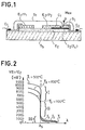
- a tell ion pump is described schematically in Figure 3. It is substantially in the form of an electrochemical cell comprising a solid electrolyte E, the ion conductor of at least one specific chemical species, for example oxygen, annular shape in the example chosen on the inner and outer faces of which has been deposited a pair of electrodes, E 1 'and E 2 ' respectively.
- an ion current is created within the electrolyte, that is to say a transport of ions of the species considered from the electrode E 2 'to the electrode E 1 ' or vice versa, the amplitude of this ion current being linked by a determined law to the amplitude of the control voltage V c .
- the electrodes must be porous or permeable to the determined chemical species.
- the example of oxygen will be considered in what follows, it being understood that the oxygen can be pure or be included in a mixture of various fluids.
- the ion current within the electrolyte results in an electronic current i in the electrical circuit outside the cell. The current i can deduce from the above relation (1).
- the cell develops an own counter-electromotive force V E1 / E2 given by the law of NERNST and explained by the relation (2).
- Z el is the impedance of the solid electrolyte E, 'opposing the ionic conduction which is reduced as a first approximation to a resistance R el which depends on the characteristics dimensions of the solid electrolyte and its ionic conductivity at a given temperature.
- P 1 and P 2 are the partial pressures of media 1 and II respectively
- medium II can be considered as a reservoir medium containing at least oxygen
- medium I the medium in which a gas mixture circulates, the oxygen concentration of which must be regulated.
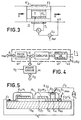
- a gas mixture G circulates in a pipe, passes through the enclosure 1 formed by the interior of the ion pump and leaves in the form of a gas mixture G 'with an oxygen concentration modified by the ion pump.
- an electrochemical measurement sensor S is placed at the output, measuring the concentration of the mixture at output G '.
- the electrical signals are transmitted to a comparator Co which receives on a second input a reference value Ref so as to act on the control voltage Vo and by the same fact on the current i, in amplitude and in polatire.
- the invention proposes a sensor comprising two electrochemical cells.
- the first cell detecting the stoichiometry of a small volume of gas mixture which is transmitted to it after catalysis, this small volume of gas mixture coming from a "test sample”.
- the second cell is an ion pump and modifies the composition of the gas mixture admitted inside the sensor so that the output signal V E1 / E2 of the measurement cell has a tilting for a value different from the stoichiometry of the gas mixture as it actually appears at the sensor inlet (Mex).
- Figure 4 schematically illustrates the operation of a sensor according to the invention.
- the three functions common to the sensors of the known art for example the sensor described in relation to FIG. 1: "test sample” 41, "catalysis” 42 and “measurement cell” 43 , these functions being able to be entirely or partly carried out by a common body.
- the composition of the gas mixture G ′ after test portion in the known art, being identical to or very close to the composition of the gas mixture in the external environment Mex where the mixture to be measured circulates. Before measurement, the gas mixture G "checks the relation (4).
- the ion pumping cell 44 using a control voltage V c , makes it possible to continuously modify the composition of the admitted gas mixture G 'by injecting or removing oxygen.
- test portion function can be carried out in different ways: using a calibrated orifice, an inert porous body or, in the case of sensors analogous to that of FIG. 1, using the catalyst body itself Ci extending the measuring electrode E 2.
- these functions correspond to regions of the sensor which cannot in general be distinguished in such a way clear, a single organ can perform all or part of these functions by itself.
- Ion pumping can be carried out at any point between the measurement cell and the test sample area, that is to say most often in the catalysis zone.
- This latter structure is particularly advantageous since it simultaneously allows good measurement sensitivity and a small quantity of gas admitted: of the order of mm 3 / s for example between 0.5 and 5 mm 3 / s; this in addition to the technological advantages due to the use of production techniques in thin or thick layers. It is therefore possible to significantly modify the oxygen composition of the admitted mixture G 'inside the sensor without requiring a large ion current within the solid electrolyte of the ion pumping cell, that is to say of the voltage of control V o or what amounts to the same of current i.
- FIG. 5 illustrates in section a first alternative embodiment of sensors according to the invention, according to a first approach.
- an additional electrochemical cell is integrated in the sensor and comprises a solid electrolyte E 12 inserted between two electrodes E 3 and E4.
- the second electrode E4 is merged with the extension of the measurement electrode E 2 .
- the assembly filling a channel pierced in the insulating envelope.
- the cell is exposed on the surface of the insulator S 1 so as to communicate with an oxygen-containing medium, this medium possibly being the Mex medium in which the gas mixture to be analyzed circulates G.
- the cell E 3 E 12 -E 4 is supplied by a control current i via the connections C 3 and C 4 , C 4 being merged with C 2 .
- FIG. 6 represents a practical embodiment in which the electrolyte E 12 is in the form of a layer or a plate attached or deposited on the extension of the measurement electrode. Then the enamel coating is deposited. The opening revealing the electrolyte E, 2 can be produced by masking and the electrode E 3 is then deposited. This electrode can be produced using a platinum lacquer.
- the electrolyte can easily be placed at the end of the substrate near the test sample area P es as illustrated in FIG. 7. This arrangement avoids providing an orifice in the enamel layer S,.
- the electrolyte can also be arranged in the form of a screen-printed layer as illustrated in FIG. 8.
- FIG. 10 more specifically illustrates the case where the electrolyte is deposited by screen printing as in the case of FIG. 8.
- the electrode e4 was merged with the extension of the measurement electrode. According to a second approach, three variants of which are illustrated in relation to the figures 11 to 13, the electrode E4 can be separate and the ion pumping cell E 2 -E 12 -E 4 appear as an element attached to the protective enamel. S 1 .
- the "test portion" area Pas is in the form of a calibrated orifice, similar to those used in certain types of sensors of the known art, limiting predetermined amount of gas mixture admitted to the interior of the sensor, that is to say in an enclosure underlying the ion pumping cell in which the composition of the gas mixture is modified and becomes G ′, this due to the action of this cell.
- This enclosure can be produced at the time of manufacture by masking and depositing the enamel layer or by any other process.
- the cell E 3 -E 12 -E 4 is then added to the assembly.
- the cell E 3 -E 12 -E 14 is also confused with the test sample area P es , in a manner analogous to the variants of FIGS. 9 and 10, of the first approach.
- test portion Pas is distinct from the cell E 3 -E 12 -E 4 and produced in a manner analogous to the variants illustrated by FIGS. 5 to 8.
- the ion pumping cell E 3 -E 12 -E 4 can be produced in a manner analogous to that of the measurement cell and have a generally planar structure instead to be in the form of a vertical stack: "electrode-electrolyte-electrode”.
- the etolyte E 12 is extended towards the outside by coming out of the protective enamel layer S 1 .
- the electrode E 3 defines a useful zone for exchange with the oxygen present in the external medium and serves as contact point C 3 .
- a cell produced according to this structure can also be adapted to the second approach.
- a second electrode is then deposited on the electrolyte, the assembly is deposited or attached to the insulating envelope, the second electrode being disposed on the communication channel with the catalysis zone of the measurement cell.
- the sensors according to the invention making it possible to offset the tilting of the response curve in "advance” or “delay” compared to the actual stoichiometry of the gaseous mixture circulating in the exhaust ducts, this continuously, are particularly interesting in the context of this application.
- FIG. 15 and 16 schematically illustrate the implementation of sensors of the invention in a system for regulating the richness of an air-fuel mixture admitted into the cylinders of a combustion engine.
- the engine 1 has an air intake A and fuel E which are mixed in a mixing member 5.
- This can be a tank carburetor, an injection device or any other similar device.
- the mixture is brought to engine 1 via line A / E.
- the member 5 is under the control of a regulating member 4.
- the link 12 is for example a mechanical coupling axis.
- the burnt gases are then ejected into the atmosphere AAb by an exhaust pipe E o .
- On the gas ejection path is arranged a sensor 2 in accordance with the invention which communicates with the exhaust gases G. In reality the sensor, as illustrated in FIG.
- the electrical signal output from the measurement cell V s is transmitted to a control device 3 by the electrical connections 10.
- the control device must be able to detect, for example using threshold logic, the tilting of the curve V E1 / E 2 and its output controls the regulating member 4 via the link 11.
- Figure 14 of this patent is shown a system comprising a single sensor detecting a predetermined value of the composition of the exhaust gas, value set at the time of manufacture.
- Figure 15 of this patent is shown a system comprising two sensors; number which can be increased. Each sensor detects a distinct value of the composition of the exhaust gases, values also fixed at the time of manufacture.
- the regulation system is supplemented by a computer 6, analog or digital, which receives from different sensors 7 or control members 7, via the links 14, information on parameters characteristic of the operation. engine, environment and various instructions. These parameters can be, by way of nonlimiting example, the outside temperature, the air flow rate or the engine speed: accelerated, idle, etc.
- the computer 6, generates with the aid of specialized organs the current i serving for the control of the ion pumping cell which is provided the sensor of invention 2, current transmitted by the electrical connections 13.
- the amplitude and polarity of the current i are used to determine the quantity of oxygen pumped, injected or extracted, to modify the composition of the test sample and thereby offset the tilting of the response curve of the sensor relative to the stoichiometry of the gas mixture circulating in the exhaust ducts E c .
- the air-fuel mixture admitted into the A / E line is modified accordingly.
- FIG. 16 illustrates three cases of operation of the regulation system of FIG. 15, this for a given temperature of the exhaust gases.
- the tipping points R " (lean mixture) and R B (rich mixture) correspond to shifts of the same amplitude but in opposite directions with respect to the stoichiometry. From the knowledge of the control current i, it can be determined when detects the tilting of the curve the richness of the air-fuel mixture admitted into the engine cylinders It should be remembered that this tilting corresponds to the stoichiometry of the mixture admitted into the sensor at the level of the measurement electrode.
- the relation between the control current i and the amplitude of the shift of the tilting of the curve compared to the true stoichiometry of the gas mixture at the input of the sensor can be determined by experience or by calculation, using in particular relations (6) and (7), knowing the quantity of fluid admitted into the sensor per unit of time ("test sample").
- test sample the quantity of fluid admitted into the sensor per unit of time
- the richness of the air-fuel mixture admitted into the cylinders can therefore be regulated around a continuously adjustable setpoint by acting on the amplitude and the polarity of the control current i which in turn determines the quantity of oxygen. "pumped".
- the computer 6 incorporates an adjustable or programmable current source in amplitude and polarity (not shown in FIG. 15).
- adjustable sources are known to those skilled in the art and do not require further description. The same is true of the exact conditions for developing the current i and of the variation curves of the richness of the mixture admitted as a result. These curves depend in particular on the type of motor used.
- this method is not limited to regulating the air-fuel mixture of an internal combustion engine.
- the motor 1 can be replaced, by way of nonlimiting example, by the burners of a boiler.
- the sensor 2 is then placed in the circuit E c for evacuating the burnt gases. It can be applied to any combustion effect device, the regulation for its part can be carried out in a non-automatic way by modifying the current i using a manual control member of the current source.
- An additional provision which can be adopted, to ensure a better functioning of the sensor of the invention consists in regulating the temperature of this sensor to a predetermined value.
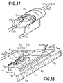
- FIG. 17 illustrates an exemplary embodiment of such a device.
- the sensor 2 of FIG. 15 is inserted into a tube 170, made of quartz for example.
- the assembly is surrounded by a resistive turn 173 supplied with the help of the connections 174 by an electric current.
- This current can be fixed once and for all to ensure an average temperature inside the tube or, on the contrary, be adjustable as a function of the temperature of the body of the sensor measured by a sensor 171, a thermocouple for example.
- the output signal from the thermocouple 171 is transmitted via the links 172 to a servo-control unit, not shown. Usually, this signal is compared with a reference value so as to adjust the current supplying the resistive heating coil 173 to a value compensating for the drifts in measured temperature.
- the device which has just been described adapts to the sensors produced according to all the variants previously described and can be implemented within the framework of the regulation system described in relation to FIGS. 15 and 16.
- the invention proposes a sensor structure making it possible to obviate this drawback.
- FIG. 18 A first embodiment of a sensor according to this approach is illustrated in FIG. 18 in partial view, in which cuts have been made to highlight the hidden parts of the sensor.
- several pumping cells are integrated into the sensor.
- these cells have a common electrolyte E 12 and a common electrode E4 which is the extension of the measurement electrode of the measurement cell in an identical manner to the structures previously described.
- the structure of the sensor in FIG. 18 is similar overall to that of the sensor described in relation to FIG. 5 and the constituent elements which are not necessary for understanding the present approach will no longer be described.
- Individual ion pumping cells are defined by the regions underlying the electrodes E 31 to E34, which are exposed on the surface of the insulator Si and on which electrical contacts have been established with the electrical connections C 31 to C 33 . More generally, the cells which are represented in FIG. 18 four in number can be of any number n.
- each of the electrodes can be traversed by an elementary current which can take the values, o, + ⁇ i or -Ai
- the equivalent control current i can take any discrete value between o and nAi, in absolute value.
- the amplitude of the shift of the tilting of the response curve of the measuring cell on either side of the stoichiometry of the gas mixture at the input of the sensor may take as many discrete values as the number of ion pumping cells with which the sensor is provided.
- the electrode E4 remains common to all the cells, but the solid electrolyte is divided into elementary tongues E 121 to E 124 deposited on the electrode E4 which is the extension of the measurement electrode E 2 / P 2 and protrude laterally , for example alternately on the two edges of the substrate S b . Electrodes E 31 to E 33 are deposited on the periphery and provide electrical contact with the connections C 3 , to C 34 .
- control of the ion pumping cells can be carried out in voltage or in current. In the latter case, it suffices to have a set of n elementary bipolar current sources, operating all or nothing under the control of signals delivered by the computer 6.
- the first is to regulate the operating temperature of the sensor. To do this, the device described in relation to FIG. 17 can be implemented.
- FIG. 20 schematically illustrates a circuit for controlling the voltage of the elementary ion pumping cells of a sensor produced according to the fourth approach, this in relation to the regulation system of FIG. 15.
- the computer 6 comprises a calculating member 60 developing a control word N for example in pure binary code transmitted to a decoding and interface circuit 61 which provides on the outputs S 1 to S 5 five control signals of binary type actuating each a switch, respectively 62 to 66.
- the switch 66 is intended to activate a positive + V c : 67 or negative -V c : 68 control voltage source, depending on the direction of the desired offset.
- the number of switches 62 to 65 closed determines the magnitude of the offset.
- These switches are each connected to one of the electrodes E 31 to E34 defining the elementary ion pumping cells.
- the common electrode E4 is connected to the link C 4 at the point common to the two sources 67 and 68.
- two ion pumping cells can be used to obtain the currents + Ai and - ⁇ i.
- each elementary cell must have a separate pair of electrodes: respectively To do this, the structures described in relation to FIGS. 11 to 14 will be used. If the electrodes E 41 and E 32 are connected to a potential + V c supplied by the control source, this by means of switches not shown, and the electrodes E 31 and E 42 at an OV potential, it follows that the two elementary cells can be crossed by currents -Ai and + Ai respectively, causing an offset of the tipping point of the response curve of the measuring cell not shown in FIG. 21, of the same amplitude but in the opposite direction. More generally the number of cells is equal to 2n
- this variant also adapts to the case where the two ion pumping cells are controlled analogically by a current or a voltage of variable amplitude, but of single polarity.
- the sensors produced according to the thin or thick film technique may be preferred for certain applications, since they have less inertia of response, less bulk and can be made according to the technology usually used in microelectronics. According to this last aspect, they can in particular be intimately associated with other electronic components produced on the same substrate or on a neighboring substrate, protected from high temperatures so that the electronic circuits can function properly.
- the connections C, / C 2 also produced by deposition, can be connected to a threshold amplifier intended to detect the tilting of the curves in FIG. 2. This aspect is outside the scope of the invention.
- Other advantages have been recalled in the aforementioned European patent applications.
Landscapes
- Chemical & Material Sciences (AREA)
- Life Sciences & Earth Sciences (AREA)
- Health & Medical Sciences (AREA)
- Biochemistry (AREA)
- Chemical Kinetics & Catalysis (AREA)
- Electrochemistry (AREA)
- Physics & Mathematics (AREA)
- Analytical Chemistry (AREA)
- Molecular Biology (AREA)
- General Health & Medical Sciences (AREA)
- General Physics & Mathematics (AREA)
- Immunology (AREA)
- Pathology (AREA)
- Measuring Oxygen Concentration In Cells (AREA)
- Combined Controls Of Internal Combustion Engines (AREA)
- Electrical Control Of Air Or Fuel Supplied To Internal-Combustion Engine (AREA)
Claims (17)
Priority Applications (1)
| Application Number | Priority Date | Filing Date | Title |
|---|---|---|---|
| AT81401648T ATE13596T1 (de) | 1980-11-17 | 1981-10-20 | Elektrochemischer messfuehler zum bestimmen der gaskonzentration in einem gemisch und regelungsvorrichtung fuer das luft-brennstoffverh|ltnis mit diesem messfuehler. |
Applications Claiming Priority (2)
| Application Number | Priority Date | Filing Date | Title |
|---|---|---|---|
| FR8024380A FR2494445A1 (fr) | 1980-11-17 | 1980-11-17 | Capteur electrochimique des concentrations d'especes dans un melange fluide et systeme de regulation de la richesse d'un melange air-carburant mettant en oeuvre un tel capteur |
| FR8024380 | 1980-11-17 |
Publications (3)
| Publication Number | Publication Date |
|---|---|
| EP0052542A1 EP0052542A1 (de) | 1982-05-26 |
| EP0052542B1 true EP0052542B1 (de) | 1985-05-29 |
| EP0052542B2 EP0052542B2 (de) | 1991-03-06 |
Family
ID=9248043
Family Applications (1)
| Application Number | Title | Priority Date | Filing Date |
|---|---|---|---|
| EP81401648A Expired - Lifetime EP0052542B2 (de) | 1980-11-17 | 1981-10-20 | Elektrochemischer Messfühler zum Bestimmen der Gaskonzentration in einem Gemisch und Regelungsvorrichtung für das Luft-Brennstoff-Verhältnis mit diesem Messfühler |
Country Status (8)
| Country | Link |
|---|---|
| US (1) | US4741817A (de) |
| EP (1) | EP0052542B2 (de) |
| JP (2) | JPS57111441A (de) |
| AT (1) | ATE13596T1 (de) |
| CA (1) | CA1193340A (de) |
| DE (1) | DE3170750D1 (de) |
| ES (1) | ES8301027A1 (de) |
| FR (1) | FR2494445A1 (de) |
Families Citing this family (37)
| Publication number | Priority date | Publication date | Assignee | Title |
|---|---|---|---|---|
| FR2494445A1 (fr) * | 1980-11-17 | 1982-05-21 | Socapex | Capteur electrochimique des concentrations d'especes dans un melange fluide et systeme de regulation de la richesse d'un melange air-carburant mettant en oeuvre un tel capteur |
| US4389881A (en) * | 1981-07-31 | 1983-06-28 | Ford Motor Company | Method of measuring an air to fuel ratio |
| JPS59178354A (ja) * | 1983-03-29 | 1984-10-09 | Ngk Spark Plug Co Ltd | 酸素センサ |
| JPH0715452B2 (ja) * | 1983-10-05 | 1995-02-22 | 株式会社日立製作所 | 空燃比検出器 |
| JPS6086457A (ja) * | 1983-10-19 | 1985-05-16 | Hitachi Ltd | エンジン制御用空燃比センサ |
| EP0147989A3 (de) * | 1983-12-17 | 1985-08-14 | NGK Spark Plug Co. Ltd. | Messfühler zum Messen des Luft-Kraftstoff-Verhältnisses |
| JPS60135756A (ja) * | 1983-12-24 | 1985-07-19 | Ngk Insulators Ltd | 電気化学的セルの製造方法 |
| AT396998B (de) * | 1985-12-09 | 1994-01-25 | Ottosensors Corp | Messeinrichtungen und rohranschluss sowie verfahren zur herstellung einer messeinrichtung und verfahren zur verbindung von rohren mit einer messeinrichtung bzw. zur herstellung von rohranschlüssen |
| JP2797306B2 (ja) * | 1987-03-13 | 1998-09-17 | 三菱自動車工業株式会社 | 酸素センサ及び該センサを適用した内燃エンジンの空燃比制御装置 |
| FR2620868B1 (fr) * | 1987-09-22 | 1994-03-25 | Thomson Csf | Procede de realisation de microcavites et application a un capteur electrochimique ainsi qu'a un chomatographe en phase gazeuse |
| FR2621126B1 (fr) * | 1987-09-25 | 1994-04-15 | Thomson Csf | Capteur electrochimique, a structure integree, de mesure de concentrations relatives d'especes reactives |
| GB9004549D0 (en) * | 1990-03-01 | 1990-04-25 | Ici Plc | Heat machines |
| US5250169A (en) * | 1991-06-07 | 1993-10-05 | Ford Motor Company | Apparatus for sensing hydrocarbons and carbon monoxide |
| US5139958A (en) * | 1991-09-24 | 1992-08-18 | The United States Of America As Represented By The United States Department Of Energy | Method and device for the determination of low concentrations of oxygen in carbonaceous materials |
| US5360528A (en) * | 1992-07-20 | 1994-11-01 | General Motors Corporation | Wide range oxygen sensor |
| DE4243733C2 (de) * | 1992-12-23 | 2003-03-27 | Bosch Gmbh Robert | Sensor zur Bestimmung von Gaskomponenten und/oder Gaskonzentrationen von Gasgemischen |
| DE4308767A1 (de) * | 1993-03-19 | 1994-09-22 | Bosch Gmbh Robert | Verfahren zur Bestimmung von Gaskomponenten und/oder Gaskonzentrationen von Gasgemischen |
| DE4333230B4 (de) * | 1993-09-30 | 2004-03-25 | Robert Bosch Gmbh | Elektrochemischer Meßfühler zur Bestimmung des Sauerstoffgehalts in Gasen |
| US5827415A (en) * | 1994-09-26 | 1998-10-27 | The Board Of Trustees Of Leland Stanford Jun. Univ. | Oxygen sensor |
| DE19901957C2 (de) * | 1999-01-20 | 2003-04-17 | Bosch Gmbh Robert | Sensor zur Analyse von Gasen |
| JP2002174620A (ja) * | 2000-12-07 | 2002-06-21 | Denso Corp | ガスセンサ素子及びガスセンサ |
| DE10160720A1 (de) | 2001-12-11 | 2003-06-18 | Basf Ag | Kosmetisches Mittel enthaltend wenigstens ein Copolymer mit N-Vinyllactameinheiten |
| JP4077365B2 (ja) * | 2003-05-23 | 2008-04-16 | 株式会社日立製作所 | 酸素濃度検出素子 |
| FR2879342B1 (fr) * | 2004-12-15 | 2008-09-26 | Thales Sa | Cathode a emission de champ, a commande optique |
| EP2343507B1 (de) * | 2009-12-24 | 2012-11-28 | EM Microelectronic-Marin SA | Verfahren zum kapazitiven Messen eines physikalischen Parameters und elektronischer Schnittstellenschaltkreis für einen kapazitiven Sensor |
| JP5126388B2 (ja) | 2010-08-19 | 2013-01-23 | 株式会社デンソー | ガスセンサ制御装置 |
| JP5884701B2 (ja) | 2012-02-01 | 2016-03-15 | 株式会社デンソー | 内燃機関の排出ガス浄化装置 |
| JP5884702B2 (ja) | 2012-02-01 | 2016-03-15 | 株式会社デンソー | 内燃機関の排出ガス浄化装置 |
| JP5867357B2 (ja) * | 2012-02-03 | 2016-02-24 | 株式会社デンソー | 内燃機関の排出ガス浄化装置 |
| JP5748180B2 (ja) | 2012-02-10 | 2015-07-15 | 株式会社デンソー | 触媒の劣化診断装置 |
| JP5817581B2 (ja) | 2012-02-17 | 2015-11-18 | 株式会社デンソー | 内燃機関の排出ガス浄化装置 |
| KR101460500B1 (ko) * | 2013-02-27 | 2014-11-11 | 한양대학교 에리카산학협력단 | 칼코지나이드계 나노선을 이용한 열화학 가스 센서 및 그 제조방법 |
| JP6237057B2 (ja) | 2013-09-27 | 2017-11-29 | 株式会社デンソー | ガスセンサ制御装置 |
| JP6403985B2 (ja) | 2014-05-02 | 2018-10-10 | ローム株式会社 | 限界電流式ガスセンサおよびその製造方法、およびセンサネットワークシステム |
| JP6517686B2 (ja) * | 2015-02-16 | 2019-05-22 | 日本特殊陶業株式会社 | ガスセンサ |
| WO2017070652A1 (en) * | 2015-10-23 | 2017-04-27 | Boston Scientific Scimed, Inc. | Endoscopic submucosal dissection hood |
| CN115411308B (zh) * | 2021-05-27 | 2025-09-23 | 未势能源科技有限公司 | 燃料电池系统及其空气流量控制方法、车辆 |
Family Cites Families (24)
| Publication number | Priority date | Publication date | Assignee | Title |
|---|---|---|---|---|
| US3981785A (en) * | 1969-07-18 | 1976-09-21 | Westinghouse Electric Corporation | Electrochemical sensor for reactive gas mixtures |
| US3768259A (en) * | 1971-07-06 | 1973-10-30 | Universal Oil Prod Co | Control for an engine system |
| NL7304299A (de) * | 1973-03-28 | 1974-10-01 | ||
| US3909384A (en) * | 1973-06-18 | 1975-09-30 | Texas Instruments Inc | Electro-chemical sensors for trace gases |
| NL7309537A (nl) * | 1973-07-09 | 1975-01-13 | Philips Nv | Gasanalyse-apparaat. |
| DE2460066C3 (de) * | 1974-12-19 | 1981-08-06 | Brown, Boveri & Cie Ag, 6800 Mannheim | Verfahren und Vorrichtung zum selbsttätigen Regeln des Brenstoff-Luftverhältnisses einer Verbrennung |
| US4158166A (en) * | 1976-11-24 | 1979-06-12 | Westinghouse Electric Corp. | Combustibles analyzer |
| DE2718907C2 (de) * | 1977-04-28 | 1984-04-12 | Robert Bosch Gmbh, 7000 Stuttgart | Meßfühler zur Bestimmung des Sauerstoffgehalts in Abgasen |
| US4226692A (en) * | 1978-05-22 | 1980-10-07 | Isenberg Arnold O | Solid state combustion sensor |
| JPS5562349A (en) * | 1978-11-02 | 1980-05-10 | Nissan Motor Co Ltd | Measuring method for air fuel ratio |
| FR2441164A1 (fr) * | 1978-11-07 | 1980-06-06 | Thomson Csf | Capteur electrochimique des concentrations relatives d'especes reactives dans un melange fluide |
| FR2442444A1 (fr) * | 1978-11-21 | 1980-06-20 | Thomson Csf | Capteur electrochimique des concentrations relatives d'especes reactives dans un melange fluide, et systeme comportant un tel capteur, notamment pour la regulation |
| FR2444272A1 (fr) * | 1978-12-12 | 1980-07-11 | Thomson Csf | Capteur electrochimique des concentrations d'especes dans un melange fluide du type a electrode de reference interne de pression partielle |
| DE2909201C2 (de) * | 1979-03-09 | 1986-11-20 | Robert Bosch Gmbh, 7000 Stuttgart | Elektrochemischer Meßfühler für die Bestimmung des Sauerstoffgehaltes in Gasen, insbesondere in Abgasen von Brennkraftmaschninen |
| JPS55154450A (en) * | 1979-05-19 | 1980-12-02 | Nissan Motor Co Ltd | Air-fuel-ratio detector |
| JPS55156855A (en) * | 1979-05-25 | 1980-12-06 | Nissan Motor Co Ltd | Air fuel ratio measuring device |
| DE2923483A1 (de) * | 1979-06-09 | 1980-12-11 | Bosch Gmbh Robert | Polarographischer messfuehler fuer die bestimmung des sauerstoffgehaltes in gasen, insbesondere in abgasen von verbrennungsmotoren |
| JPS562548A (en) * | 1979-06-22 | 1981-01-12 | Nissan Motor Co Ltd | Controller for air fuel ratio of internal combustion engine |
| JPS6029065B2 (ja) * | 1979-07-28 | 1985-07-08 | 日産自動車株式会社 | 空燃比制御信号発生装置 |
| JPS6029066B2 (ja) * | 1979-07-28 | 1985-07-08 | 日産自動車株式会社 | 空燃比制御信号発生装置 |
| NL7906833A (nl) * | 1979-09-13 | 1981-03-17 | Philips Nv | Gasanalyseapparaat. |
| US4248941A (en) * | 1979-12-26 | 1981-02-03 | United Tecnologies Corporation | Solid electrolyte electrochemical cell |
| US4272329A (en) * | 1980-03-03 | 1981-06-09 | Ford Motor Company | Steady state mode oxygen sensor and method |
| FR2494445A1 (fr) * | 1980-11-17 | 1982-05-21 | Socapex | Capteur electrochimique des concentrations d'especes dans un melange fluide et systeme de regulation de la richesse d'un melange air-carburant mettant en oeuvre un tel capteur |
-
1980
- 1980-11-17 FR FR8024380A patent/FR2494445A1/fr active Granted
-
1981
- 1981-10-20 EP EP81401648A patent/EP0052542B2/de not_active Expired - Lifetime
- 1981-10-20 AT AT81401648T patent/ATE13596T1/de not_active IP Right Cessation
- 1981-10-20 DE DE8181401648T patent/DE3170750D1/de not_active Expired
- 1981-11-13 CA CA000390021A patent/CA1193340A/en not_active Expired
- 1981-11-16 JP JP56183612A patent/JPS57111441A/ja active Granted
- 1981-11-16 ES ES507162A patent/ES8301027A1/es not_active Expired
-
1985
- 1985-03-28 US US06/716,618 patent/US4741817A/en not_active Expired - Fee Related
-
1991
- 1991-11-28 JP JP3314985A patent/JPH0820414B2/ja not_active Expired - Lifetime
Also Published As
| Publication number | Publication date |
|---|---|
| JPH0211863B2 (de) | 1990-03-16 |
| DE3170750D1 (en) | 1985-07-04 |
| ES507162A0 (es) | 1982-11-01 |
| US4741817A (en) | 1988-05-03 |
| FR2494445A1 (fr) | 1982-05-21 |
| ES8301027A1 (es) | 1982-11-01 |
| JPS57111441A (en) | 1982-07-10 |
| CA1193340A (en) | 1985-09-10 |
| EP0052542B2 (de) | 1991-03-06 |
| EP0052542A1 (de) | 1982-05-26 |
| JPH055721A (ja) | 1993-01-14 |
| JPH0820414B2 (ja) | 1996-03-04 |
| ATE13596T1 (de) | 1985-06-15 |
| FR2494445B1 (de) | 1984-06-22 |
Similar Documents
| Publication | Publication Date | Title |
|---|---|---|
| EP0052542B1 (de) | Elektrochemischer Messfühler zum Bestimmen der Gaskonzentration in einem Gemisch und Regelungsvorrichtung für das Luft-Brennstoff-Verhältnis mit diesem Messfühler | |
| EP0012647B1 (de) | Elektrochemischer Sensor zur Messung der Konzentrationen der Komponenten eines Flüssigkeitsgemisches mit einer Referenzelektrode zur Feststellung des Partialdrucks | |
| FR2462707A1 (fr) | Dispositif de production d'un signal pour le reglage par reaction du rapport d'un melange air/carburant | |
| EP0011530B1 (de) | Elektrochemischer Messfühler zur Bestimmung der relativen Konzentrationen von reaktiven Substanzen in einer fluiden Mischung, Verfahren zur Herstellung des Messfühlers und einen solchen Messfühler enthaltendes System, insbesondere für Regelzwecke | |
| FR2636737A1 (fr) | Capteur de type resistif, de mesure de concentrations relatives d'especes reactives fluides, compense en temperature | |
| EP0990144B1 (de) | Integrierter keramischer abgassensor | |
| FR2489887A1 (fr) | Systeme pour le reglage par contre-reaction du rapport air/carburant dans un moteur a combustion interne, avec un moyen pour controler le courant fourni a un capteur d'oxygene | |
| FR2459885A1 (fr) | Systeme pour une commande a retro-action du rapport air/carburant dans un moteur a combustion interne | |
| FR2462706A1 (fr) | Dispositif de production d'un signal pour le reglage par reaction du rapport d'un melange air/carburant | |
| FR2472749A1 (fr) | Procede de production d'un element detectant l'oxygene en electrolyte solide de structure feuilletee du type a cellule de concentration | |
| EP0309334B1 (de) | Verfahren zur Herstellung von Mikrohohlräumen und Anwendung für einen elektrochemischen Sensor und für einen Gaschromatografen | |
| FR2467297A1 (fr) | Systeme de controle, par contre-reaction, du rapport air/carburant dans un moteur a combustion interne avec sous-systeme pour controler l'alimentation en courant vers un capteur d'oxygene | |
| FR2467988A1 (fr) | Systeme de controle, par contre-reaction, du rapport air/carburant dans un moteur a combustion interne, avec un moyen pour controler l'alimentation en courant vers un capteur d'oxygene | |
| EP0597078B1 (de) | Vorrichtung zum selektiven nachweis von gasen | |
| FR2817966A1 (fr) | Detecteur de gaz multicouches et systeme associe de detection de concentration de gaz | |
| FR2744220A1 (fr) | Dispositif de detection de la concentration en oxygene et son procede de fabrication | |
| FR2466624A1 (fr) | Systeme de reglage par contre-reaction, du rapport air/carburant d'un moteur a combustion interne ayant un moyen pour alimenter un capteur d'oxygene en courant regle | |
| EP0309360B1 (de) | Elektrochemische Zelle, mit integrierter Struktur, zur Messung der relativen Konzentrationen von reaktiven Stoffen | |
| FR2488692A1 (fr) | Procede de production d'un element captant l'oxygene a electrolyte solide de structure feuilletee avec electrode externe deposee en phase vapeur | |
| EP0011038B1 (de) | Elektrochemischer Messfühler der relativen Konzentrationen von reagierenden Materien in einer flüssigen Mischung und System mit einem solchen Messfühler, insbesondere für die Regelung | |
| FR2864147A1 (fr) | Dispositif de sonde pour des gaz d'echappement d'un moteur a combustion interne et procede de fonctionnement et d'exploitation | |
| EP0018871B1 (de) | Vorrichtung zum Messen der Kohlenmonoxidkonzentration in Abgasen, Verfahren zu ihrer Herstellung und die Vorrichtung enthaltendes Regelsystem | |
| FR2479471A1 (fr) | Jauges a oxygene a reference interne et a electrolyte solide | |
| FR2829839A1 (fr) | Element de capteur pour un capteur de gaz a electrolyte solide | |
| EP0154099B1 (de) | Detektionsverfahren für ionisierbare Bestandteile wie etwa Sauerstoff |
Legal Events
| Date | Code | Title | Description |
|---|---|---|---|
| PUAI | Public reference made under article 153(3) epc to a published international application that has entered the european phase |
Free format text: ORIGINAL CODE: 0009012 |
|
| AK | Designated contracting states |
Designated state(s): AT CH DE GB IT NL SE |
|
| 17P | Request for examination filed |
Effective date: 19820611 |
|
| ITF | It: translation for a ep patent filed | ||
| GRAA | (expected) grant |
Free format text: ORIGINAL CODE: 0009210 |
|
| AK | Designated contracting states |
Designated state(s): AT CH DE GB IT LI NL SE |
|
| REF | Corresponds to: |
Ref document number: 13596 Country of ref document: AT Date of ref document: 19850615 Kind code of ref document: T |
|
| REF | Corresponds to: |
Ref document number: 3170750 Country of ref document: DE Date of ref document: 19850704 |
|
| PLBI | Opposition filed |
Free format text: ORIGINAL CODE: 0009260 |
|
| 26 | Opposition filed |
Opponent name: NGK SPARK PLUG CO., LTD. Effective date: 19860228 |
|
| NLR1 | Nl: opposition has been filed with the epo |
Opponent name: NGK SPARK PLUG CO., LTD. |
|
| RAP4 | Party data changed (patent owner data changed or rights of a patent transferred) |
Owner name: THOMSON-CSF |
|
| PUAH | Patent maintained in amended form |
Free format text: ORIGINAL CODE: 0009272 |
|
| STAA | Information on the status of an ep patent application or granted ep patent |
Free format text: STATUS: PATENT MAINTAINED AS AMENDED |
|
| 27A | Patent maintained in amended form |
Effective date: 19910306 |
|
| AK | Designated contracting states |
Kind code of ref document: B2 Designated state(s): AT CH DE GB IT LI NL SE |
|
| ITF | It: translation for a ep patent filed | ||
| REG | Reference to a national code |
Ref country code: CH Ref legal event code: AEN |
|
| NLR2 | Nl: decision of opposition | ||
| NLR3 | Nl: receipt of modified translations in the netherlands language after an opposition procedure | ||
| PGFP | Annual fee paid to national office [announced via postgrant information from national office to epo] |
Ref country code: CH Payment date: 19930913 Year of fee payment: 13 |
|
| PGFP | Annual fee paid to national office [announced via postgrant information from national office to epo] |
Ref country code: SE Payment date: 19930920 Year of fee payment: 13 |
|
| PGFP | Annual fee paid to national office [announced via postgrant information from national office to epo] |
Ref country code: AT Payment date: 19931029 Year of fee payment: 13 |
|
| ITTA | It: last paid annual fee | ||
| PGFP | Annual fee paid to national office [announced via postgrant information from national office to epo] |
Ref country code: NL Payment date: 19931031 Year of fee payment: 13 |
|
| PG25 | Lapsed in a contracting state [announced via postgrant information from national office to epo] |
Ref country code: AT Effective date: 19941020 |
|
| PG25 | Lapsed in a contracting state [announced via postgrant information from national office to epo] |
Ref country code: SE Effective date: 19941021 |
|
| PG25 | Lapsed in a contracting state [announced via postgrant information from national office to epo] |
Ref country code: LI Effective date: 19941031 Ref country code: CH Effective date: 19941031 |
|
| EAL | Se: european patent in force in sweden |
Ref document number: 81401648.1 |
|
| PG25 | Lapsed in a contracting state [announced via postgrant information from national office to epo] |
Ref country code: NL Effective date: 19950501 |
|
| NLV4 | Nl: lapsed or anulled due to non-payment of the annual fee | ||
| REG | Reference to a national code |
Ref country code: CH Ref legal event code: PL |
|
| EUG | Se: european patent has lapsed |
Ref document number: 81401648.1 |
|
| PGFP | Annual fee paid to national office [announced via postgrant information from national office to epo] |
Ref country code: GB Payment date: 19960918 Year of fee payment: 16 |
|
| PGFP | Annual fee paid to national office [announced via postgrant information from national office to epo] |
Ref country code: DE Payment date: 19960919 Year of fee payment: 16 |
|
| PG25 | Lapsed in a contracting state [announced via postgrant information from national office to epo] |
Ref country code: GB Free format text: LAPSE BECAUSE OF NON-PAYMENT OF DUE FEES Effective date: 19971020 |
|
| GBPC | Gb: european patent ceased through non-payment of renewal fee |
Effective date: 19971020 |
|
| PG25 | Lapsed in a contracting state [announced via postgrant information from national office to epo] |
Ref country code: DE Free format text: LAPSE BECAUSE OF NON-PAYMENT OF DUE FEES Effective date: 19980701 |
|
| APAH | Appeal reference modified |
Free format text: ORIGINAL CODE: EPIDOSCREFNO |