EP0052966B1 - Système d'amarrage pour avion - Google Patents
Système d'amarrage pour avion Download PDFInfo
- Publication number
- EP0052966B1 EP0052966B1 EP81305228A EP81305228A EP0052966B1 EP 0052966 B1 EP0052966 B1 EP 0052966B1 EP 81305228 A EP81305228 A EP 81305228A EP 81305228 A EP81305228 A EP 81305228A EP 0052966 B1 EP0052966 B1 EP 0052966B1
- Authority
- EP
- European Patent Office
- Prior art keywords
- elements
- further characterised
- apertures
- grid
- rails
- Prior art date
- Legal status (The legal status is an assumption and is not a legal conclusion. Google has not performed a legal analysis and makes no representation as to the accuracy of the status listed.)
- Expired
Links
Images


Classifications
-
- B—PERFORMING OPERATIONS; TRANSPORTING
- B64—AIRCRAFT; AVIATION; COSMONAUTICS
- B64F—GROUND OR AIRCRAFT-CARRIER-DECK INSTALLATIONS SPECIALLY ADAPTED FOR USE IN CONNECTION WITH AIRCRAFT; DESIGNING, MANUFACTURING, ASSEMBLING, CLEANING, MAINTAINING OR REPAIRING AIRCRAFT, NOT OTHERWISE PROVIDED FOR; HANDLING, TRANSPORTING, TESTING OR INSPECTING AIRCRAFT COMPONENTS, NOT OTHERWISE PROVIDED FOR
- B64F1/00—Ground or aircraft-carrier-deck installations
- B64F1/12—Ground or aircraft-carrier-deck installations for anchoring aircraft
- B64F1/125—Mooring or ground handling devices for helicopters
Definitions
- This invention relates to mooring devices, for aircraft and is particularly concerned with such a device incorporating a grid for use in securing an aircraft such as a helicopter on the deck of a ship.
- a device of this latter type is exemplified by FR-A-2,180,499 (GB - A-1,401,387) and has a grid that comprises a circular apertured surface having an external diameter of about 2.5 m (eight feet) and which is manufactured by machining from a sheet of stainless steel.
- FR-A-2,180,499 GB - A-1,401,387
- a grid that comprises a circular apertured surface having an external diameter of about 2.5 m (eight feet) and which is manufactured by machining from a sheet of stainless steel.
- the invention provides a mooring device comprising a grid adapted for engagement by a harpoon carried by an aircraft such as a helicopter, characterised in that the grid comprises a plurality of individual substantially identical separate elements and retaining means securing said element in juxtaposed relationship providing a plurality of apertures for engagement by said harpoon.
- the elements are generally rectangular in plan and are arranged in parallel rows.
- Each element preferably has a central region having a plurality of apertures of a desired shape, and an edge region having a plurality of half apertures arranged so that when the element is secured in juxtaposed relationship to another like element by said retaining means, the half apertures of the respective elements combine to form apertures corresponding in shape to the apertures of the central region.
- the retaining means may comprise a plurality of parallel rails for attachment in parallel relationship to a surface on which the grid is to be installed, the rails being shaped for engagement by downwardly depending leg portions formed on the elements.
- the rails are formed as co-operating pairs and are shaped so that each co-operating pair defines therebetween a slot of inverted T-shape in cross-section, the centre of the slot being aligned with the adjacent longitudinal edges of two adjacent rows of elements.
- the leg portions of each element desirably have inwardly directed lip portions that co-operate in side-by-side arrangement to locate said elements in the T-shaped slot.
- the slots are open-ended whereby said elements can be slid into position along the rails.
- the said retaining means may include lateral closing beams for attachment to a surface on which the grid is installed.
- Interlocking means may be provided on each element and may comprise a male lug located along one of the longitudinal and lateral sides of each element and complementary channels located along the other of the longitudinal and lateral sides whereby, when the elements are placed in juxtaposed relationship, the lugs of one element locate in the channels of adjacent elements.
- a mooring device embodying the invention and including a grid assembly 20 is shown installed on a deck surface 21 of a ship.
- the grid assembly 20 comprises a plurality of individual identical separate elements 22 of generally rectangular outline plan-form shape.
- the elements 22 are arranged in juxtaposed relationship in parallel rows to provide a grid having an upper surface consisting of a plurality of adjacent apertures 23 for engagement by a harpoon member carried by an aircraft such as a helicopter (not shown).
- the grid assembly 20 itself has a rectangular plan-form shape, and parallel slotted tracks 24 extend along longitudinal edges thereof for engagement by other apparatus such as an aircraft deck handling trolley.
- Inclined ramp surfaces 25 surround the grid assembly 20 to enable the grid to be traversed by a wheeled aircraft undercarriage.
- Figure 2 is a fragmentary plan of part of the grid assembly 20 on an enlarged scale, one of the elements being delineated by broken outline 22a - for explanatory purposes.
- Each of the elements 22 is rectangular in plan-form and is manufactured as an investment casting subsequently treated by bead blasting to improve surface finish and hardness.
- Each of the elements 22 measures 300 mm x 175 mm and is provided in a central region of its upper surface with two circular apertures 26 and, around its edges, with eight semi-circular apertures 26a. Thus, when located in juxtaposed relationship, the elements 22 provide a grid surface comprised of a plurality of identical circular apertures.
- Adjacent rows of apertures 26 are offset and an upper surface around each aperture 26 is shaped so as to define generally hexagonal boundary lines 27 around each hole to provide a honeycomb effect.
- the elements 22 are retained on the deck surface by pairs of parallel, longitudinally extending rails 28 which are equi-spaced laterally on either side of the longitudinal boundaries of element 22.
- each of the rails 28 has an inwardly extending flange so that, as a pair, the rails 28 define parallel longitudinally extending slots 29 of inverted T-shape in cross-section.
- the elements 22 are provided with integral downwardly projecting leg portions 30 which, in the vicinity of the longitudinal boundaries, are machined to form an inwardly extending lipped portion 31 to engage, respectively, the flanged rails 28.
- adjacent elements 22 are located in a common slot 29.
- the slots 29 are open-ended so that respective elements 22 can be slid into position along the rails 28 when assembling the grid on the deck 21.
- a vertical boundary surface of the legs 30 located along one of the longitudinal boundaries of the element 22 are provided with male lug 32 and those along the opposite longitudinal boundary of an adjacent element 22 are provided with co-operating female channels 33.
- a similar lug 32 and channel 33 are provided respectively along the lateral boundaries of each element 22 thereby providing interlocking of respective elements 22 when arranged in juxtaposed relationship.
- the longitudinal boundaries of the grid 20 comprise retaining means in the form of a closing beam 34 bolted to a doubler 35 welded to the deck 21.
- a longitudinally extending channel 36 is provided along one face of the beam 34 for engagement by the male lugs 32 formed integral with the elements 22.
- a similar beam 34 is used and a rectangular locking bar is inserted in the respective channels 36 in the beam 34 and channels 33 in the elements 22 to provide the interlocking.
- the beams 34 have an outwardly extending lip portion 37 which co-operates with a similarly shaped parallel beam 38 to provide the previously mentioned slotted tracks 24 along the longitudinal edges of grid 20 and which are continued alon the deck 21 for use by various deck handling apparatus.
- the longitudinal portions of ramp 25 are carried by the beam 38.
- Figure 5 illustrates the similar arrangement employed along the lateral boundaries of the grid 20, which comprises a closing beam 39 bolted to a doubler plate 40 welded to the deck 21 and supporting the lateral portions of the ramp 25.
- the beam 39 has a female channel 41 for engagement, along one lateral side, by male lugs 42 formed on the elements 22 and, along the other lateral side, by a rectangular locking bar (not shown) located in the opposed channels in the beam 39 and the elements 22.
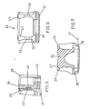
- Figures 6 and 7 illustrate detail features of the elements 22 with particular reference to the configuration of the circular apertures 26, and the shaped upper surface of the grid.
- the apertures 26 have an internal radius 43 providing a part spherical surface for engagement in operation by an internally located harpoon member carried by a helicopter.
- This part spherical internal shape of the elements 22 of the illustrated embodiment is facilitated by this invention in which the grid is made up of a number of relatively small elements 22, and this configuration can advantageously be used with a harpoon having a lower end which expands automatically on entry into the apertures 22.
- the lower end of such a harpoon has a spherical periphery when expanded to co-operate with the internal spherical surface 43 of the elements 22 to provide adequate gripping and haul-down strengths, as well as an automatic pivoting of the mated parts to ensure correct engagement in the event that the harpoon is not in exact vertical alignment with one of the apertures.
- the sloping upper surface 47 around the apertures 26 serves to guide such a harpoon member into the aperture.
- the internal shape of the apertures is modified for engagement by a harpoon adapted to grip around the bar-type sections formed between adjacent apertures 26.
- a harpoon adapted to grip around the bar-type sections formed between adjacent apertures 26.
- the elements 22 are arranged in parallel rows and that adjacent rows of elements 22 are offset longitudinally, and it is important to note that such a configuration can be achieved without requiring the manufacture of different size elements.
- the shorter element at the end of one row is achieved by cutting an element 22 across its width, the remaining portion of the cut element being assembled at the other end of the next row.
- Such a configuration may provide improved load spreading characteristics compared with a grid in which the lateral boundaries of the rows of elements 22 are aligned across the width of the grid 20.
- the guide rails 28 and one of the lateral doubling plates 40 are attached to the deck 21 for example by welding. If longitudinal retaining means are required, for example to form part of a trackway 24 as hereinbefore described, the doubling plates 35 are also welded to the deck 21. The closing beam 39 is then bolted to doubling plate 40.
- the required number of elements 22 are then slid along the guide rails 28 to abut the beam 39, an appropriate number being cut as hereinbefore described if a staggered configuration is required.
- the second doubling plate 40 is attached to the deck 21 and the assembly is closed by fitment of the second lateral closing beam 39 and (where required) the rectangular locking bar.
- the grid assembly 20 illustrated in Figure 1 is made up of 108 identical elements 22, and has overall dimensions of 2.7 metres long and 2.1 metres wide.
- the actual shape of the apertures can be of any desired form to suit different harpoon configurations, and could be of square, rectangular or oval shape instead of the circular shape hereinbefore described.
- the grid assembly 20 is not limited to being mounted on a deck surface and could, for example, be located in a well so that an upper surface is flush with a surrounding deck surface. In such an installation, the walls of the well could be utilised as one or more of the retaining means previously described in relation to the illustrated embodiments.
- the size of the elements 22 is not limited to that hereinbefore described and, in practice, may be as large as the casting process allows.
Landscapes
- Engineering & Computer Science (AREA)
- Mechanical Engineering (AREA)
- Aviation & Aerospace Engineering (AREA)
- Bridges Or Land Bridges (AREA)
- Laminated Bodies (AREA)
Claims (13)
Applications Claiming Priority (2)
| Application Number | Priority Date | Filing Date | Title |
|---|---|---|---|
| GB8037807 | 1980-11-25 | ||
| GB8037807 | 1980-11-25 |
Publications (2)
| Publication Number | Publication Date |
|---|---|
| EP0052966A1 EP0052966A1 (fr) | 1982-06-02 |
| EP0052966B1 true EP0052966B1 (fr) | 1985-08-21 |
Family
ID=10517549
Family Applications (1)
| Application Number | Title | Priority Date | Filing Date |
|---|---|---|---|
| EP81305228A Expired EP0052966B1 (fr) | 1980-11-25 | 1981-11-03 | Système d'amarrage pour avion |
Country Status (4)
| Country | Link |
|---|---|
| US (1) | US4420131A (fr) |
| EP (1) | EP0052966B1 (fr) |
| JP (1) | JPS57114798A (fr) |
| DE (1) | DE3171939D1 (fr) |
Families Citing this family (6)
| Publication number | Priority date | Publication date | Assignee | Title |
|---|---|---|---|---|
| FR2606733B1 (fr) * | 1986-11-19 | 1991-04-26 | France Etat Armement | Dispositif de reception et de maintien pour systemes d'accrochage de charge ou d'engins |
| US4836472A (en) * | 1987-01-27 | 1989-06-06 | R. Frank Sutter | Fire retardant helicopter deck |
| US7484589B2 (en) * | 2004-03-04 | 2009-02-03 | The Boeing Company | Apparatus and method for reducing aircraft noise and acoustic fatigue |
| EP2465778B1 (fr) | 2010-12-16 | 2013-06-19 | Eurocopter Deutschland GmbH | Élément d'ancrage et dispositif d'amarrage pour avion |
| DE102013217711A1 (de) | 2013-09-05 | 2015-03-05 | Robert Bosch Gmbh | Landestelle für einen Hubschrauber und Hubschrauber |
| GB201900888D0 (en) * | 2019-01-22 | 2019-03-13 | Nuclear Energy Components Ltd | Surface assembly |
Family Cites Families (3)
| Publication number | Priority date | Publication date | Assignee | Title |
|---|---|---|---|---|
| FR1253269A (fr) * | 1959-12-28 | 1961-02-10 | Sud Aviation | Procédé et dispositif d'immobilisation automatique notamment pour aérodynes et, plus particulièrement, pour hélicoptères |
| BE792040A (fr) * | 1972-04-19 | 1973-03-16 | France Etat | Dispositif de reception et de maintien pour systemes d'accrochage utilises dans l'amarrage de charges ou d'engins sur une plateforme oscillante |
| US4222695A (en) * | 1979-08-13 | 1980-09-16 | Sarides Anthanase K | Floor matting |
-
1981
- 1981-11-03 DE DE8181305228T patent/DE3171939D1/de not_active Expired
- 1981-11-03 EP EP81305228A patent/EP0052966B1/fr not_active Expired
- 1981-11-03 US US06/317,785 patent/US4420131A/en not_active Expired - Fee Related
- 1981-11-24 JP JP56187088A patent/JPS57114798A/ja active Pending
Also Published As
| Publication number | Publication date |
|---|---|
| JPS57114798A (en) | 1982-07-16 |
| EP0052966A1 (fr) | 1982-06-02 |
| US4420131A (en) | 1983-12-13 |
| DE3171939D1 (en) | 1985-09-26 |
Similar Documents
| Publication | Publication Date | Title |
|---|---|---|
| JPS6047152B2 (ja) | 浮遊性部材の接合装置 | |
| US2990920A (en) | Structural building elements | |
| EP1179472A3 (fr) | Système de chargement de fret pour avion | |
| US4420131A (en) | Mooring devices | |
| US3797099A (en) | Method for forming a ship hull section | |
| JPH0361895A (ja) | 粒子保持フィルタを持つ原子炉の燃料集合体の下部コネクタ | |
| EP0088238B1 (fr) | Dispositif pour transporter des pâtons à travers une chambre de fermentation et/ou un four | |
| DE2913486B2 (de) | Laufkran mit an den Enden eines Brückenträgers vorhandenen Kopfträgern | |
| US4712499A (en) | Method of mounting blister on ship's hull in dry dock | |
| DE3622690A1 (de) | Katalysatorkorb fuer die denitrierung | |
| US2359548A (en) | Portable deck for airplane runways and the like | |
| DE208298T1 (de) | Vorrichtung zum kuehlen eines blechstreifens. | |
| EP0202863A2 (fr) | Structure porteuse pour panneaux de criblage | |
| EP0197884B1 (fr) | Grille porteuse pour un panier à catalyseurs | |
| DE3021899A1 (de) | Vorrichtung zum anbringen eines zusaetzlichen decks in fahrzeugen. | |
| US2369733A (en) | Portable deck | |
| US3301149A (en) | Portable deck | |
| DE1459718C3 (de) | Metallplanke für den Bodenbelag und Bodenbelag einer Start- und Landebahn | |
| US4483525A (en) | Sawbuck | |
| DE933678C (de) | Einzelschwimmkoerper fuer zusammengesetzte Schwimmkoerper zum Tragen oder Befoerdern von Lasten | |
| IE36397L (en) | Barrier member | |
| DE8529532U1 (de) | Bausatz zum Ausfüttern | |
| EP0236832A3 (fr) | Dispositif pour le guidage flottant de bandes de matière au moyen d'un gaz ou d'un liquide | |
| JPS6031990Y2 (ja) | 貨物船の上甲板上の薄板箱形構造物 | |
| EP0112457A3 (fr) | Dispositif pour raccorder des rails à profil en I, en particulier pour des voies à suspension à rail unique |
Legal Events
| Date | Code | Title | Description |
|---|---|---|---|
| PUAI | Public reference made under article 153(3) epc to a published international application that has entered the european phase |
Free format text: ORIGINAL CODE: 0009012 |
|
| AK | Designated contracting states |
Designated state(s): BE DE FR GB IT NL SE |
|
| RAP1 | Party data changed (applicant data changed or rights of an application transferred) |
Owner name: WESTLAND PLC |
|
| 17P | Request for examination filed |
Effective date: 19820519 |
|
| ITF | It: translation for a ep patent filed | ||
| GRAA | (expected) grant |
Free format text: ORIGINAL CODE: 0009210 |
|
| AK | Designated contracting states |
Designated state(s): BE DE FR GB IT NL SE |
|
| REF | Corresponds to: |
Ref document number: 3171939 Country of ref document: DE Date of ref document: 19850926 |
|
| ET | Fr: translation filed | ||
| PGFP | Annual fee paid to national office [announced via postgrant information from national office to epo] |
Ref country code: NL Payment date: 19851130 Year of fee payment: 5 |
|
| REG | Reference to a national code |
Ref country code: GB Ref legal event code: 732 |
|
| PLBE | No opposition filed within time limit |
Free format text: ORIGINAL CODE: 0009261 |
|
| STAA | Information on the status of an ep patent application or granted ep patent |
Free format text: STATUS: NO OPPOSITION FILED WITHIN TIME LIMIT |
|
| 26N | No opposition filed | ||
| PG25 | Lapsed in a contracting state [announced via postgrant information from national office to epo] |
Ref country code: SE Effective date: 19861104 |
|
| PG25 | Lapsed in a contracting state [announced via postgrant information from national office to epo] |
Ref country code: BE Effective date: 19861130 |
|
| BERE | Be: lapsed |
Owner name: WESTLAND P.L.C. Effective date: 19861130 |
|
| PG25 | Lapsed in a contracting state [announced via postgrant information from national office to epo] |
Ref country code: NL Effective date: 19870601 |
|
| NLV4 | Nl: lapsed or anulled due to non-payment of the annual fee | ||
| GBPC | Gb: european patent ceased through non-payment of renewal fee | ||
| PG25 | Lapsed in a contracting state [announced via postgrant information from national office to epo] |
Ref country code: FR Free format text: LAPSE BECAUSE OF NON-PAYMENT OF DUE FEES Effective date: 19870731 |
|
| PG25 | Lapsed in a contracting state [announced via postgrant information from national office to epo] |
Ref country code: DE Effective date: 19870801 |
|
| REG | Reference to a national code |
Ref country code: FR Ref legal event code: ST |
|
| PG25 | Lapsed in a contracting state [announced via postgrant information from national office to epo] |
Ref country code: GB Effective date: 19881118 |
|
| EUG | Se: european patent has lapsed |
Ref document number: 81305228.9 Effective date: 19870901 |