EP0053093A1 - Method of untwisting a length of a textile yarn, and device for applying this method - Google Patents
Method of untwisting a length of a textile yarn, and device for applying this method Download PDFInfo
- Publication number
- EP0053093A1 EP0053093A1 EP81810435A EP81810435A EP0053093A1 EP 0053093 A1 EP0053093 A1 EP 0053093A1 EP 81810435 A EP81810435 A EP 81810435A EP 81810435 A EP81810435 A EP 81810435A EP 0053093 A1 EP0053093 A1 EP 0053093A1
- Authority
- EP
- European Patent Office
- Prior art keywords
- wire
- fibers
- vibrations
- flexible element
- vibrating member
- Prior art date
- Legal status (The legal status is an assumption and is not a legal conclusion. Google has not performed a legal analysis and makes no representation as to the accuracy of the status listed.)
- Granted
Links
- 239000004753 textile Substances 0.000 title claims abstract description 8
- 238000000034 method Methods 0.000 title claims description 26
- 239000000835 fiber Substances 0.000 claims abstract description 54
- 230000000717 retained effect Effects 0.000 claims description 15
- 210000002105 tongue Anatomy 0.000 claims description 14
- 239000012528 membrane Substances 0.000 claims description 7
- 238000009987 spinning Methods 0.000 claims description 6
- 238000010009 beating Methods 0.000 claims description 2
- 238000011144 upstream manufacturing Methods 0.000 claims 1
- 238000005304 joining Methods 0.000 abstract description 4
- 238000002360 preparation method Methods 0.000 abstract description 4
- 238000009826 distribution Methods 0.000 description 3
- 238000006073 displacement reaction Methods 0.000 description 2
- 229920001971 elastomer Polymers 0.000 description 2
- 238000000926 separation method Methods 0.000 description 2
- 244000043261 Hevea brasiliensis Species 0.000 description 1
- 229910000831 Steel Inorganic materials 0.000 description 1
- 230000000712 assembly Effects 0.000 description 1
- 238000000429 assembly Methods 0.000 description 1
- 210000001520 comb Anatomy 0.000 description 1
- 230000000694 effects Effects 0.000 description 1
- 230000008030 elimination Effects 0.000 description 1
- 238000003379 elimination reaction Methods 0.000 description 1
- 239000000463 material Substances 0.000 description 1
- 229920003052 natural elastomer Polymers 0.000 description 1
- 229920001194 natural rubber Polymers 0.000 description 1
- 230000010355 oscillation Effects 0.000 description 1
- 239000007787 solid Substances 0.000 description 1
- 239000010959 steel Substances 0.000 description 1
- 238000004804 winding Methods 0.000 description 1
Images

Classifications
-
- D—TEXTILES; PAPER
- D02—YARNS; MECHANICAL FINISHING OF YARNS OR ROPES; WARPING OR BEAMING
- D02G—CRIMPING OR CURLING FIBRES, FILAMENTS, THREADS, OR YARNS; YARNS OR THREADS
- D02G3/00—Yarns or threads, e.g. fancy yarns; Processes or apparatus for the production thereof, not otherwise provided for
- D02G3/22—Yarns or threads characterised by constructional features, e.g. blending, filament/fibre
-
- B—PERFORMING OPERATIONS; TRANSPORTING
- B65—CONVEYING; PACKING; STORING; HANDLING THIN OR FILAMENTARY MATERIAL
- B65H—HANDLING THIN OR FILAMENTARY MATERIAL, e.g. SHEETS, WEBS, CABLES
- B65H69/00—Methods of, or devices for, interconnecting successive lengths of material; Knot-tying devices ;Control of the correct working of the interconnecting device
- B65H69/06—Methods of, or devices for, interconnecting successive lengths of material; Knot-tying devices ;Control of the correct working of the interconnecting device by splicing
-
- B—PERFORMING OPERATIONS; TRANSPORTING
- B65—CONVEYING; PACKING; STORING; HANDLING THIN OR FILAMENTARY MATERIAL
- B65H—HANDLING THIN OR FILAMENTARY MATERIAL, e.g. SHEETS, WEBS, CABLES
- B65H2701/00—Handled material; Storage means
- B65H2701/30—Handled filamentary material
- B65H2701/31—Textiles threads or artificial strands of filaments
Definitions
- the subject of the present invention is a method for undoing a portion of a textile thread, held by at least one of its ends, and a device for implementing this method.
- the resistance of the piecing is extremely low because the two bundles of fibers are wound in a helix one around the other, most of the fibers then not participating in the strength of the piecing.
- the method according to the present invention is characterized in that vibrations are communicated to the fibers so as to reduce their coefficient of friction and cause their dislocation, and that the fibers thus dislocated are subjected to a force directed so as to separate the fibers not retained at said end.
- the device for implementing the method, also subject of the invention is characterized in that it comprises means for holding one end of the portion of wire to be undone, at least one vibrating member, means for guiding said portion of wire in the immediate vicinity of said vibrating member, means for driving this vibrating member and means for eliminating from this portion of wire fibers not retained at said end.
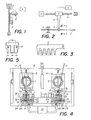
- FIG. 1 shows a portion of wire F, one end of which is fixed at P and the other end of which carries a weight M of approximately 5 to 10 g.
- the thread Under the action of the latter the thread will become untwisted. If it is a thread obtained on a slider ring loom, the weight M will fall after a certain number of turns carrying with it the untwisted fibers which are not retained in P. On the other hand, if it s is a yarn obtained by the "open-end" spinning process, all the fibers will not participate in the untwisting since some of them did not participate directly in the average twist of the yarn, so that the weight M will be retained by these fibers and will not fall.
- FIG 1 shows, in addition, a vibrating blade L fixed on a support so that it is close to and parallel to the wire.
- An electromagnet E supplied with current pulses by a generator G, is arranged so as to make the blade L vibrate.
- vibrations are communicated to the fibers of the wire F, which will have the consequence the reduction of their coefficient of friction and their dislocation, so that all the fibers not retained in P will separate under the action of the weight M and this one will fall after a certain time as far as the frequencies of the blade L and the pendulum system formed by the wire F and the weight M are different and non-harmonic.
- the frequency of the blade L is 100 Hz and the separation of the fibers, under the action of the weight M, occurs in a few seconds.
- the free end of the wire F a bundle consisting of all the fibers retained at P, the length of which corresponds substantially to the average length of the fibers. This is an important factor in obtaining good bonding of the wire.
- the device represented in FIG. 2 comprises a comb C associated with a sonotrode S connected, by a transducer T, to a pulse generator G.
- the transducer T is associated with a worm screw V driven by a motor D.
- the vibrations reducing the coefficient of friction of the fibers cause the dislocation of the latter and facilitate the progression of the teeth of the comb C.
- the son is undone and the fibers not retained in P are separated and eliminated.
- the vibrating member is driven pneumatically, the pressurized air being widely available in the textile industry and the range of frequencies then depending only on the natural frequency of the vibrating member which can be sized accordingly.
- the energy transmitted to the wire can be greater than the energy developed in the device described above.
- FIG. 4 The apparatus illustrated in FIG. 4 is essentially that shown and described in the specification of Swiss patent No ... (patent application 6379/78) to which reference may be made for more details, given that this description will be limited to the elements necessary for understanding the invention.
- This device essentially comprises two pins 1 and 2 mounted rotatably each in a support 3 and 4 respectively, mounted oscillating in a frame 5 along an axis orthogonal to that of the spindle.
- Each of these pins 1 and 2 ends at one of its ends with a circular head 6, respectively 7, split radially 6a, respectively 7a, to allow the wire F to engage in this circular head 6, respectively 7 and s 'wrap around pin 1, respectively 2.
- the supports 3 and 4 are likely to occupy two positions each, one in which the pins 1 and 2 are coaxial and the other in which they are parallel one to the other. In this latter position, shown in FIG. 4, each of pins 1 and 2 is located opposite the end of a duct 8, respectively 9, connected to a source of air suction 10.
- each of the conduits is formed of two parts 11a and 11b, respectively 12a and 12b, which extend substantially longitudinally in the conduit. These two parts are fixed to each other, for example by means of screws 13 (fig. 5).
- a flexible flapping element constituted by a tongue 14, respectively 15, integral with a fixing lug 16, respectively .17 clamped between said parts end 11a and 11b, respectively 12a and 12b and forming with the respective tongue a T.
- These beat elements are preferably cut from a rubber membrane about 0.25 mm thick.
- Each of the tongues 14 and 15 is preferably located near the longitudinal axis of the respective conduit in order to be able to float freely therein.
- the section of these conduits 8 and 9, at least in their part in which the tongue 14, respectively 15, extends, is preferably square or rectangular so that the free end of the tongue can beat against two opposite walls of the drove.
- a comb 18 and 19 respectively is fixed.
- a pair of scissors formed of two steel blades 22 and 23, one of which 22 is slidably mounted relative to the other 23 and each of which has an opening 24 and 25 respectively, is arranged transversely to each of the suction conduits 8 and 9.
- each of them is introduced into one of the conduits 8 and 9 in which there is a slight depression created by the suction source 10.
- the pins 1 and 2 are rotated in opposite directions, so that on each of them a portion of respective wire is wound because of its engagement in the slot 6a, respectively 7a, formed in the head 6, respectively 7, of spindle 1, respectively 2.
- elbow formed in each conduit 8 and 9 below the scissors 22, 23, allows, during the winding of the wire on each of the pins 1 and 2, to induce a certain distortion of the wire in the portion between the spit and the elbow.
- the direction of twist of the fibers in this portion must be opposite to the direction of rotation of the spindle.
- each of the two assemblies associated with the connecting device and formed of a conduit 8, respectively 9, open at both ends, of a flexible beat element 14, respectively 15, and of a source d air suction constitutes a device implementing the method according to the present invention.
- this device makes it possible to undo the wires which hitherto could not have been under the sole effect of the means normally included in such a reattachment device, that is to say by means of the combs 18 and 19 and air flow in conduits 8 and 9.
- the wire is defeated in a time not exceeding one second. It is obvious that this device is far more efficient than the two devices shown in FIGS. 1 and 2 respectively. It is much more reliable, much simpler to carry out and makes it possible to reduce the duration of the operation.
- Figures 6 and 7 illustrate another embodiment of the pneumatic device associated with a connecting device which is the subject of Swiss patent No .... (patent application No 10448/79) to which we can refer to obtain more details on the actual piecing.
- Figs. 6 and 7 illustrate only one of the two oscillating supports 28, carrying a spindle 29 rotatably mounted about an axis orthogonal to that of oscillation of the support 28 and provided with a head 29a slotted ra dialement.
- the other support, not shown, is perfectly similar to support 28 and is not necessary for understanding the invention since the operation of undoing the ends of the wire to be attached is carried out symmetrically on the two supports.
- the support 28 is integral with a tubular shaft 30 to which is fixed a radial arm 31 connected to the rod of a drive piston 32.
- An arm 33 one end of which carries a bevel gear 34, passes through the tubular shaft 30 This pinion 34 is engaged with a second bevel gear 35 wedged on the shaft of the spindle 29.
- a plate 36 having essentially a channel 37 and a distribution chamber 40 into which opens an intake duct 38 connected to a pressurized air source 39 is fixed on the support 28.
- the distribution chamber 40 has a nozzle 41 at the level of the channel 37, formed by a lip 42 forming a flow along the surface of this channel.
- a bypass conduit 43 connects the chamber 40 to a bore 44 in which is fixed a cone 45 whose apex is adjacent to the bottom of the channel 37 and whose axis of revolution is perpendicular to the bypass conduit 43.
- a second tubular shaft 46 connected to the rod of a jack 47 by a radial arm 48, is pivotally mounted around the tubular shaft 30, as well as through a frame 49.
- This tubular shaft 46 is integral with a second radial arm 50 at the end of which is pivoted a fixing rod 51 connected to a frame 52.
- a second fixing rod 53, fixed to the same frame 52 is pivoted through an arm 54 parallel to the radial arm 50 and articulated to the end of another radial arm 55 secured to the tubular shaft 30, so as to form a deformable parallelogram, carrying the frame 52.
- the frame 52 carries a natural rubber membrane 56 of about 0.25 mm thick, which has a longitudinal slot 56a and two transverse slots 56b delimiting two tabs 56c whose longitudinal ends are adjacent.
- This frame 52 is capable of occupying two positions relative to the support 28, controlled by the jack 47. In one of these positions, the frame 52 is adjacent to the plate 36 and its channel 37, in the other, shown in lines mixed with, fig. 6, it is excluded.
- Two suction tubes 57 and 58, connected to a suction source 59 are arranged on either side of the oscillating support 28 and its plate 36, when the support is in the position shown in FIG. 6. These tubes serve to tension the wire F through the plate 36 while the frame 52 is spaced from this plate and to pass it against the edge of the slotted head 29a of the pin 29.
- the pin 29 is entrained in rotation using the shaft 33 and the pinions 34 and 35.
- the wire F enters the slot of the head 29a and is wound around the spindle 29.
- the direction of rotation of the spindle is chosen so as to untwist the portion of wire between the head 29a and the suction tube 58, as explained in detail in the aforementioned Swiss patent.
- the frame 52 carrying the membrane 56 is brought, by virtue of its carrying system with deformable parallelogram 50, 54 and 55, against the plate 36, so that the membrane 56 covers the wire located in channel 37.
- Pressurized air is then sent to the distribution chamber 40 and from this into the channel 37.
- the air flow passing through the channel vibrates the tabs 56c which beat the wire which is at the same time subjected to a tensile force due to the friction of the air current.
- the yarn breaks completely and the fibers not retained by the spindle 29 are separated and eliminated by the air stream.
- the device according to the invention incorporated in the connecting device, is formed from the channel 37, the membrane 56 with its tongues 56c, and the source of pressurized air (with the conduits connecting it to the channel 37).
- the vibrating elements 56c driven in vibration by the air current, have been dimensioned to vibrate at frequencies of the order of 500 to 2000 Hz. It has been observed that it is in this frequency range with elements made of a material as flexible as rubber of the order of 0.2 to 0.3 mm thick capable of vibrating, at these frequencies, at amplitudes of the order of a millimeter, as the results are the best.
Landscapes
- Engineering & Computer Science (AREA)
- Mechanical Engineering (AREA)
- Textile Engineering (AREA)
- Spinning Or Twisting Of Yarns (AREA)
- Yarns And Mechanical Finishing Of Yarns Or Ropes (AREA)
- Treatment Of Fiber Materials (AREA)
- Replacing, Conveying, And Pick-Finding For Filamentary Materials (AREA)
- Preliminary Treatment Of Fibers (AREA)
- Coating With Molten Metal (AREA)
Abstract
Description
La présente invention a pour objet un procédé pour défaire une portion d'un fil textile, tenue par au moins une de ses extrémités, et un dispositif pour la mise en oeuvre de ce procédé.The subject of the present invention is a method for undoing a portion of a textile thread, held by at least one of its ends, and a device for implementing this method.
Pour rattacher deux fils textiles, on peut faire un noeud qui donne une rattache solide mais visible. On peut également faire une rattache sans noeud par différents procédés. Cette rattache est moins visible que le noeud, mais elle affaiblit généralement le fil. L'idéal consiste à recréer les conditions de torsion initiale du fil, comme proposé, par exemple, dans le fascicule du brevet US 2 362 801 ou dans celui du brevet US 3 903 680. Il ressort de ce dernier que pour obtenir une bonne résistance de la rattache, les fibres des deux extrémités à rattacher doivent être préalablement séparées de manière qu'elles puissent ensuite s'interpénétrer avant de les soumettre à une torsion. Si l'on se contente de tordre ensemble les deux extrémités sans qu'il y ait au préalable interpénétration des fibres, la résistance de la rattache est extrêmement faible du fait que les deux faisceaux de fibres s'enroulent en hélice l'un autour de l'autre, la plupart des fibres ne participant alors pas à la résistance de la rattache.To tie two textile threads, you can make a knot that gives a solid but visible connection. You can also make a knotless knot by different methods. This tie is less visible than the knot, but it generally weakens the thread. The ideal consists in recreating the conditions of initial twist of the wire, as proposed, for example, in the specification of US Pat. No. 2,362,801 or that of US Patent 3,903,680. It appears from the latter that to obtain good resistance of the reattachment, the fibers of the two ends to be reattached must be separated beforehand so that they can then interpenetrate before subjecting them to a twist. If one is content to twist the two ends together without there being interpenetration of the fibers beforehand, the resistance of the piecing is extremely low because the two bundles of fibers are wound in a helix one around the other, most of the fibers then not participating in the strength of the piecing.
Pour obtenir un faisceau de fibres séparées en vue de permettre leur interpénétration avec un autre faisceau de fibres, formé de la même manière à l'autre extrémité de fil à rattacher, il suffit de détordre chacune de ces extrémités et de disposer les fibres parallèlement les unes aux autres et séparées les unes des autres. Or, la séparation des fibres par détorsion n'est possible que lorsqu'il s'agit d'un fil obtenu par filage sur un métier à anneau-curseur. Par contre, il n'est pas possible de procéder ainsi notamment avec des fils obtenus par le procédé de filage dit "open-end" ou avec des fils retors. Dans le premier cas, les fibres ne forment pas des hélices plus ou moins parallèles et régulières, mais sont beaucoup moins bien ordonnées, certaines s'étendent longitudinalement et d'autres sont enroulées autour. Par conséquent, une simple détorsion ne suffit pas à défaire une portion d'un tel fil puisque toute les fibres ne sont pas tordues ensemble. Dans un fil retors, il faut d'abord défaire le retors et ensuite défaire chaque fil, la torsion de retors et celle des fils étant de sens contraire.To obtain a bundle of separate fibers in order to allow their interpenetration with another bundle of fibers, formed in the same way at the other end of the wire to be attached, it suffices to untwist each of these ends and to arrange the fibers in parallel to each other and separate from each other. However, the separation of the fibers by twisting is only possible when it is a yarn obtained by spinning on a ring-cursor loom. On the other hand, it is not possible to do so in particular with threads obtained by the so-called "open-end" spinning process or with plied threads. In the first case, the fibers do not form more or less parallel and regular helices, but are much less well ordered, some extend longitudinally and others are wound around. Consequently, a simple twist is not sufficient to undo a portion of such a thread since all the fibers are not twisted together. In a twisted yarn, you must first undo the twisted and then undo each thread, the twisting of twists and that of the threads being in the opposite direction.
Il s'avère par conséquent que le procédé selon le brevet US 3 903 680 n'est pas adapté à tous les types de fil et qu'il ne peut être mis en oeuvre que s'il est possible de défaire les fibres par un autre moyen que la détorsion.It therefore appears that the method according to US Pat. No. 3,903,680 is not suitable for all types of yarn and that it can only be implemented if it is possible to undo the fibers by another way that untwisting.
C'est précisément le but que la présente invention se propose d'at- teindre, afin de permettre la rattache notamment par torsion de fibres s'interpénétrant, quel que soit le type de fil.This is precisely the aim that the present invention proposes to achieve, in order to allow the joining in particular by twisting of interpenetrating fibers, whatever the type of yarn.
A cet effet, le procédé selon la présente invention est caractérisé par le fait que l'on communique aux fibres des vibrations de manière à réduire leur coefficient de frottement et à provoquer leur dislocation, et que l'on soumet les fibres ainsi disloquées à une force dirigée de manière à séparer les fibres non retenues à ladite extrémité.To this end, the method according to the present invention is characterized in that vibrations are communicated to the fibers so as to reduce their coefficient of friction and cause their dislocation, and that the fibers thus dislocated are subjected to a force directed so as to separate the fibers not retained at said end.
Le dispositif pour la mise en oeuvre du procédé, également objet de l'invention, est caractérisé par le fait qu'il comprend des moyens pour tenir une extrémité de la portion de fil à défaire, au moins un organe vibrant, des moyens pour guider ladite portion de fil à proximité immédiate dudit organe vibrant, des moyens d'entraînement de cet organe vibrant et des moyens pour éliminer de cette portion de fil les fibres non retenues à ladite extrémité.The device for implementing the method, also subject of the invention, is characterized in that it comprises means for holding one end of the portion of wire to be undone, at least one vibrating member, means for guiding said portion of wire in the immediate vicinity of said vibrating member, means for driving this vibrating member and means for eliminating from this portion of wire fibers not retained at said end.
Les caractéristiques et les avantages du procédé et du dispositif pour sa mise en oeuvre ressortiront plus clairement de la description détaillée qui suit et dans laquelle on décrit le principe utilisé dans le procédé et quelques formes d'exécution du dispositif pour la mise en oeuvre du procédé en se référant aux dessins annexés, donnés à titre d'exemple, dans lesquels :
- La figure 1 illustre schématiquement le principe utilisé dans le procédé.
- La figure 2 représente schématiquement une première forme d'exécution du dispositif.
- La figure 3 est une coupe, à plus grande échelle, selon la ligne III-III de la figure 2.
- La figure 4 est une vue en élévation d'un appareil de rattache, partiellement coupé, muni de deux dispositifs se)on une deuxième forme d'exécution.
- La figure 5 est une coupe, à plus grande échelle, selon la ligne V-V de la figure 4.
- La figure 6 est une vue en élévation d'une variante de l'appareil de la figure 4, muni d'un dispositif selon une troisième forme d'exécution.
- La figure 7 est une vue selon la ligne VII-VII de la figure 6.
- Figure 1 schematically illustrates the principle used in the process.
- FIG. 2 schematically represents a first embodiment of the device.
- Figure 3 is a section, on a larger scale, along line III-III of Figure 2.
- Figure 4 is an elevational view of a connecting device, partially cut, provided with two devices) is a second embodiment.
- Figure 5 is a section, on a larger scale, along the line VV in Figure 4.
- Figure 6 is an elevational view of a variant of the apparatus of Figure 4, provided with a device according to a third embodiment.
- Figure 7 is a view along line VII-VII of Figure 6.
La figure 1 montre une portion de fil F dont une extrémité est fixée en P et dont l'autre extrémité porte un poids M d'environ 5 à 10 g. Sous l'action de ce dernier le fil va se détordre. S'il s'agit d'un fil obtenu sur un métier à anneau-curseur, le poids M tombera après un certain nombre de tours entraînant avec lui les fibres détordues qui ne sont pas retenues en P. Par contre, s'il s'agit d'un fil obtenu par le procédé de filage "open-end", toutes les fibres ne participeront pas à la détorsion puisque certaines d'entre elles n'ont pas participé directement à la torsion moyenne du fil, de sorte que le poids M sera retenu par ces fibres et ne tombera pas.FIG. 1 shows a portion of wire F, one end of which is fixed at P and the other end of which carries a weight M of approximately 5 to 10 g. Under the action of the latter the thread will become untwisted. If it is a thread obtained on a slider ring loom, the weight M will fall after a certain number of turns carrying with it the untwisted fibers which are not retained in P. On the other hand, if it s is a yarn obtained by the "open-end" spinning process, all the fibers will not participate in the untwisting since some of them did not participate directly in the average twist of the yarn, so that the weight M will be retained by these fibers and will not fall.
La figure 1 montre, en outre, une lame vibrante L fixée sur un support de manière qu'elle soit près du fil et parallèle à celui-ci. Un électro-aimant E, alimenté en impulsions de courant par un générateur G, est disposé de manière à pouvoir faire vibrer la lame L. En faisant vibrer la lame L, on communique des vibrations aux fibres du fil F, ce qui aura pour conséquence la réduction de leur coefficient de frottement et leur dislocation, de sorte que toutes les fibres non retenues en P se sépareront sous l'action du poids M et celui-ci tombera au bout d'un certain temps pour autant que les fréquences de la lame L et du système de pendule formé du fil F et du poids M soient différentes et non harmoniques. En l'occurence, la fréquence de la lame L est de 100 Hz et la séparation des fibres, sous l'action du poids M, se produit en quelques secondes. On obtient donc à l'extrémité libre du fil F un faisceau constitué de toutes les fibres retenues en P, dont la longueur correspond sensiblement à la longueur moyenne des fibres. Ceci est un facteur important pour obtenir une bonne rattache du fil.Figure 1 shows, in addition, a vibrating blade L fixed on a support so that it is close to and parallel to the wire. An electromagnet E, supplied with current pulses by a generator G, is arranged so as to make the blade L vibrate. By making the blade L vibrate, vibrations are communicated to the fibers of the wire F, which will have the consequence the reduction of their coefficient of friction and their dislocation, so that all the fibers not retained in P will separate under the action of the weight M and this one will fall after a certain time as far as the frequencies of the blade L and the pendulum system formed by the wire F and the weight M are different and non-harmonic. In this case, the frequency of the blade L is 100 Hz and the separation of the fibers, under the action of the weight M, occurs in a few seconds. There is therefore obtained at the free end of the wire F a bundle consisting of all the fibers retained at P, the length of which corresponds substantially to the average length of the fibers. This is an important factor in obtaining good bonding of the wire.
L'expérience décrite ci-dessus démontre l'efficacité du principe utilisé dans le procédé selon la présente invention, principe selon lequel les vibrations communiquées aux fibres d'un fil provoquent la diminution de leur coefficient de frottement et la dislocation de toutes les fibres, donc également de celles qui n'ont pas participé à la torsion moyenne du fil, ce que la détorsion seule ne permet pas d'obtenir.The experience described above demonstrates the effectiveness of the principle used in the method according to the present invention, principle according to which the vibrations imparted to the fibers of a wire cause the reduction of their coefficient of friction and the dislocation of all the fibers, thus also of those which did not take part in the average twist of the wire, which the untwisting alone does not make it possible to obtain.
Le dispositif représenté à la figure 2 comprend un peigne C associé à une sonotrode S reliée, par un transducteur T, à un générateur d'impulsions G. Le transducteur T est associé à une vis sans fin V entraînée par un moteur D.The device represented in FIG. 2 comprises a comb C associated with a sonotrode S connected, by a transducer T, to a pulse generator G. The transducer T is associated with a worm screw V driven by a motor D.
Pour défaire la portion de fil F, dont une extrémité est tenue en P, on insère les dents du peigne C dans le fil F (fig. 3) et on les met en vibration au moyen de la sonotrode S. Comme on le voit à la figure 3, les dents du peigne C sont agencées pour ouvrir le fil F et faire en sorte que les fibres prises entre deux dents conservent une certaine liberté de sorte que, lorsque le peigne C vibre, ses dents frappent les fibres et leur communiquent ainsi des vibrations. Simultanément, l'ensemble formé du peigne C, de la sonotrode S et du transducteur T est entraîné par la vis sans fin V en direction opposée au point de pincement P. Le déplacement du peigne C provoque la détorsion des fibres et la séparation (élimination) des fibres non retenues au point de pincement P. En outre, les vibrations réduisant le coefficient de frottement des fibres provoquent la dislocation de celles-ci et facilitent la progression des dents du peigne C. Dès que ce dernier arrive à une distance du point de pincement P correspondant à la longueur des fibres, le fils est défait et les fibres non retenues en P sont séparées et éliminées.To undo the portion of wire F, one end of which is held in P, insert the teeth of the comb C into the wire F (fig. 3) and put them in vibration by means of the sonotrode S. As seen in FIG. 3, the teeth of the comb C are arranged to open the wire F and ensure that the fibers caught between two teeth retain a certain freedom so that, when the comb C vibrates, its teeth strike the fibers and thus communicate to them vibrations. Simultaneously, the assembly formed by the comb C, the sonotrode S and the transducer T is driven by the worm screw V in the direction opposite to the pinch point P. The displacement of the comb C causes the fibers to untwist and separate (elimination ) fibers not retained at the pinch point P. In addition, the vibrations reducing the coefficient of friction of the fibers cause the dislocation of the latter and facilitate the progression of the teeth of the comb C. As soon as the latter arrives at a distance from the point pinch P corresponding to the length of the fibers, the son is undone and the fibers not retained in P are separated and eliminated.
Le dispositif décrit ci-dessus permet d'obtenir un résultat assez satisfaisant, mais à condition que le déplacement du peigne C soit relativement lent. Toutefois, malgré une telle précaution, il arrive souvent qu'un blocage du peigne se produise. En outre, les moyens pour faire vibrer l'organe vibrant sont assez complexes et onéreux, ce qui est évidemment un inconvénient qui porte préjudice important à l'utilisation de ce dispositif dans un appareil de rattache.The device described above makes it possible to obtain a fairly satisfactory result, but on condition that the displacement of the comb C is relatively slow. However, despite this precaution, it often happens that a blockage of the comb occurs. In addition, the means for vibrating the vibrating member are quite complex and expensive, which is obviously a drawback which causes significant harm to the use of this device in a connecting device.
C'est la raison pour laquelle on a cherché une solution dans laquelle l'organe vibrant est entraîné pneumatiquement,l'air sous pression étant largement disponible dans l'industrie textile et la gamme de fréquences ne dépendant alors que de la fréquence propre de l'organe vibrant qui peut être dimensionné en conséquence. En outre, l'énergie transmise au fil peut être supérieure à l'énergie développée dans le dispositif décrit ci-dessus.This is the reason why a solution has been sought in which the vibrating member is driven pneumatically, the pressurized air being widely available in the textile industry and the range of frequencies then depending only on the natural frequency of the vibrating member which can be sized accordingly. In addition, the energy transmitted to the wire can be greater than the energy developed in the device described above.
Deux formes d'exécution d'un tel dispositif vont maintenant être décrites, chacune dans le cadre d'un appareil de rattache auquel est associé le dispositif.Two embodiments of such a device will now be described, each in the context of a connecting device with which the device is associated.
L'appareil illustré par la figure 4 est, pour l'essentiel, celui représenté et décrit dans le fascicule du brevet suisse No... (demande de brevet 6379/78) auquel on pourra se référer pour plus de détails, étant donné que l'on limitera la présente description aux éléments nécessaires à la compréhension de l'invention.The apparatus illustrated in FIG. 4 is essentially that shown and described in the specification of Swiss patent No ... (patent application 6379/78) to which reference may be made for more details, given that this description will be limited to the elements necessary for understanding the invention.
Cet appareil comprend essentiellement deux broches 1 et 2 montées rotativement chacune dans un support 3 et 4 respectivement, monté oscillant dans un bâti 5 selon un axe orthogonale à celui de la broche. Chacune de ces broches 1 et 2 se termine à une de ses extrémités par une tête circulaire 6, respectivement 7, fendue radialement 6a, respectivement 7a, pour permettre au fil F de s'engager dans cette tête circulaire 6, respectivement 7 et de s'enrouler autour de la broche 1, respectivement 2. Les supports 3 et 4 sont susceptibles d'occuper deux positions chacun, l'une dans laquelle les broches 1 et 2 sont coaxiales et l'autre dans laquelle elles sont parallèles l'une à l'autre. Dans cette dernière position, représentée à la figure 4, chacune des broches 1 et 2 se trouve en face de l'extrémité d'un conduit 8, respectivement 9, relié à une source d'aspiration d'air 10. L'extrémité d'aspiration de chacun des conduits est formée de deux parties lla et llb, respectivement 12a et 12b, qui s'étendent sensiblement longitudinalement dans le conduit. Ces deux parties sont fixées l'une à l'autre, par exemple au moyen de vis 13 (fig. 5). Le long de ces parties d'extrémité de chacun des deux conduits 8 et 9 s'étend un élément de battement souple constitué par une languette 14, respectivement 15, solidaire d'une patte de fixation 16, respectivement .17 serrée entre les dites parties d'extrémité lla et llb, respectivement 12a et 12b et formant avec la languette respective un T. Ces éléments de battement sont découpés, de préférence, dans une membrane de caoutchouc d'environ 0,25 mm d'épaisseur. Chacune des languettes 14 et 15 se trouve, de préférence, à proximité de l'axe longitudinal du conduit respectif afin de pouvoir flotter librement dans celui-ci. La section de ces conduits 8 et 9, au moins dans leur partie dans laquelle s'étend la languette 14, respectivement 15, est, de préférence, carrée ou rectangulaire pour que l'extrémité libre de la languette puisse battre contre deux parois opposées du conduit. A proximité de l'ouverture d'admission du fil de chacun des conduits 8 et 9, est fixé un peigne 18 et 19 respectivement. Dans chacun des conduits 8 et 9 débouche un canal ,20 et 21 respectivement, destiné à l'admission d'air secondaire. Une paire de ciseaux formés de deux lames d'acier 22 et 23 dont l'une 22 est montée coulissante par rapport à l'autre 23 et dont chacune est percée d'une ouverture 24 et 25 respectivement, est disposée transversalement à chacun des conduits d'aspiration 8 et 9.This device essentially comprises two
Pour préparer les deux extrémités de fil à rattacher, on introduit chacune d'elle dans l'un des conduits 8 et 9 dans lesquels règne une légère dépression créée par la source d'aspiration 10. Lorsqu'une certaine longueur de fil est introduite dans chaque conduit, on fait tourner les broches 1 et 2 en sens opposés, de manière que sur chacune d'elle s'enroule une portion de fil respectif du fait de sa prise dans la fente 6a, respectivement 7a, pratiquée dans la tête 6, respectivement 7, de la broche 1, respectivement 2. On fait ensuite glisser les lames 22 par rapport aux lames 23 des deux paires de ciseaux, pour couper les fils dans les conduits au niveau des ouvertures 24 et 25, de manière à obtenir dans la partie supérieure de chacun des conduits 8 et 9 une portion de fil dont une extrémité est tenue par la broche respective.To prepare the two ends of the wire to be attached, each of them is introduced into one of the
Après cette opération préliminaire, identique à celle décrite dans le brevet suisse ...... (demande de brevet No 6379/78, on augmente le débit d'air aspiré à travers les conduits 8 et 9, pour mettre en vibration (battement) les languettes 14 et 15 et pour exercer une force de traction sur la portion de fil dans le conduit. Les battements de ces languettes contre les fils provoquent la dislocation des fibres dans la zone soumise à ces battements. Comme les fils sont simultanément aspirés, les fibres disloquées qui ne tiennent plus aux brins de fil enroulés sur les broches 1 et 2 respectivement, se séparent de sorte qu'un faisceau de fibres séparées apparaît à l'extrémité de chaque portion de fil défait et peut être éliminé. Le reste des opérations de rattache s'effectue comme décrit dans le brevet suisse susmentionné. Etant donné que la rattache proprement dite ne fait pas l'objet de la présente invention, ces opérations ne seront pas décrites ici et l'on se reportera à ce brevet pour obtenir davantage de détails à ce sujet.After this preliminary operation, identical to that described in the Swiss patent ...... (patent application No 6379/78, the flow of air sucked through the
Il est à noter que le coude ménagé dans chaque conduit 8 et 9 au-dessous des ciseaux 22, 23, permet, lors de l'enroulement du fil sur chacune des broches 1 et 2, d'induire une certaine détorsion du fil dans la portion comprise entre la broche et le coude. Le sens de torsion des fibres dans cette portion doit être opposé au sens de rotation de la broche. Si, dans un fil "open-end" une partie appréciable des fibres ne sont pas tordues, les vibrations communiquées à ces fibres par des languettes 14 et 15, diminuent leur coefficient de frottement, de sorte que toutes les fibres qui ne sont pas retenues par les broches 1 et 2 sont éliminées par le courant d'air circulant dans les conduits, seules les fibres disloquées, retenues par les broches, restant dans les conduits et formant les deux extrémités de fil à rattacher par torsion.It should be noted that the elbow formed in each
Il est facile de voir de la description des fig. 4 et 5 que chacun des deux ensembles, associé à l'appareil de rattache et formé d'un conduit 8, respectivement 9, ouvert aux deux extrémités, d'un élément de battement souple 14, respectivement 15, et d'une source d'aspiration d'air, constitue un dispositif mettant en oeuvre le procédé selon la présente invention.It is easy to see from the description of fig. 4 and 5 that each of the two assemblies, associated with the connecting device and formed of a
On relève tout de suite la simplicité de ce dispositif, dans la mesure où seule l'adjonction des languettes vibrantes 14 et 15 est nécessaire, les moyens (1, 2; 6, 7; 6a, 7a) pour tenir une extrémité de la portion de fil à défaire, les conduits d'aspiration (8, 9) et la source d'aspiration d'air (10) qui constitue aussi bien les moyens pour faire vibrer les languettes que les moyens pour produire la force nécessaire à séparer et à éliminer les fibres non retenues, existant déjà dans l'appareil de rattache.The simplicity of this device is immediately noted, insofar as only the addition of the vibrating
On a constaté que ce dispositif permet de défaire les fils qui ne pouvaient pas l'être jusqu'ici sous le seul effet des moyens que comprend normalement un tel appareil de rattache, c'est-à-dire au moyen des peignes 18 et 19 et du courant d'air dans les conduits 8 et 9. Le fil est défait en un temps ne dépassant pas une seconde. Il est évident que ce dispositif est de loin plus performant que les deux dispositifs représentés aux fig. 1 et 2 respectivement. Il est d'une fiabilité bien plus grande, beaucoup plus simple à réaliser et permet de réduire la durée de l'opération.It has been found that this device makes it possible to undo the wires which hitherto could not have been under the sole effect of the means normally included in such a reattachment device, that is to say by means of the
Les figures 6 et 7 illustrent une autre forme d'exécution du dispositif pneumatique associé à un appareil de rattache qui fait l'objet du brevet suisse No.... (demande de brevet No 10448/79) auquel on pourra se rapporter pour obtenir davantage de détails sur la rattache proprement dite.Figures 6 and 7 illustrate another embodiment of the pneumatic device associated with a connecting device which is the subject of Swiss patent No .... (patent application No 10448/79) to which we can refer to obtain more details on the actual piecing.
Les fig. 6 et 7 n'illustrent que l'un des deux supports oscillants 28, porteur d'une broche 29 montée rotativement autour d'un axe orthogonal à celui d'oscillation du support 28 et munie d'une tête 29a fendue radialement. L'autre support, non représenté, est parfaitement semblable au support 28 et n'est pas nécessaire à la compréhension de l'invention étant donné que l'opération consistant à défaire les extrémités de fil à rattacher est effectuée de manière symétrique sur les deux supports.Figs. 6 and 7 illustrate only one of the two
Le support 28 est solidaire d'un arbre tubulaire 30 auquel est fixé un bras radial 31 relié à la tige d'un piston d'entraînement 32. Un bras 33, dont une extrémité porte un pignon conique 34, traverse l'arbre tubulaire 30. Ce pignon 34 est en prise avec un deuxième pignon conique 35 calé sur l'arbre de la broche 29. Une platine 36 présentant en substance un canal 37 et une chambre de distribution 40 dans laquelle débouche un conduit d'admission 38 relié à une source d'air sous pression 39, est fixé sur le support 28. La chambre de distribution 40 présente une buse 41 au niveau du canal 37, formé par une lèvre 42 formant un écoulement le long de la surface de ce canal. Un conduit de dérivation 43 relie la chambre 40 à un alésage 44 dans lequel est fixé un cône 45 dont le sommet est adjacent au fond du canal 37 et dont l'axe de révolution est perpendiculaire au conduit de dérivation 43. L'air de ce conduit de dérivation, dirigé vers le cône 45, rencontre le courant d'air principal sortant de la buse 41 et a pour rôle d'élargir localement ce courant. Cette particularité est cependant indépendante de la présente invention.The
Un second arbre tubulaire 46, relié à la tige d'un vérin 47 par un bras radial 48, est monté pivotant autour de l'arbre tubulaire 30, ainsi qu'à travers un bâti 49. Cet arbre tubulaire 46 est solidaire d'un second bras radial 50 à l'extrémité duquel est pivotée une tige de fixation 51 reliée à un cadre 52. Une seconde tige de fixation 53, fixée au même cadre 52 est pivotée à travers un bras 54 parallèle au bras radial 50 et articulé à l'extrémité d'un autre bras radial 55 solidaire de l'arbre tubulaire 30, de manière à former un parallèlogramme déformable, porteur du cadre 52.A second
Le cadre 52 porte une membrane de caoutchouc naturel 56 d'environ 0,25 mm d'épaisseur, qui présente une fente longitudinale 56a et deux fentes transversales 56b délimitant deux languettes 56c dont les extrémités longitudinales sont adjacentes. Ce cadre 52 est susceptible d'occuper deux positions par rapport au support 28, commandées par le vérin 47. Dans une de ces positions, le cadre 52 est adjacent à la platine 36 et son canal 37, dans l'autre, représentée en traits mixtes à, la fig. 6, il en est écarté.The
Deux tubes d'aspiration 57 et 58, reliés à une source d'aspiration 59 sont disposés de part et d'autre du support oscillant 28 et de sa platine 36, lorsque le support se trouve dans la position représentée à la fig. 6. Ces tubes servent à tendre le fil F à travers la platine 36 alors que le cadre 52 est écarté de cette platine et à le faire passer contre le bord de la tête fendue 29a de la broche 29. La broche 29 est entral- née en rotation à l'aide de l'arbre 33 et des pignons 34 et 35. Le fil F pénètre dans la fente de la tête 29a et est enroulé autour de la broche 29. Le sens de rotation de la broche est choisi de manière à détordre la portion de fil comprise entre la tête 29a et le tube d'aspiration 58, comme expliqué en détail dans le brevet suisse susmentionné.Two
Une fois le fil enroulé autour de la broche 29, le cadre 52 porteur de la membrane 56, est amené, grâce à son système porteur à parallélogramme déformable 50, 54 et 55, contre la platine 36, de manière que la membrane 56 recouvre le fil situé dans le canal 37. De l'air sous pression est alors envoyé dans la chambre de distribution 40 et de celle-ci dans le canal 37. Le courant d'air traversant le canal fait vibrer les languettes 56c qui battent le fil qui est en même temps soumit à une force de traction due au frottement du courant d'air. Le fil se défait complètement et les fibres non retenues par la broche 29 sont séparées et éliminées par le courant d'air.Once the wire is wound around the
Il ressort donc de la description des fig. 6 et 7 que le dispositif selon l'invention, incorporé à l'appareil de rattache, est formé du canal 37, de la membrane 56 avec ses languettes 56c, et de la source d'air sous pression (avec les conduits la reliant au canal 37).It therefore appears from the description of FIGS. 6 and 7 that the device according to the invention, incorporated in the connecting device, is formed from the
Les essais ont démontré que ce dispositif permet de défaire rapidement un fil avec une réussite complète, quel que soit le genre de ce fil. Il convient de remarquer qu'avec certains fils, notamment avec les fils retors, il est nécessaire de couper le fil avant de le défaire selon le procédé conforme à la présente invention. C'est la raison pour laquelle un couteau mobile 60 est fixé à la platine 36 et un couteau fixe 61 est fixé au bâti 49. Un léger basculement de la platine 36, par le vérin 32, permet d'effectuer cette opération après laquelle le fil peut être soumis à la même opération que celle décrite ci-dessus.Tests have shown that this device makes it possible to quickly undo a wire with complete success, whatever the genre of this wire. It should be noted that with certain threads, in particular with plied threads, it is necessary to cut the thread before undoing it according to the method according to the present invention. This is the reason why a
De façon générale, les éléments vibrants 56c, entraînés en vibration par le courant d'air, ont été dimensionnés pour vibrer à des fréquences de l'ordre de 500 à 2000 Hz. On a pu constater que c'est dans cette gamme de fréquences avec des éléments en un matériau aussi souple que le caoutchouc de l'ordre de 0,2 à 0,3 mm d'épaisseur capable de vibrer, à ces fréquences, à des amplitudes de l'ordre du millimètre, que les résultats sont les meilleurs.Generally, the vibrating
Parmi les applications intéressantes du procédé et du dispositif selon la présente invention, on peut citer, sans restriction, tous les cas de rattache des fils et notamment la préparation des fils en vue de cette rattache, en particulier la préparation des fils difficiles à défaire, tels que les fils "open-end" et les fils retors. C'est ainsi que l'on peut appliquer ce procédé à la préparation des fils "open-end" à rattacher hors ou dans la turbine de filage lors de ce filage.Among the interesting applications of the method and the device according to the present invention, there may be mentioned, without restriction, all the cases of joining of the wires and in particular the preparation of the wires with a view to this joining, in particular the preparation of the wires which are difficult to undo, such as "open-end" yarns and plied yarns. This is how this process can be applied to the preparation of "open-end" wires to be attached outside or in the spinning turbine during this spinning.
Claims (12)
Priority Applications (1)
| Application Number | Priority Date | Filing Date | Title |
|---|---|---|---|
| AT81810435T ATE15787T1 (en) | 1980-11-24 | 1981-10-30 | APPARATUS FOR TWISTING A LENGTH OF TEXTILE YARN AND APPARATUS FOR USING THE PROCESS. |
Applications Claiming Priority (2)
| Application Number | Priority Date | Filing Date | Title |
|---|---|---|---|
| CH8646/80 | 1980-11-24 | ||
| CH864680 | 1980-11-24 |
Publications (2)
| Publication Number | Publication Date |
|---|---|
| EP0053093A1 true EP0053093A1 (en) | 1982-06-02 |
| EP0053093B1 EP0053093B1 (en) | 1985-09-25 |
Family
ID=4343043
Family Applications (1)
| Application Number | Title | Priority Date | Filing Date |
|---|---|---|---|
| EP81810435A Expired EP0053093B1 (en) | 1980-11-24 | 1981-10-30 | Method of untwisting a length of a textile yarn, and device for applying this method |
Country Status (14)
| Country | Link |
|---|---|
| US (1) | US4406115A (en) |
| EP (1) | EP0053093B1 (en) |
| JP (1) | JPS57117470A (en) |
| KR (1) | KR830007906A (en) |
| AT (1) | ATE15787T1 (en) |
| AU (1) | AU541593B1 (en) |
| BR (1) | BR8107499A (en) |
| CA (1) | CA1179492A (en) |
| DD (1) | DD201705A5 (en) |
| DE (1) | DE3172449D1 (en) |
| ES (1) | ES8304623A1 (en) |
| IN (1) | IN155570B (en) |
| SU (1) | SU1123541A3 (en) |
| ZA (1) | ZA818085B (en) |
Cited By (3)
| Publication number | Priority date | Publication date | Assignee | Title |
|---|---|---|---|---|
| DE3400233A1 (en) * | 1983-01-07 | 1984-07-12 | Elitex, koncern textilního strojírenství, Liberec | METHOD FOR SPLITING FIBROUS PRODUCTS, ESPECIALLY YARNS, AND DEVICE FOR CARRYING OUT THIS METHOD ON TEXTILE MACHINES |
| US4888943A (en) * | 1987-02-20 | 1989-12-26 | Mesdan S.P.A. | Apparatus for loosening and unravelling a yarn |
| US5167111A (en) * | 1987-07-15 | 1992-12-01 | Mesdan S.P.A. | Universal method to untwist, unravel and open up a textile yarn |
Families Citing this family (9)
| Publication number | Priority date | Publication date | Assignee | Title |
|---|---|---|---|---|
| DE3151270A1 (en) * | 1981-12-24 | 1983-07-07 | W. Schlafhorst & Co, 4050 Mönchengladbach | METHOD AND DEVICE FOR KNOT-FREE CONNECTION OF TWO THREADS |
| JPS5939662A (en) * | 1982-08-27 | 1984-03-05 | Teijin Seiki Co Ltd | Yarn connecting device |
| IT1218731B (en) * | 1983-08-05 | 1990-04-19 | Savio Spa | IMPROVEMENTS TO THE MECHANICAL JOINTING PROCESS OF TEXTILE WIRES, AS WELL AS DEVICE ADOPTING SUCH IMPROVEMENTS |
| DE3564296D1 (en) * | 1984-05-19 | 1988-09-15 | Schubert & Salzer Maschinen | Method and device for performing the piecing operation in an open-end spinning machine |
| DE3607206C2 (en) * | 1986-03-05 | 1996-10-31 | Schlafhorst & Co W | Method and device for making a splice connection |
| ES2021390B3 (en) * | 1986-06-11 | 1991-11-01 | Carlos Pujol-Isern | PROCEDURE AND DEVICE TO KNOT TWO THREADS TEXTILES. |
| DE4222662B4 (en) * | 1992-07-10 | 2005-12-08 | Saurer Gmbh & Co. Kg | Device for preparing thread ends |
| FR3037271B1 (en) * | 2015-06-12 | 2018-01-12 | Centre Technique Des Industries Mecaniques | INSTALLATION OF THIN FILM CUTTING OF SYNTHETIC MATERIAL |
| JP6601229B2 (en) | 2016-01-15 | 2019-11-06 | 信越化学工業株式会社 | Organopolysiloxane emulsion composition and resin composition |
Citations (4)
| Publication number | Priority date | Publication date | Assignee | Title |
|---|---|---|---|---|
| FR1129480A (en) * | 1954-03-15 | 1957-01-22 | Eastman Kodak Co | Method and machine for opening a strand of crimped continuous filaments |
| US3378429A (en) * | 1965-01-04 | 1968-04-16 | Branson Instr | Method and apparatus for treating material with sonic energy |
| DE2350843A1 (en) * | 1973-10-10 | 1975-04-24 | Fritz Stahlecker | DEVICE FOR SPINNING A THREAD IN AN OPEN-END SPINNING UNIT |
| DE2350844A1 (en) * | 1973-10-10 | 1975-04-24 | Fritz Stahlecker | DEVICE FOR SPINNING A THREAD IN AN OPEN-END SPINNING UNIT |
Family Cites Families (6)
| Publication number | Priority date | Publication date | Assignee | Title |
|---|---|---|---|---|
| US2515172A (en) * | 1948-04-30 | 1950-07-18 | Abbott Machine Co | Splicing threads |
| SE406755B (en) * | 1973-01-19 | 1979-02-26 | Pujol Isern Carlos | KIT FOR SEEDING THREADS AND FORGARN IN TEXTILE PROCESSES AND DEVICE FOR PERFORMING THE KIT |
| JPS5343218A (en) * | 1976-09-30 | 1978-04-19 | Ishikawajima Kenzai Kogyo Kk | Underground tank construction method |
| US4229935A (en) * | 1978-03-21 | 1980-10-28 | Wain John K | Joining yarns |
| CH623290A5 (en) | 1978-06-12 | 1981-05-29 | Fomento Inversiones Ind | |
| JPS55101560A (en) * | 1979-01-23 | 1980-08-02 | Murata Mach Ltd | Method and apparatus for joining spum yarns |
-
1981
- 1981-10-30 EP EP81810435A patent/EP0053093B1/en not_active Expired
- 1981-10-30 DE DE8181810435T patent/DE3172449D1/en not_active Expired
- 1981-10-30 AT AT81810435T patent/ATE15787T1/en not_active IP Right Cessation
- 1981-11-10 US US06/320,098 patent/US4406115A/en not_active Expired - Lifetime
- 1981-11-18 BR BR8107499A patent/BR8107499A/en unknown
- 1981-11-18 CA CA000390313A patent/CA1179492A/en not_active Expired
- 1981-11-19 DD DD81234986A patent/DD201705A5/en unknown
- 1981-11-20 ZA ZA818085A patent/ZA818085B/en unknown
- 1981-11-20 SU SU813357208A patent/SU1123541A3/en active
- 1981-11-20 AU AU77679/81A patent/AU541593B1/en not_active Ceased
- 1981-11-21 IN IN1300/CAL/81A patent/IN155570B/en unknown
- 1981-11-21 JP JP56186146A patent/JPS57117470A/en active Granted
- 1981-11-23 ES ES507375A patent/ES8304623A1/en not_active Expired
- 1981-11-24 KR KR1019810004546A patent/KR830007906A/en not_active Withdrawn
Patent Citations (4)
| Publication number | Priority date | Publication date | Assignee | Title |
|---|---|---|---|---|
| FR1129480A (en) * | 1954-03-15 | 1957-01-22 | Eastman Kodak Co | Method and machine for opening a strand of crimped continuous filaments |
| US3378429A (en) * | 1965-01-04 | 1968-04-16 | Branson Instr | Method and apparatus for treating material with sonic energy |
| DE2350843A1 (en) * | 1973-10-10 | 1975-04-24 | Fritz Stahlecker | DEVICE FOR SPINNING A THREAD IN AN OPEN-END SPINNING UNIT |
| DE2350844A1 (en) * | 1973-10-10 | 1975-04-24 | Fritz Stahlecker | DEVICE FOR SPINNING A THREAD IN AN OPEN-END SPINNING UNIT |
Cited By (5)
| Publication number | Priority date | Publication date | Assignee | Title |
|---|---|---|---|---|
| DE3400233A1 (en) * | 1983-01-07 | 1984-07-12 | Elitex, koncern textilního strojírenství, Liberec | METHOD FOR SPLITING FIBROUS PRODUCTS, ESPECIALLY YARNS, AND DEVICE FOR CARRYING OUT THIS METHOD ON TEXTILE MACHINES |
| US4888943A (en) * | 1987-02-20 | 1989-12-26 | Mesdan S.P.A. | Apparatus for loosening and unravelling a yarn |
| US4890451A (en) * | 1987-02-20 | 1990-01-02 | Mesdan S.P.A. | Method for loosening and unravelling a textile yarn |
| US5167111A (en) * | 1987-07-15 | 1992-12-01 | Mesdan S.P.A. | Universal method to untwist, unravel and open up a textile yarn |
| US5289673A (en) * | 1987-07-15 | 1994-03-01 | Mesdan S.P.A. | Device to untwist, unravel and open up a textile yarn |
Also Published As
| Publication number | Publication date |
|---|---|
| JPS57117470A (en) | 1982-07-21 |
| KR830007906A (en) | 1983-11-07 |
| EP0053093B1 (en) | 1985-09-25 |
| DE3172449D1 (en) | 1985-10-31 |
| BR8107499A (en) | 1982-08-10 |
| ES507375A0 (en) | 1983-03-01 |
| JPS633820B2 (en) | 1988-01-26 |
| CA1179492A (en) | 1984-12-18 |
| AU541593B1 (en) | 1985-01-10 |
| SU1123541A3 (en) | 1984-11-07 |
| ES8304623A1 (en) | 1983-03-01 |
| DD201705A5 (en) | 1983-08-03 |
| ZA818085B (en) | 1982-10-27 |
| ATE15787T1 (en) | 1985-10-15 |
| US4406115A (en) | 1983-09-27 |
| IN155570B (en) | 1985-02-16 |
Similar Documents
| Publication | Publication Date | Title |
|---|---|---|
| EP0053093B1 (en) | Method of untwisting a length of a textile yarn, and device for applying this method | |
| EP0595373B1 (en) | Tooth-cleaning device with interdental thread | |
| FR2546148A1 (en) | SPLICE DEVICE FOR WIRES | |
| FR2497240A1 (en) | MOBILE NOZZLE DEVICE FOR PNEUMATIC WEFT INSERTION ON A SHUTTERLESS WEAVING MACHINE | |
| CH623290A5 (en) | ||
| EP0029808B1 (en) | Method of splicing two ends of yarn, and device for carrying out this method | |
| FR2545803A1 (en) | WIRE SPLICE DEVICE FOR WIRES | |
| CH644909A5 (en) | DEVICE FOR FORMING A YARN RESERVE FOR WEAVING MATERIALS. | |
| CH692584A5 (en) | end spinning unit open type rotor and actuating process of this unit. | |
| EP0371919A1 (en) | Sewing machine | |
| FR2521538A1 (en) | METHOD FOR PREVENTING IRREGULAR DETORTION OF WIRE ENDS IN MULTI-FIBER WIRE CONNECTION | |
| CH659488A5 (en) | METHOD AND DEVICE FOR PRODUCING GUIPED YARNS. | |
| EP1383948A2 (en) | Method for rectilinear combing and rectilinear combing machine therefor | |
| CH616829A5 (en) | automatic machine for making a clove hitch with a cord around an object and use of the machine | |
| EP1114578B1 (en) | Device for fixing one or more objects like vine shoots | |
| CH619374A5 (en) | Fibre bundle | |
| FR2545108A1 (en) | SPINNING METHOD AND DEVICE FOR IMPLEMENTING SAID METHOD | |
| FR2480799A1 (en) | Direct spinning of textile fibres without rotor - using offset surfaces moving in the same direction | |
| FR2474071A1 (en) | Pom-pom machine - staples and cuts tow bundles at intervals | |
| CH641848A5 (en) | DEVICE FOR INSERTING A WEFT YARN INTO THE CROWD OF A WEAVING MATERIAL. | |
| FR2538008A1 (en) | DEVICE FOR INSERTING A FRAME WIRE INTO THE CROWD OF A WEAVING | |
| FR2646587A1 (en) | Machine for ginning flax | |
| FR3062286B3 (en) | DEVICE FOR STRIPING LAMBS | |
| EP0249578A1 (en) | Method and apparatus for joining two textile yarns together | |
| BE707501A (en) |
Legal Events
| Date | Code | Title | Description |
|---|---|---|---|
| PUAI | Public reference made under article 153(3) epc to a published international application that has entered the european phase |
Free format text: ORIGINAL CODE: 0009012 |
|
| AK | Designated contracting states |
Designated state(s): AT BE CH DE FR GB IT |
|
| 17P | Request for examination filed |
Effective date: 19821119 |
|
| ITF | It: translation for a ep patent filed | ||
| RAP1 | Party data changed (applicant data changed or rights of an application transferred) |
Owner name: MESDAN S.P.A. Owner name: SCHWEITER MASCHINENFABRIK A.G. |
|
| GRAA | (expected) grant |
Free format text: ORIGINAL CODE: 0009210 |
|
| AK | Designated contracting states |
Designated state(s): AT BE CH DE FR GB IT LI |
|
| PG25 | Lapsed in a contracting state [announced via postgrant information from national office to epo] |
Ref country code: AT Effective date: 19850925 |
|
| REF | Corresponds to: |
Ref document number: 15787 Country of ref document: AT Date of ref document: 19851015 Kind code of ref document: T |
|
| PG25 | Lapsed in a contracting state [announced via postgrant information from national office to epo] |
Ref country code: BE Effective date: 19851031 |
|
| REF | Corresponds to: |
Ref document number: 3172449 Country of ref document: DE Date of ref document: 19851031 |
|
| BERE | Be: lapsed |
Owner name: MESDAN S.P.A. Effective date: 19851031 Owner name: SCHWEITER MASCHINENFABRIK A.G. Effective date: 19851031 |
|
| PLBI | Opposition filed |
Free format text: ORIGINAL CODE: 0009260 |
|
| 26 | Opposition filed |
Opponent name: W. SCHLAFHORST & CO. Effective date: 19860621 |
|
| PLBN | Opposition rejected |
Free format text: ORIGINAL CODE: 0009273 |
|
| STAA | Information on the status of an ep patent application or granted ep patent |
Free format text: STATUS: OPPOSITION REJECTED |
|
| 27O | Opposition rejected |
Effective date: 19880416 |
|
| ITTA | It: last paid annual fee | ||
| PGFP | Annual fee paid to national office [announced via postgrant information from national office to epo] |
Ref country code: GB Payment date: 19941026 Year of fee payment: 14 |
|
| PGFP | Annual fee paid to national office [announced via postgrant information from national office to epo] |
Ref country code: FR Payment date: 19941031 Year of fee payment: 14 |
|
| PGFP | Annual fee paid to national office [announced via postgrant information from national office to epo] |
Ref country code: CH Payment date: 19950127 Year of fee payment: 14 |
|
| PG25 | Lapsed in a contracting state [announced via postgrant information from national office to epo] |
Ref country code: GB Effective date: 19951030 |
|
| PG25 | Lapsed in a contracting state [announced via postgrant information from national office to epo] |
Ref country code: LI Effective date: 19951031 Ref country code: CH Effective date: 19951031 |
|
| REG | Reference to a national code |
Ref country code: CH Ref legal event code: PL |
|
| GBPC | Gb: european patent ceased through non-payment of renewal fee |
Effective date: 19951030 |
|
| PG25 | Lapsed in a contracting state [announced via postgrant information from national office to epo] |
Ref country code: FR Effective date: 19960628 |
|
| REG | Reference to a national code |
Ref country code: FR Ref legal event code: ST |
|
| PGFP | Annual fee paid to national office [announced via postgrant information from national office to epo] |
Ref country code: DE Payment date: 19971110 Year of fee payment: 17 |
|
| PG25 | Lapsed in a contracting state [announced via postgrant information from national office to epo] |
Ref country code: DE Free format text: LAPSE BECAUSE OF NON-PAYMENT OF DUE FEES Effective date: 19990803 |