EP0053093A1 - Vorrichtung zum Aufdrehen einer Länge eines Textilgarnes und Vorrichtung zur Anwendung dieses Verfahrens - Google Patents
Vorrichtung zum Aufdrehen einer Länge eines Textilgarnes und Vorrichtung zur Anwendung dieses Verfahrens Download PDFInfo
- Publication number
- EP0053093A1 EP0053093A1 EP81810435A EP81810435A EP0053093A1 EP 0053093 A1 EP0053093 A1 EP 0053093A1 EP 81810435 A EP81810435 A EP 81810435A EP 81810435 A EP81810435 A EP 81810435A EP 0053093 A1 EP0053093 A1 EP 0053093A1
- Authority
- EP
- European Patent Office
- Prior art keywords
- wire
- fibers
- vibrations
- flexible element
- vibrating member
- Prior art date
- Legal status (The legal status is an assumption and is not a legal conclusion. Google has not performed a legal analysis and makes no representation as to the accuracy of the status listed.)
- Granted
Links
- 239000004753 textile Substances 0.000 title claims abstract description 8
- 238000000034 method Methods 0.000 title claims description 26
- 239000000835 fiber Substances 0.000 claims abstract description 54
- 230000000717 retained effect Effects 0.000 claims description 15
- 210000002105 tongue Anatomy 0.000 claims description 14
- 239000012528 membrane Substances 0.000 claims description 7
- 238000009987 spinning Methods 0.000 claims description 6
- 238000010009 beating Methods 0.000 claims description 2
- 238000011144 upstream manufacturing Methods 0.000 claims 1
- 238000005304 joining Methods 0.000 abstract description 4
- 238000002360 preparation method Methods 0.000 abstract description 4
- 238000009826 distribution Methods 0.000 description 3
- 238000006073 displacement reaction Methods 0.000 description 2
- 229920001971 elastomer Polymers 0.000 description 2
- 238000000926 separation method Methods 0.000 description 2
- 244000043261 Hevea brasiliensis Species 0.000 description 1
- 229910000831 Steel Inorganic materials 0.000 description 1
- 230000000712 assembly Effects 0.000 description 1
- 238000000429 assembly Methods 0.000 description 1
- 210000001520 comb Anatomy 0.000 description 1
- 230000000694 effects Effects 0.000 description 1
- 230000008030 elimination Effects 0.000 description 1
- 238000003379 elimination reaction Methods 0.000 description 1
- 239000000463 material Substances 0.000 description 1
- 229920003052 natural elastomer Polymers 0.000 description 1
- 229920001194 natural rubber Polymers 0.000 description 1
- 230000010355 oscillation Effects 0.000 description 1
- 239000007787 solid Substances 0.000 description 1
- 239000010959 steel Substances 0.000 description 1
- 238000004804 winding Methods 0.000 description 1
Images

Classifications
-
- D—TEXTILES; PAPER
- D02—YARNS; MECHANICAL FINISHING OF YARNS OR ROPES; WARPING OR BEAMING
- D02G—CRIMPING OR CURLING FIBRES, FILAMENTS, THREADS, OR YARNS; YARNS OR THREADS
- D02G3/00—Yarns or threads, e.g. fancy yarns; Processes or apparatus for the production thereof, not otherwise provided for
- D02G3/22—Yarns or threads characterised by constructional features, e.g. blending, filament/fibre
-
- B—PERFORMING OPERATIONS; TRANSPORTING
- B65—CONVEYING; PACKING; STORING; HANDLING THIN OR FILAMENTARY MATERIAL
- B65H—HANDLING THIN OR FILAMENTARY MATERIAL, e.g. SHEETS, WEBS, CABLES
- B65H69/00—Methods of, or devices for, interconnecting successive lengths of material; Knot-tying devices ;Control of the correct working of the interconnecting device
- B65H69/06—Methods of, or devices for, interconnecting successive lengths of material; Knot-tying devices ;Control of the correct working of the interconnecting device by splicing
-
- B—PERFORMING OPERATIONS; TRANSPORTING
- B65—CONVEYING; PACKING; STORING; HANDLING THIN OR FILAMENTARY MATERIAL
- B65H—HANDLING THIN OR FILAMENTARY MATERIAL, e.g. SHEETS, WEBS, CABLES
- B65H2701/00—Handled material; Storage means
- B65H2701/30—Handled filamentary material
- B65H2701/31—Textiles threads or artificial strands of filaments
Definitions
- the subject of the present invention is a method for undoing a portion of a textile thread, held by at least one of its ends, and a device for implementing this method.
- the resistance of the piecing is extremely low because the two bundles of fibers are wound in a helix one around the other, most of the fibers then not participating in the strength of the piecing.
- the method according to the present invention is characterized in that vibrations are communicated to the fibers so as to reduce their coefficient of friction and cause their dislocation, and that the fibers thus dislocated are subjected to a force directed so as to separate the fibers not retained at said end.
- the device for implementing the method, also subject of the invention is characterized in that it comprises means for holding one end of the portion of wire to be undone, at least one vibrating member, means for guiding said portion of wire in the immediate vicinity of said vibrating member, means for driving this vibrating member and means for eliminating from this portion of wire fibers not retained at said end.
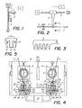
- FIG. 1 shows a portion of wire F, one end of which is fixed at P and the other end of which carries a weight M of approximately 5 to 10 g.
- the thread Under the action of the latter the thread will become untwisted. If it is a thread obtained on a slider ring loom, the weight M will fall after a certain number of turns carrying with it the untwisted fibers which are not retained in P. On the other hand, if it s is a yarn obtained by the "open-end" spinning process, all the fibers will not participate in the untwisting since some of them did not participate directly in the average twist of the yarn, so that the weight M will be retained by these fibers and will not fall.
- FIG 1 shows, in addition, a vibrating blade L fixed on a support so that it is close to and parallel to the wire.
- An electromagnet E supplied with current pulses by a generator G, is arranged so as to make the blade L vibrate.
- vibrations are communicated to the fibers of the wire F, which will have the consequence the reduction of their coefficient of friction and their dislocation, so that all the fibers not retained in P will separate under the action of the weight M and this one will fall after a certain time as far as the frequencies of the blade L and the pendulum system formed by the wire F and the weight M are different and non-harmonic.
- the frequency of the blade L is 100 Hz and the separation of the fibers, under the action of the weight M, occurs in a few seconds.
- the free end of the wire F a bundle consisting of all the fibers retained at P, the length of which corresponds substantially to the average length of the fibers. This is an important factor in obtaining good bonding of the wire.
- the device represented in FIG. 2 comprises a comb C associated with a sonotrode S connected, by a transducer T, to a pulse generator G.
- the transducer T is associated with a worm screw V driven by a motor D.
- the vibrations reducing the coefficient of friction of the fibers cause the dislocation of the latter and facilitate the progression of the teeth of the comb C.
- the son is undone and the fibers not retained in P are separated and eliminated.
- the vibrating member is driven pneumatically, the pressurized air being widely available in the textile industry and the range of frequencies then depending only on the natural frequency of the vibrating member which can be sized accordingly.
- the energy transmitted to the wire can be greater than the energy developed in the device described above.
- FIG. 4 The apparatus illustrated in FIG. 4 is essentially that shown and described in the specification of Swiss patent No ... (patent application 6379/78) to which reference may be made for more details, given that this description will be limited to the elements necessary for understanding the invention.
- This device essentially comprises two pins 1 and 2 mounted rotatably each in a support 3 and 4 respectively, mounted oscillating in a frame 5 along an axis orthogonal to that of the spindle.
- Each of these pins 1 and 2 ends at one of its ends with a circular head 6, respectively 7, split radially 6a, respectively 7a, to allow the wire F to engage in this circular head 6, respectively 7 and s 'wrap around pin 1, respectively 2.
- the supports 3 and 4 are likely to occupy two positions each, one in which the pins 1 and 2 are coaxial and the other in which they are parallel one to the other. In this latter position, shown in FIG. 4, each of pins 1 and 2 is located opposite the end of a duct 8, respectively 9, connected to a source of air suction 10.
- each of the conduits is formed of two parts 11a and 11b, respectively 12a and 12b, which extend substantially longitudinally in the conduit. These two parts are fixed to each other, for example by means of screws 13 (fig. 5).
- a flexible flapping element constituted by a tongue 14, respectively 15, integral with a fixing lug 16, respectively .17 clamped between said parts end 11a and 11b, respectively 12a and 12b and forming with the respective tongue a T.
- These beat elements are preferably cut from a rubber membrane about 0.25 mm thick.
- Each of the tongues 14 and 15 is preferably located near the longitudinal axis of the respective conduit in order to be able to float freely therein.
- the section of these conduits 8 and 9, at least in their part in which the tongue 14, respectively 15, extends, is preferably square or rectangular so that the free end of the tongue can beat against two opposite walls of the drove.
- a comb 18 and 19 respectively is fixed.
- a pair of scissors formed of two steel blades 22 and 23, one of which 22 is slidably mounted relative to the other 23 and each of which has an opening 24 and 25 respectively, is arranged transversely to each of the suction conduits 8 and 9.
- each of them is introduced into one of the conduits 8 and 9 in which there is a slight depression created by the suction source 10.
- the pins 1 and 2 are rotated in opposite directions, so that on each of them a portion of respective wire is wound because of its engagement in the slot 6a, respectively 7a, formed in the head 6, respectively 7, of spindle 1, respectively 2.
- elbow formed in each conduit 8 and 9 below the scissors 22, 23, allows, during the winding of the wire on each of the pins 1 and 2, to induce a certain distortion of the wire in the portion between the spit and the elbow.
- the direction of twist of the fibers in this portion must be opposite to the direction of rotation of the spindle.
- each of the two assemblies associated with the connecting device and formed of a conduit 8, respectively 9, open at both ends, of a flexible beat element 14, respectively 15, and of a source d air suction constitutes a device implementing the method according to the present invention.
- this device makes it possible to undo the wires which hitherto could not have been under the sole effect of the means normally included in such a reattachment device, that is to say by means of the combs 18 and 19 and air flow in conduits 8 and 9.
- the wire is defeated in a time not exceeding one second. It is obvious that this device is far more efficient than the two devices shown in FIGS. 1 and 2 respectively. It is much more reliable, much simpler to carry out and makes it possible to reduce the duration of the operation.
- Figures 6 and 7 illustrate another embodiment of the pneumatic device associated with a connecting device which is the subject of Swiss patent No .... (patent application No 10448/79) to which we can refer to obtain more details on the actual piecing.
- Figs. 6 and 7 illustrate only one of the two oscillating supports 28, carrying a spindle 29 rotatably mounted about an axis orthogonal to that of oscillation of the support 28 and provided with a head 29a slotted ra dialement.
- the other support, not shown, is perfectly similar to support 28 and is not necessary for understanding the invention since the operation of undoing the ends of the wire to be attached is carried out symmetrically on the two supports.
- the support 28 is integral with a tubular shaft 30 to which is fixed a radial arm 31 connected to the rod of a drive piston 32.
- An arm 33 one end of which carries a bevel gear 34, passes through the tubular shaft 30 This pinion 34 is engaged with a second bevel gear 35 wedged on the shaft of the spindle 29.
- a plate 36 having essentially a channel 37 and a distribution chamber 40 into which opens an intake duct 38 connected to a pressurized air source 39 is fixed on the support 28.
- the distribution chamber 40 has a nozzle 41 at the level of the channel 37, formed by a lip 42 forming a flow along the surface of this channel.
- a bypass conduit 43 connects the chamber 40 to a bore 44 in which is fixed a cone 45 whose apex is adjacent to the bottom of the channel 37 and whose axis of revolution is perpendicular to the bypass conduit 43.
- a second tubular shaft 46 connected to the rod of a jack 47 by a radial arm 48, is pivotally mounted around the tubular shaft 30, as well as through a frame 49.
- This tubular shaft 46 is integral with a second radial arm 50 at the end of which is pivoted a fixing rod 51 connected to a frame 52.
- a second fixing rod 53, fixed to the same frame 52 is pivoted through an arm 54 parallel to the radial arm 50 and articulated to the end of another radial arm 55 secured to the tubular shaft 30, so as to form a deformable parallelogram, carrying the frame 52.
- the frame 52 carries a natural rubber membrane 56 of about 0.25 mm thick, which has a longitudinal slot 56a and two transverse slots 56b delimiting two tabs 56c whose longitudinal ends are adjacent.
- This frame 52 is capable of occupying two positions relative to the support 28, controlled by the jack 47. In one of these positions, the frame 52 is adjacent to the plate 36 and its channel 37, in the other, shown in lines mixed with, fig. 6, it is excluded.
- Two suction tubes 57 and 58, connected to a suction source 59 are arranged on either side of the oscillating support 28 and its plate 36, when the support is in the position shown in FIG. 6. These tubes serve to tension the wire F through the plate 36 while the frame 52 is spaced from this plate and to pass it against the edge of the slotted head 29a of the pin 29.
- the pin 29 is entrained in rotation using the shaft 33 and the pinions 34 and 35.
- the wire F enters the slot of the head 29a and is wound around the spindle 29.
- the direction of rotation of the spindle is chosen so as to untwist the portion of wire between the head 29a and the suction tube 58, as explained in detail in the aforementioned Swiss patent.
- the frame 52 carrying the membrane 56 is brought, by virtue of its carrying system with deformable parallelogram 50, 54 and 55, against the plate 36, so that the membrane 56 covers the wire located in channel 37.
- Pressurized air is then sent to the distribution chamber 40 and from this into the channel 37.
- the air flow passing through the channel vibrates the tabs 56c which beat the wire which is at the same time subjected to a tensile force due to the friction of the air current.
- the yarn breaks completely and the fibers not retained by the spindle 29 are separated and eliminated by the air stream.
- the device according to the invention incorporated in the connecting device, is formed from the channel 37, the membrane 56 with its tongues 56c, and the source of pressurized air (with the conduits connecting it to the channel 37).
- the vibrating elements 56c driven in vibration by the air current, have been dimensioned to vibrate at frequencies of the order of 500 to 2000 Hz. It has been observed that it is in this frequency range with elements made of a material as flexible as rubber of the order of 0.2 to 0.3 mm thick capable of vibrating, at these frequencies, at amplitudes of the order of a millimeter, as the results are the best.
Landscapes
- Engineering & Computer Science (AREA)
- Mechanical Engineering (AREA)
- Textile Engineering (AREA)
- Spinning Or Twisting Of Yarns (AREA)
- Yarns And Mechanical Finishing Of Yarns Or Ropes (AREA)
- Treatment Of Fiber Materials (AREA)
- Replacing, Conveying, And Pick-Finding For Filamentary Materials (AREA)
- Coating With Molten Metal (AREA)
- Preliminary Treatment Of Fibers (AREA)
Priority Applications (1)
| Application Number | Priority Date | Filing Date | Title |
|---|---|---|---|
| AT81810435T ATE15787T1 (de) | 1980-11-24 | 1981-10-30 | Vorrichtung zum aufdrehen einer laenge eines textilgarnes und vorrichtung zur anwendung dieses verfahrens. |
Applications Claiming Priority (2)
| Application Number | Priority Date | Filing Date | Title |
|---|---|---|---|
| CH8646/80 | 1980-11-24 | ||
| CH864680 | 1980-11-24 |
Publications (2)
| Publication Number | Publication Date |
|---|---|
| EP0053093A1 true EP0053093A1 (de) | 1982-06-02 |
| EP0053093B1 EP0053093B1 (de) | 1985-09-25 |
Family
ID=4343043
Family Applications (1)
| Application Number | Title | Priority Date | Filing Date |
|---|---|---|---|
| EP81810435A Expired EP0053093B1 (de) | 1980-11-24 | 1981-10-30 | Vorrichtung zum Aufdrehen einer Länge eines Textilgarnes und Vorrichtung zur Anwendung dieses Verfahrens |
Country Status (14)
| Country | Link |
|---|---|
| US (1) | US4406115A (de) |
| EP (1) | EP0053093B1 (de) |
| JP (1) | JPS57117470A (de) |
| KR (1) | KR830007906A (de) |
| AT (1) | ATE15787T1 (de) |
| AU (1) | AU541593B1 (de) |
| BR (1) | BR8107499A (de) |
| CA (1) | CA1179492A (de) |
| DD (1) | DD201705A5 (de) |
| DE (1) | DE3172449D1 (de) |
| ES (1) | ES507375A0 (de) |
| IN (1) | IN155570B (de) |
| SU (1) | SU1123541A3 (de) |
| ZA (1) | ZA818085B (de) |
Cited By (3)
| Publication number | Priority date | Publication date | Assignee | Title |
|---|---|---|---|---|
| DE3400233A1 (de) * | 1983-01-07 | 1984-07-12 | Elitex, koncern textilního strojírenství, Liberec | Verfahren zum spleissen von faserigen gebilden, insbesondere von garnen, und vorrichtung zur durchfuehrung dieses verfahrens auf textilmaschinen |
| US4888943A (en) * | 1987-02-20 | 1989-12-26 | Mesdan S.P.A. | Apparatus for loosening and unravelling a yarn |
| US5167111A (en) * | 1987-07-15 | 1992-12-01 | Mesdan S.P.A. | Universal method to untwist, unravel and open up a textile yarn |
Families Citing this family (9)
| Publication number | Priority date | Publication date | Assignee | Title |
|---|---|---|---|---|
| DE3151270A1 (de) * | 1981-12-24 | 1983-07-07 | W. Schlafhorst & Co, 4050 Mönchengladbach | Verfahren und vorrichtung zum knotenfreien verbinden zweier faeden |
| JPS5939662A (ja) * | 1982-08-27 | 1984-03-05 | Teijin Seiki Co Ltd | 糸条の結合装置 |
| IT1218731B (it) * | 1983-08-05 | 1990-04-19 | Savio Spa | Perfezionamenti al procedimento di giunzione meccanica di fili tessili, nonche' dispositivo adottante tali perfezionamenti |
| EP0162367B2 (de) * | 1984-05-19 | 1993-08-04 | Rieter Ingolstadt Spinnereimaschinenbau AG | Verfahren und Vorrichtung zum Vorbereiten eines abgelängten Fadenendes zum Wiederanspinnen einer Offenend-Spinnvorichtung |
| DE3607206C2 (de) * | 1986-03-05 | 1996-10-31 | Schlafhorst & Co W | Verfahren und Vorrichtung zum Herstellen einer Spleißverbindung |
| ES2021390B3 (es) * | 1986-06-11 | 1991-11-01 | Carlos Pujol-Isern | Procedimiento y dispositivo para anudar dos hilos textiles. |
| DE4222662B4 (de) * | 1992-07-10 | 2005-12-08 | Saurer Gmbh & Co. Kg | Vorrichtung zum Vorbereiten von Fadenenden |
| FR3037271B1 (fr) * | 2015-06-12 | 2018-01-12 | Centre Technique Des Industries Mecaniques | Installation de decoupe de couche mince de materiau synthetique |
| JP6601229B2 (ja) | 2016-01-15 | 2019-11-06 | 信越化学工業株式会社 | オルガノポリシロキサン乳化組成物及び樹脂組成物 |
Citations (4)
| Publication number | Priority date | Publication date | Assignee | Title |
|---|---|---|---|---|
| FR1129480A (fr) * | 1954-03-15 | 1957-01-22 | Eastman Kodak Co | Procédé et machine d'ouvraison d'une mèche de filaments continus crêpés |
| US3378429A (en) * | 1965-01-04 | 1968-04-16 | Branson Instr | Method and apparatus for treating material with sonic energy |
| DE2350843A1 (de) * | 1973-10-10 | 1975-04-24 | Fritz Stahlecker | Vorrichtung zum anspinnen eines fadens bei einem offen-end-spinnaggregat |
| DE2350844A1 (de) * | 1973-10-10 | 1975-04-24 | Fritz Stahlecker | Vorrichtung zum anspinnen eines fadens bei einem offen-end-spinnaggregat |
Family Cites Families (6)
| Publication number | Priority date | Publication date | Assignee | Title |
|---|---|---|---|---|
| US2515172A (en) * | 1948-04-30 | 1950-07-18 | Abbott Machine Co | Splicing threads |
| SE406755B (sv) * | 1973-01-19 | 1979-02-26 | Pujol Isern Carlos | Sett for skarvning av tradar och forgarn i textilprocesser samt anordning for genomforande av settet |
| JPS5343218A (en) * | 1976-09-30 | 1978-04-19 | Ishikawajima Kenzai Kogyo Kk | Underground tank construction method |
| US4229935A (en) * | 1978-03-21 | 1980-10-28 | Wain John K | Joining yarns |
| CH623290A5 (de) | 1978-06-12 | 1981-05-29 | Fomento Inversiones Ind | |
| JPS55101560A (en) * | 1979-01-23 | 1980-08-02 | Murata Mach Ltd | Method and apparatus for joining spum yarns |
-
1981
- 1981-10-30 AT AT81810435T patent/ATE15787T1/de not_active IP Right Cessation
- 1981-10-30 EP EP81810435A patent/EP0053093B1/de not_active Expired
- 1981-10-30 DE DE8181810435T patent/DE3172449D1/de not_active Expired
- 1981-11-10 US US06/320,098 patent/US4406115A/en not_active Expired - Lifetime
- 1981-11-18 BR BR8107499A patent/BR8107499A/pt unknown
- 1981-11-18 CA CA000390313A patent/CA1179492A/fr not_active Expired
- 1981-11-19 DD DD81234986A patent/DD201705A5/de unknown
- 1981-11-20 ZA ZA818085A patent/ZA818085B/xx unknown
- 1981-11-20 SU SU813357208A patent/SU1123541A3/ru active
- 1981-11-20 AU AU77679/81A patent/AU541593B1/en not_active Ceased
- 1981-11-21 IN IN1300/CAL/81A patent/IN155570B/en unknown
- 1981-11-21 JP JP56186146A patent/JPS57117470A/ja active Granted
- 1981-11-23 ES ES507375A patent/ES507375A0/es active Granted
- 1981-11-24 KR KR1019810004546A patent/KR830007906A/ko not_active Withdrawn
Patent Citations (4)
| Publication number | Priority date | Publication date | Assignee | Title |
|---|---|---|---|---|
| FR1129480A (fr) * | 1954-03-15 | 1957-01-22 | Eastman Kodak Co | Procédé et machine d'ouvraison d'une mèche de filaments continus crêpés |
| US3378429A (en) * | 1965-01-04 | 1968-04-16 | Branson Instr | Method and apparatus for treating material with sonic energy |
| DE2350843A1 (de) * | 1973-10-10 | 1975-04-24 | Fritz Stahlecker | Vorrichtung zum anspinnen eines fadens bei einem offen-end-spinnaggregat |
| DE2350844A1 (de) * | 1973-10-10 | 1975-04-24 | Fritz Stahlecker | Vorrichtung zum anspinnen eines fadens bei einem offen-end-spinnaggregat |
Cited By (5)
| Publication number | Priority date | Publication date | Assignee | Title |
|---|---|---|---|---|
| DE3400233A1 (de) * | 1983-01-07 | 1984-07-12 | Elitex, koncern textilního strojírenství, Liberec | Verfahren zum spleissen von faserigen gebilden, insbesondere von garnen, und vorrichtung zur durchfuehrung dieses verfahrens auf textilmaschinen |
| US4888943A (en) * | 1987-02-20 | 1989-12-26 | Mesdan S.P.A. | Apparatus for loosening and unravelling a yarn |
| US4890451A (en) * | 1987-02-20 | 1990-01-02 | Mesdan S.P.A. | Method for loosening and unravelling a textile yarn |
| US5167111A (en) * | 1987-07-15 | 1992-12-01 | Mesdan S.P.A. | Universal method to untwist, unravel and open up a textile yarn |
| US5289673A (en) * | 1987-07-15 | 1994-03-01 | Mesdan S.P.A. | Device to untwist, unravel and open up a textile yarn |
Also Published As
| Publication number | Publication date |
|---|---|
| DD201705A5 (de) | 1983-08-03 |
| KR830007906A (ko) | 1983-11-07 |
| BR8107499A (pt) | 1982-08-10 |
| SU1123541A3 (ru) | 1984-11-07 |
| CA1179492A (fr) | 1984-12-18 |
| ES8304623A1 (es) | 1983-03-01 |
| ATE15787T1 (de) | 1985-10-15 |
| ES507375A0 (es) | 1983-03-01 |
| AU541593B1 (en) | 1985-01-10 |
| US4406115A (en) | 1983-09-27 |
| IN155570B (de) | 1985-02-16 |
| JPS633820B2 (de) | 1988-01-26 |
| EP0053093B1 (de) | 1985-09-25 |
| ZA818085B (en) | 1982-10-27 |
| DE3172449D1 (en) | 1985-10-31 |
| JPS57117470A (en) | 1982-07-21 |
Similar Documents
| Publication | Publication Date | Title |
|---|---|---|
| EP0053093B1 (de) | Vorrichtung zum Aufdrehen einer Länge eines Textilgarnes und Vorrichtung zur Anwendung dieses Verfahrens | |
| EP0595373B1 (de) | Zahnreinigungsvorrichtung mit interdentalem Seidenfaden | |
| FR2546148A1 (fr) | Dispositif d'epissure pour files | |
| FR2497240A1 (fr) | Dispositif a buse mobile pour insertion pneumatique de la trame sur une machine a tisser sans navette | |
| CH623290A5 (de) | ||
| EP0029808B1 (de) | Verfahren zum Verbinden von zwei Fadenenden und Vorrichtung zur Durchführung dieses Verfahrens | |
| FR2545803A1 (fr) | Dispositif d'epissure de fils pour files | |
| CH644909A5 (fr) | Dispositif de formation d'une reserve de fil pour metiers a tisser. | |
| CH692584A5 (fr) | Unité de filage à extrémité ouverte du type à rotor et procédé de mise en action de cette unité. | |
| EP0371919A1 (de) | Nähmaschine | |
| FR2521538A1 (fr) | Procede de prevention de la detorsion irreguliere des extremites de fil dans le raccordement de fils multifibres | |
| CH659488A5 (fr) | Procede et dispositif pour produire des fils guipes. | |
| EP1254976A1 (de) | Verfahren zum kämmen und geradlinige Kämmmaschine dafür | |
| CH616829A5 (en) | automatic machine for making a clove hitch with a cord around an object and use of the machine | |
| EP1114578B1 (de) | Gerät zum Anbinden eines oder mehrerer Objekte, wie z.B. Rebtriebe | |
| CH619374A5 (en) | Fibre bundle | |
| FR2545108A1 (fr) | Procede de filature et dispositif pour la mise en oeuvre de ce procede | |
| FR2480799A1 (fr) | Procede et dispositif pour la filature de fibres textiles liberees | |
| FR2474071A1 (fr) | Procede de fabrication des pompons, des moyens de mise en oeuvre de ce procede et les produits obtenus | |
| FR2538008A1 (fr) | Dispositif pour l'insertion d'un fil de trame dans la foule d'un metier a tisser | |
| FR2646587A1 (fr) | Machine pour l'egrenage du lin | |
| FR3062286B3 (fr) | Dispositif pour depouiller des agneaux | |
| EP0249578A1 (de) | Verfahren und Vorrichtung zum Verbinden von zwei Fäden | |
| BE707501A (de) | ||
| FR2652592A1 (fr) | Procede et appareillage de filage en fausse torsion. |
Legal Events
| Date | Code | Title | Description |
|---|---|---|---|
| PUAI | Public reference made under article 153(3) epc to a published international application that has entered the european phase |
Free format text: ORIGINAL CODE: 0009012 |
|
| AK | Designated contracting states |
Designated state(s): AT BE CH DE FR GB IT |
|
| 17P | Request for examination filed |
Effective date: 19821119 |
|
| ITF | It: translation for a ep patent filed | ||
| RAP1 | Party data changed (applicant data changed or rights of an application transferred) |
Owner name: MESDAN S.P.A. Owner name: SCHWEITER MASCHINENFABRIK A.G. |
|
| GRAA | (expected) grant |
Free format text: ORIGINAL CODE: 0009210 |
|
| AK | Designated contracting states |
Designated state(s): AT BE CH DE FR GB IT LI |
|
| PG25 | Lapsed in a contracting state [announced via postgrant information from national office to epo] |
Ref country code: AT Effective date: 19850925 |
|
| REF | Corresponds to: |
Ref document number: 15787 Country of ref document: AT Date of ref document: 19851015 Kind code of ref document: T |
|
| PG25 | Lapsed in a contracting state [announced via postgrant information from national office to epo] |
Ref country code: BE Effective date: 19851031 |
|
| REF | Corresponds to: |
Ref document number: 3172449 Country of ref document: DE Date of ref document: 19851031 |
|
| BERE | Be: lapsed |
Owner name: MESDAN S.P.A. Effective date: 19851031 Owner name: SCHWEITER MASCHINENFABRIK A.G. Effective date: 19851031 |
|
| PLBI | Opposition filed |
Free format text: ORIGINAL CODE: 0009260 |
|
| 26 | Opposition filed |
Opponent name: W. SCHLAFHORST & CO. Effective date: 19860621 |
|
| PLBN | Opposition rejected |
Free format text: ORIGINAL CODE: 0009273 |
|
| STAA | Information on the status of an ep patent application or granted ep patent |
Free format text: STATUS: OPPOSITION REJECTED |
|
| 27O | Opposition rejected |
Effective date: 19880416 |
|
| ITTA | It: last paid annual fee | ||
| PGFP | Annual fee paid to national office [announced via postgrant information from national office to epo] |
Ref country code: GB Payment date: 19941026 Year of fee payment: 14 |
|
| PGFP | Annual fee paid to national office [announced via postgrant information from national office to epo] |
Ref country code: FR Payment date: 19941031 Year of fee payment: 14 |
|
| PGFP | Annual fee paid to national office [announced via postgrant information from national office to epo] |
Ref country code: CH Payment date: 19950127 Year of fee payment: 14 |
|
| PG25 | Lapsed in a contracting state [announced via postgrant information from national office to epo] |
Ref country code: GB Effective date: 19951030 |
|
| PG25 | Lapsed in a contracting state [announced via postgrant information from national office to epo] |
Ref country code: LI Effective date: 19951031 Ref country code: CH Effective date: 19951031 |
|
| REG | Reference to a national code |
Ref country code: CH Ref legal event code: PL |
|
| GBPC | Gb: european patent ceased through non-payment of renewal fee |
Effective date: 19951030 |
|
| PG25 | Lapsed in a contracting state [announced via postgrant information from national office to epo] |
Ref country code: FR Effective date: 19960628 |
|
| REG | Reference to a national code |
Ref country code: FR Ref legal event code: ST |
|
| PGFP | Annual fee paid to national office [announced via postgrant information from national office to epo] |
Ref country code: DE Payment date: 19971110 Year of fee payment: 17 |
|
| PG25 | Lapsed in a contracting state [announced via postgrant information from national office to epo] |
Ref country code: DE Free format text: LAPSE BECAUSE OF NON-PAYMENT OF DUE FEES Effective date: 19990803 |