EP0053191A1 - Reinigungsvorrichtung für tonbandköpfe - Google Patents
Reinigungsvorrichtung für tonbandköpfe Download PDFInfo
- Publication number
- EP0053191A1 EP0053191A1 EP19810901673 EP81901673A EP0053191A1 EP 0053191 A1 EP0053191 A1 EP 0053191A1 EP 19810901673 EP19810901673 EP 19810901673 EP 81901673 A EP81901673 A EP 81901673A EP 0053191 A1 EP0053191 A1 EP 0053191A1
- Authority
- EP
- European Patent Office
- Prior art keywords
- tape
- cleaning device
- strands
- adhesive
- cleaning
- Prior art date
- Legal status (The legal status is an assumption and is not a legal conclusion. Google has not performed a legal analysis and makes no representation as to the accuracy of the status listed.)
- Withdrawn
Links
- 238000004140 cleaning Methods 0.000 title claims abstract description 55
- 239000000853 adhesive Substances 0.000 claims description 31
- 230000001070 adhesive effect Effects 0.000 claims description 31
- 239000004744 fabric Substances 0.000 claims description 24
- 230000002463 transducing effect Effects 0.000 claims description 24
- 239000000463 material Substances 0.000 claims description 12
- 125000006850 spacer group Chemical group 0.000 claims description 5
- 239000010410 layer Substances 0.000 abstract description 11
- 229920002799 BoPET Polymers 0.000 abstract description 8
- 239000012790 adhesive layer Substances 0.000 abstract description 7
- 239000005041 Mylar™ Substances 0.000 abstract description 6
- 229920004934 Dacron® Polymers 0.000 abstract description 4
- 239000005020 polyethylene terephthalate Substances 0.000 abstract description 4
- 239000006247 magnetic powder Substances 0.000 abstract 1
- 239000006249 magnetic particle Substances 0.000 description 9
- 239000012530 fluid Substances 0.000 description 7
- 239000002904 solvent Substances 0.000 description 3
- 238000003860 storage Methods 0.000 description 3
- 239000003522 acrylic cement Substances 0.000 description 2
- 229910003460 diamond Inorganic materials 0.000 description 2
- 239000010432 diamond Substances 0.000 description 2
- 238000000034 method Methods 0.000 description 2
- 239000004677 Nylon Substances 0.000 description 1
- 238000005299 abrasion Methods 0.000 description 1
- NIXOWILDQLNWCW-UHFFFAOYSA-N acrylic acid group Chemical group C(C=C)(=O)O NIXOWILDQLNWCW-UHFFFAOYSA-N 0.000 description 1
- 239000012298 atmosphere Substances 0.000 description 1
- 239000003795 chemical substances by application Substances 0.000 description 1
- 239000011538 cleaning material Substances 0.000 description 1
- 230000008602 contraction Effects 0.000 description 1
- 238000000151 deposition Methods 0.000 description 1
- 230000006866 deterioration Effects 0.000 description 1
- 238000004519 manufacturing process Methods 0.000 description 1
- 229920001778 nylon Polymers 0.000 description 1
- 239000004033 plastic Substances 0.000 description 1
Images

Classifications
-
- G—PHYSICS
- G11—INFORMATION STORAGE
- G11B—INFORMATION STORAGE BASED ON RELATIVE MOVEMENT BETWEEN RECORD CARRIER AND TRANSDUCER
- G11B5/00—Recording by magnetisation or demagnetisation of a record carrier; Reproducing by magnetic means; Record carriers therefor
- G11B5/41—Cleaning of heads
-
- G—PHYSICS
- G11—INFORMATION STORAGE
- G11B—INFORMATION STORAGE BASED ON RELATIVE MOVEMENT BETWEEN RECORD CARRIER AND TRANSDUCER
- G11B23/00—Record carriers not specific to the method of recording or reproducing; Accessories, e.g. containers, specially adapted for co-operation with the recording or reproducing apparatus ; Intermediate mediums; Apparatus or processes specially adapted for their manufacture
- G11B23/02—Containers; Storing means both adapted to cooperate with the recording or reproducing means
- G11B23/04—Magazines; Cassettes for webs or filaments
- G11B23/049—Cassettes for special applications not otherwise provided for
Definitions
- the present invention relates to a cleaning device for contact-type information transducing heads, such as for magnetic read or write heads, for example.
- this invention relates to 'such a cleaning device which can be used without solvents or other fluids, and which collects material removed from transducing heads.
- contact-type transducing heads such as read or write heads in a magnetic tape player
- undesired materials on the contact surface of a transducing head can greatly reduce the precision and accuracy with which the transducing head operates. For example, magnetic particles that have become dislodged from a magnetic recording medium as it runs on the contact surface of a magnetic transducing head and have adhered to the head can cause significant deterioration in the performance of the magnetic transducer head.
- a first approach utilizes fluids to remove undesired deposits from the transducing heads chemically.
- a second approach utilizes a tape, such as a hard flat tape or a tape provided with a abrasive surface, which is run on the contact surface of the transducing head to remove magnetic particles attached to the head.
- the present invention is directed to an improved cleaning device adapted for use with transducing heads, which to a large extent overcomes the foregoing disadvantages of the prior art.
- the cleaning device of this application is well suited for use with contact-type transducing heads, such as magnetic recording -or playback heads, for example.
- a cleaning device for a contact-type information transducing head which comprises a base, means for defining a plurality of raised areas projecting away from at least one surface of the base, and an adhesive deposited on the at least one surface of the base between the plurality of raised areas.
- the adhesive deposited on the base between the raised areas acts to capture material removed from a transducing head by the raised areas.
- materials such as magnetic particles removed from tape heads can be controlled and substantially prevented from depositing on other portions of the information recording or reading system.
- this invention can operate entirely without the need for fluids to remove deposits from the transducing head chemically.
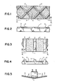
- FIGS. 1 and 2 show a top view of a tape of a first preferred embodiment of the invention.
- This tape includes an elongated base 1 into which is stamped a raised spacer pattern which defines a pattern of raised areas.
- the raised areas of this embodiment are arranged in a diamond pattern as a plurality of intersecting ridges 3.
- each of the ridges 3 is substantially triangular in cross-section.
- a layer of adhesive 2 is deposited on the base 1 between the raised ridges 3 such that the adhesive 2 substantially fills the area between the ridges 3.
- the uppermost portions of the ridges 3 are preferably not covered with adhesive.
- FIGS. 3 and 4 show a tape of a second preferred embodiment of this invention which also includes an elongated base 1.
- This base 1 defines a plurality of parallel ridges 3 extending across the width of the base 1.
- a layer of adhesive 2 is deposited on the base 1 between the ridges 3.
- the uppermost portions of the ridges 3 extend away from the layer of adhesive 2 and are preferably not covered by adhesive.
- the parallel ridges 3 of FIGS. 3 and 4 are spaced and parallel, similar to the wooden teeth of Japanese clogs.
- FIG. 5 shows a schematic representation of the first preferred embodiment of FIGS. 1 and 2 in operation.
- the uppermost portions of the ridges 3 rub across the contacting surface of a transducing-head 4.
- This transducing head 4 can for example be a read head or a write head in a magnetic tape player or recorder.
- the ridges 3 serve to remove magnetic particles attached to the head 4. These removed magnetic particles are captured by the adhesive 2 and are thereby prevented from dispersing throughout the system of which the head 4 is a part.
- the cleaning device of this invention is easy to use, does not require the use of cleaning fluids, and substantially prevents the _scattering or dispersal of magnetic particles removed from the head 4.
- a third preferred embodiment of the present invention employs a base 1 formed of a mylar tape.
- an adhesive 2 is an organic, low-tack adhesive which is sprayed onto one entire surface of the mylar base 1.
- Overlying portions of the adhesive layer 2 is a layer of open weave fabric 9. As shown in FIG. 7, this layer of fabric 9 is formed of a plurality of spaced strands 5 which are held in place on the mylar base 1 by means of the adhesive 2.
- the adhesive 2 thus serves to bond individual strands 5 in place securely and to provide positive support to the strands 5 during the cleaning operation.
- this fabric 9 is formed of a plastic material such as dacron. Other fabrics such as acrylic or nylon fabrics may be used in alternate embodiments of this invention. In all cases, however, the fabric 9 should be made of a material which is softer than the surface of the transducing head to be cleaned. In this way undesirable abrasion and wear of the transducing head are minimized.
- the fabric 9 is a coarse weave fabric which allows a major portion of the layer of adhesive 2 to be exposed between adjacent strands 5.
- the adhesive layer 2 is then sprayed on the tape while dissolved in a volatile solvent such that the adhesive layer remains after the solvent has evaporated.
- the fabric 9 is then pressed onto the adhesive layer 2 in order to bond the fabric 9 to the tape by means of the adhesive 2.
- the tape is then slit longitudinally into pieces of the desired width.
- the finished width of the base 1 should be equal to that of the recording tape normally used in the equipment to be cleaned.
- the mylar base 1 is .061 mm in thickness and the finished base 1 is 3.81 mm in width.
- Each of the strands 5 is formed of two twisted pairs of monofilaments 5', each of which is formed of dacron.
- the overall thickness of the fabric 9 is about .094 mm and the thickness of individual strands 5 is about .033 - .038 mm.
- the average spacing between centers of adjacent strands 5 along the length of the base 1 is .25 mm and the average spacing between adjacent strands 5 across the width of the base 1 is about .25 mm.
- the adhesive 2 is a low tack organic adhesive which preferentially bonds to mylar more securely than to any other material with which it is likely to come into contact in use. In this way the adhesive 2 is prevented from pulling off onto the contact surface of the head 4.
- Adhesive suitable to be used in this invention include a special acrylic adhesive agent available from Nitto Denki Kogyo K.K. in Baraki-shi, Ohsaka-fu, Japan, which acrylic adhesive has the characteristics that its adhesiveness is not lost even if it be exposed to the air atmosphere for a long time.
- FIG. 8 shows a tape of a fourth preferred embodiment which utilizes a base 1 and a layer of adhesive 2 similar to the corresponding elements of the embodiment of FIGS. 6-7.
- This fourth embodiment includes a hexagonal weave fabric 10 which is formed of strands 8, each of which is in turn formed of a twisted pair of dacron monofilaments about .36 mm in diameter.
- the hexagonal cells of the fabric 10 define internal angles of 48° and 156°, the dimensions of individual hexagonal cells are .86 mm across the width of the base 1 and 1.8 mm along the length of the base 1.
- the embodiment of FIG. 8 is assembled in a manner similar to that described above in connection with FIGS. 6-7.
- any one of the four embodiments described above can be installed in a standard cassette of the type shown in FIG. 9.
- a cassette includes a cassette housing 6 and two hubs 7 mounted for rotation in the housing 6.
- the cleaning device of this invention can be readily and conveniently used in the same manner as a conventional magnetic tape cassette.
- the cassette 6 is simply installed in a tape player and the tape player controls are operated to cause the -base 1 to be moved across the recording and playback transducer heads.
- the length of the base 1 is adquate to provide fifteen seconds of "play" at a tape transport speed of 1-7/8 inch per second. In this way the transducer heads can readily be cleaned without special procedures or tools.
- the present invention is not limited to use with any particular contact-type transducer head.
- this invention can be used both with magnetic transducer heads (such as those used in audio tape systems, video tape systems, and computer storage tape systems, for example) as well as with other types of contact-type transducer heads (such as capacitance sensing transducer heads of the type used with one type of video disc).
- the present invention is not limited to use with tape type storage media, but can readily be adapted for use with other types of storage media such as discs, drums, and the like.
- a raised pattern of ridges on both sides of a cleaning device such as a tape in order to clean other components, such as pinch rollers, simultaneously with the cleaning of transducer heads.
- the pattern of raised areas may be built up of disconnected regions rather than ridges or strands.
- the dimensions and materials described above can readily be altered if desired.
Landscapes
- Manufacturing Of Magnetic Record Carriers (AREA)
- Cleaning In General (AREA)
Applications Claiming Priority (2)
| Application Number | Priority Date | Filing Date | Title |
|---|---|---|---|
| JP8076980U JPS634254Y2 (de) | 1980-06-10 | 1980-06-10 | |
| JP80769/80U | 1980-06-10 |
Publications (2)
| Publication Number | Publication Date |
|---|---|
| EP0053191A1 true EP0053191A1 (de) | 1982-06-09 |
| EP0053191A4 EP0053191A4 (de) | 1982-10-14 |
Family
ID=13727619
Family Applications (1)
| Application Number | Title | Priority Date | Filing Date |
|---|---|---|---|
| EP19810901673 Withdrawn EP0053191A4 (de) | 1980-06-10 | 1981-06-10 | Reinigungsvorrichtung für tonbandköpfe. |
Country Status (9)
| Country | Link |
|---|---|
| EP (1) | EP0053191A4 (de) |
| JP (1) | JPS634254Y2 (de) |
| AU (1) | AU7293281A (de) |
| DE (1) | DE3152104A1 (de) |
| DK (1) | DK52782A (de) |
| GB (1) | GB2090460B (de) |
| NL (1) | NL8120199A (de) |
| SE (1) | SE8200710L (de) |
| WO (1) | WO1981003711A1 (de) |
Cited By (2)
| Publication number | Priority date | Publication date | Assignee | Title |
|---|---|---|---|---|
| FR2557343A1 (fr) * | 1983-12-23 | 1985-06-28 | Allsop Inc | Dispositif pour nettoyer un appareil d'enregistrement et de lecture tel qu'un magnetoscope |
| WO1997010596A3 (en) * | 1995-09-14 | 1997-05-15 | Joseph Frederick Fritsch | A cleaning device for cleaning components of a video unit |
Family Cites Families (4)
| Publication number | Priority date | Publication date | Assignee | Title |
|---|---|---|---|---|
| JPS512597Y1 (de) * | 1970-09-18 | 1976-01-26 | ||
| US3810230A (en) * | 1972-01-12 | 1974-05-07 | Ampex | Demagnetizer and cleaning cartridge |
| JPS526262Y2 (de) * | 1972-06-28 | 1977-02-09 | ||
| JPS5744532Y2 (de) * | 1976-03-06 | 1982-10-01 |
-
1980
- 1980-06-10 JP JP8076980U patent/JPS634254Y2/ja not_active Expired
-
1981
- 1981-06-10 NL NL8120199A patent/NL8120199A/nl not_active Application Discontinuation
- 1981-06-10 AU AU72932/81A patent/AU7293281A/en not_active Abandoned
- 1981-06-10 GB GB8203619A patent/GB2090460B/en not_active Expired
- 1981-06-10 EP EP19810901673 patent/EP0053191A4/de not_active Withdrawn
- 1981-06-10 DE DE813152104T patent/DE3152104A1/de not_active Withdrawn
- 1981-06-10 WO PCT/JP1981/000135 patent/WO1981003711A1/ja not_active Ceased
-
1982
- 1982-02-08 DK DK52782A patent/DK52782A/da not_active Application Discontinuation
- 1982-02-08 SE SE8200710A patent/SE8200710L/xx not_active Application Discontinuation
Non-Patent Citations (1)
| Title |
|---|
| See references of WO8103711A1 * |
Cited By (4)
| Publication number | Priority date | Publication date | Assignee | Title |
|---|---|---|---|---|
| FR2557343A1 (fr) * | 1983-12-23 | 1985-06-28 | Allsop Inc | Dispositif pour nettoyer un appareil d'enregistrement et de lecture tel qu'un magnetoscope |
| WO1997010596A3 (en) * | 1995-09-14 | 1997-05-15 | Joseph Frederick Fritsch | A cleaning device for cleaning components of a video unit |
| AU715685B2 (en) * | 1995-09-14 | 2000-02-10 | Joseph Frederick Fritsch | A cleaning device for cleaning components of a video unit |
| US6028751A (en) * | 1995-09-14 | 2000-02-22 | Fritsch; Joseph Frederick | Cleaning device for cleaning components of a video unit and for cleaning outside a tape path area |
Also Published As
| Publication number | Publication date |
|---|---|
| WO1981003711A1 (fr) | 1981-12-24 |
| JPS574030U (de) | 1982-01-09 |
| EP0053191A4 (de) | 1982-10-14 |
| AU7293281A (en) | 1982-01-07 |
| GB2090460A (en) | 1982-07-07 |
| SE8200710L (sv) | 1982-02-08 |
| DE3152104A1 (de) | 1982-09-09 |
| GB2090460B (en) | 1985-01-16 |
| NL8120199A (nl) | 1982-05-03 |
| JPS634254Y2 (de) | 1988-02-03 |
| DK52782A (da) | 1982-02-08 |
Similar Documents
| Publication | Publication Date | Title |
|---|---|---|
| US4408241A (en) | Cleaning device | |
| US4141053A (en) | Magnetic tape head cleaning apparatus | |
| EP0942423A2 (de) | Kopfreiniger für eine Linearband | |
| US3266196A (en) | Tape cleaning means | |
| JP2002514338A (ja) | 平坦な表面を有し、テープ支持手段を具備する可動磁気ヘッド使用のマルチトラックテープ装置 | |
| US4977475A (en) | Lining member for the surface of a casing for a disc cartridge | |
| JP2000003578A (ja) | ディスク装置 | |
| US4558386A (en) | Head cleaner for floppy disk drive | |
| US20150260757A1 (en) | Probe tip structure for bondingless electronic lapping guide connections | |
| EP0053191A1 (de) | Reinigungsvorrichtung für tonbandköpfe | |
| US5793553A (en) | Method and assembly for increasing storage device reliability | |
| CA1176369A (en) | Cleaning device | |
| JPS59229731A (ja) | フロツピデイスク駆動装置のためのヘツドクリ−ナ | |
| US4516176A (en) | Magnetic head cleaning diskette | |
| JP3630294B2 (ja) | ヘッドクリーナ | |
| JPS634255Y2 (de) | ||
| JPH0765342A (ja) | ヘッドスライダ | |
| JPS61206914A (ja) | ビデイオレコ−ダのヘツドクリ−ニングテ−プ | |
| JPS634256Y2 (de) | ||
| JPS61182751A (ja) | 磁気記録媒体の研摩方法 | |
| JPS58158019A (ja) | フレキシブルデイスク装置 | |
| JPH06251491A (ja) | 光ディスク駆動装置 | |
| JPS58222424A (ja) | 磁気デイスク | |
| JPH02226578A (ja) | 磁気ディスク装置 | |
| JPH09245325A (ja) | ヘッドクリーナおよびそれを備えた磁気記録再生装置 |
Legal Events
| Date | Code | Title | Description |
|---|---|---|---|
| PUAI | Public reference made under article 153(3) epc to a published international application that has entered the european phase |
Free format text: ORIGINAL CODE: 0009012 |
|
| AK | Designated contracting states |
Designated state(s): FR |
|
| 17P | Request for examination filed |
Effective date: 19820616 |
|
| STAA | Information on the status of an ep patent application or granted ep patent |
Free format text: STATUS: THE APPLICATION HAS BEEN WITHDRAWN |
|
| 18W | Application withdrawn |
Withdrawal date: 19850326 |