EP0053356A1 - Disposition de câblage dans la partie arrière d'un véhicule automobile - Google Patents
Disposition de câblage dans la partie arrière d'un véhicule automobile Download PDFInfo
- Publication number
- EP0053356A1 EP0053356A1 EP19810109899 EP81109899A EP0053356A1 EP 0053356 A1 EP0053356 A1 EP 0053356A1 EP 19810109899 EP19810109899 EP 19810109899 EP 81109899 A EP81109899 A EP 81109899A EP 0053356 A1 EP0053356 A1 EP 0053356A1
- Authority
- EP
- European Patent Office
- Prior art keywords
- cable
- defroster
- cables
- wiring arrangement
- noise
- Prior art date
- Legal status (The legal status is an assumption and is not a legal conclusion. Google has not performed a legal analysis and makes no representation as to the accuracy of the status listed.)
- Granted
Links
- 238000009429 electrical wiring Methods 0.000 title claims 2
- 230000003449 preventive effect Effects 0.000 claims abstract description 8
- 230000006698 induction Effects 0.000 claims description 8
- 239000000919 ceramic Substances 0.000 claims description 5
- 230000001603 reducing effect Effects 0.000 description 4
- 230000000694 effects Effects 0.000 description 3
- 239000002131 composite material Substances 0.000 description 2
- 238000002474 experimental method Methods 0.000 description 2
- 238000001914 filtration Methods 0.000 description 2
- 239000007787 solid Substances 0.000 description 2
- 230000002238 attenuated effect Effects 0.000 description 1
- 230000005540 biological transmission Effects 0.000 description 1
- 230000003247 decreasing effect Effects 0.000 description 1
- 230000006872 improvement Effects 0.000 description 1
- 238000005259 measurement Methods 0.000 description 1
- 238000000034 method Methods 0.000 description 1
- 238000012986 modification Methods 0.000 description 1
- 230000004048 modification Effects 0.000 description 1
- 230000008569 process Effects 0.000 description 1
- 230000035945 sensitivity Effects 0.000 description 1
Images



Classifications
-
- B—PERFORMING OPERATIONS; TRANSPORTING
- B60—VEHICLES IN GENERAL
- B60R—VEHICLES, VEHICLE FITTINGS, OR VEHICLE PARTS, NOT OTHERWISE PROVIDED FOR
- B60R16/00—Electric or fluid circuits specially adapted for vehicles and not otherwise provided for; Arrangement of elements of electric or fluid circuits specially adapted for vehicles and not otherwise provided for
- B60R16/02—Electric or fluid circuits specially adapted for vehicles and not otherwise provided for; Arrangement of elements of electric or fluid circuits specially adapted for vehicles and not otherwise provided for electric constitutive elements
- B60R16/0207—Wire harnesses
- B60R16/0215—Protecting, fastening and routing means therefor
-
- B—PERFORMING OPERATIONS; TRANSPORTING
- B60—VEHICLES IN GENERAL
- B60S—SERVICING, CLEANING, REPAIRING, SUPPORTING, LIFTING, OR MANOEUVRING OF VEHICLES, NOT OTHERWISE PROVIDED FOR
- B60S1/00—Cleaning of vehicles
- B60S1/02—Cleaning windscreens, windows or optical devices
- B60S1/56—Cleaning windscreens, windows or optical devices specially adapted for cleaning other parts or devices than front windows or windscreens
- B60S1/58—Cleaning windscreens, windows or optical devices specially adapted for cleaning other parts or devices than front windows or windscreens for rear windows
- B60S1/586—Cleaning windscreens, windows or optical devices specially adapted for cleaning other parts or devices than front windows or windscreens for rear windows including defroster or demisting means
Definitions
- This invention relates to an improvement for an arrangement of wiring used in an automotive vehicle. More particularly, this invention relates to a noise preventive arrangement of wiring in an automotive vehicle in which an radio antenna and a hot-wire-type rear-defroster are arranged neighbouring each other or assembled in a single structure on the same surface of a rear-windshield.
- an antenna for a radio receiver and a hot-wire-type rear-defroster (hereinafter, referred to as "rear-defroster") are arranged neighbouringly or assembled in a single structure.
- electrical devices such as lamps, audio speakers, motors, an air cleaner for a passenger compartment and the like can be mounted on the rear body of the vehicle.
- the wiring of the antenna, the rear-defroster, and the electrical devices are arranged in such manner that they are bunched into a single cable from the rear body to an instrument panel at the front body of the vehicle.
- Another object of the present invention is to provide a noise-preventive wiring arrangement which can be used commonly for vehicles.
- the _above object is accomplished by a wiring arrangement including a first cable connected to a rear-defroster integral with or neighboring an antenna, and a defroster sensor isolated from a second cable connected to electrical devices in the space to the rear of a rear-seat back panel.
- a wiring arrangement including a first cable connected to a rear-defroster integral with or neighboring an antenna, and a defroster sensor isolated from a second cable connected to electrical devices in the space to the rear of a rear-seat back panel.
- filter elements such as condensers, in addition to conventionally arranged filter elements, between the first cable and the body panel in the vicinity of an input terminal of a defroster sensor amplifier so that radio noise due to signals generated by the electrical devices can be prevented.
- FIG. 1 there is shown an example of conventional wiring arrangement in a vehicle in which a radio antenna and a rear defroster are arranged on the same surface of the rear windshield.
- Fig. 1 is a view taken from the passenger compartment.
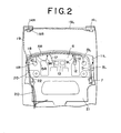
- Fig. 2 is a plane view of the wiring arrangement shown in Fig. 1.
- . there are essentially two cable arrangements represented by single lines including solid and hatched lines connected to a defroster sensor, a radio antenna and a rear-defroster device, and parallel double lines including solid and hatched lines connected to the other electrical devices such as a lamp provided in a rear trunk, tail lamps, audio speakers, a motor for a rear wiper, an air cleaner and so on.
- the hatched lines represent cables attached to the rear surface of a shield panel.
- the reference numeral 1 denotes an antenna for a radio receiver.
- the numeral 2 denotes a rear defroster.
- the antenna 1 and the rear defroster 2 comprise a plurality of wires installed on the inner surface of a rear windshield 3 and connected to power supply terminals 4R and 4L at either end.
- the antenna 1 and the rear defroster 2 are electrically integral so that the rear defroster 2 is also utilized as an antenna, thereby improving sensitivity of the antenna 1 in AM band.
- the antenna 1 is further provided with an output terminal "AT" which is connected to a radio receiver mounted on an instrument panel via a shielded wire (not shown).
- a cable 5R is connected to the terminal 4R and arranged in such manner that the cable 5R leads across the figure along the upper surface of a rear parcel tray panel 6.
- a cable 5L is connected to the terminal 4L on the right side of the figure.
- the cables 5R and 5L are connected to an induction filter 7 for reducing high frequency noise which is provided under the panel 6.
- the cables 5R and 5L are bundled together into a cable 5 after passing through the filter 7.
- the cable 5 runs along the underside of the panel 6 toward the left in the figure.
- the reference numeral 8 denotes a control sensor for the rear defroster 2 which is positioned under the rear defroster 2.
- the sensor 8 detects the condition of the rear defroster 2 and actuates a switching means for the rear defroster 2.
- the sensor 8 is provided at either end with cables 9R and 9L, which pass through the panel 6 and are bunched with the cable 5 under the panel 6.
- the composite cable is denoted by the reference numeral 10.
- the cables 5R, 5L, 5, 9R, 9L, and 10 will be referred to as "defroster cables”.
- the reference numerals llR and 11L denote audio speakers provided at the rear of the vehicle.
- the reference numeral 12 denotes a lamp for a trunk compartment.
- the reference numeral 13 denotes an air cleaner for the passenger compartment.
- the numerals 14R and 14L denote combination tail lamps mounted on either side of the far rear end of vehicle. Cables 15R and 15L connected to the speakers llR and 11L respectively, a cable 16 connected to the trunk lamp 12, and a cable 17 connected to the air cleaner 13 are bunched with the cable 5 and the cable 10 under the tray panel 6, thereby forming a single cable 18.
- hatched portions represent assembled or bundled composite cables.
- a cable 19L connected to the combination tail lamp 14L leads to the other lamp 14n and is bunched with a cable 19R from the lamp 14R.
- the assembled cable 19 leads along the inner surface of the rear right-quarter panel. Under the tray panel 6 the cable 19 joins the cable 18, thereby forming a main cable 20.
- the main cable 20 runs forwards along on the upper surface of a rear-seat back body panel 21.
- the cables 9R and 9L connected to the defroster sensor 8 are further provided with an amplifier 22 for the defroster sensor 8.
- cables 15R, 15L, 16, 17, 19R and 19L connected to each electrical device are referred to generically as "electrical device cables”.
- the cable 10 including the cable 5 connected to the defroster 2 and the cables 9R and 9L connected to the defroster sensor 8 are joined with the electric equipment cables for a long distance as shown by the hatched portion of Figs. 1 and 2.
- switching means of the electrical devices are actuated, switching noises are generated and are transmitted along the electrical device cables.
- the noise signals are induced in the cables connected to the defroster 2 and the sensor 8, and thus the noise signals can easily interfere with the signal from the radio antenna 1. Accordingly, radio noise is increased, which bothers the driver and passengers.
- it is generally required to take countermeasures such as noise preventive devices mounted on each electrical device which might generate noise. Such countermeasures necessitate extra assembling processes and parts thereby increasing cost as previously noted.
- FIGs. 3, 4, and 5 there is shown a wiring arrangement embodied according to the present invention.
- the same reference numerals denote the same or corresponding parts or elements as shown in Figs. 1 and 2 in order to avoid confusion. Therefore, description of similar parts will not be repeated.
- the cables connected to the electrical devices such as the trunk lamp 12, the air cleaner 13, the audio speakers llR and 11L, and the combination lamps 14R and 14L are arranged in the same manner as the conventional arrangement as shown in Figs. 1 and 2.
- the induction filter 7 for reducing high frequency noise is provided, at its input terminal, with a cable 25 which leads towards the left in Fig. 3 along the rear seat back body panel 21.
- the cable 25 is isolated from the electrical device cables such as 15L, 16, 17, and 15R.
- the rear defroster sensor 8 is provided at each terminal with cables 29R and 29L which lead independently forwards in the vehicle along the upper surface of the tray panel 6. They are bunched together at the upper edge of the panel 21 and then connected to the defroster sensor amplifier 22. That is, the cables 29R and 29L are isolated from the electrical device cables.
- a cable 30 leading out of the amplifier 22 is bunched with the cable 25.
- the assembled cable is bundled with a cable 31, which includes the electrical device cables, thereby forming the rear-main cable.20.
- ceramic condensers 32R and 32L having capacitance of about 0.01 V F are provided respectively in the space defined between the panel 21 and the cables 29R. or 29L so as to reduce signal noise.
- the cables connected to the defroster and the defroster sensor such as 5R, 5L, 25, 30, 29R and 29L, hereinafter referred to as "defroster cables", are isolated from the electrical device cables, thereby protecting the defroster cable from noise signals transmitted along the electrical device cables.
- the condenser 32R or 32L is installed on the output side of the amplifier 22, i.e., interposed between the rear seat back body panel 21 and the cable 30, the arrangement results in less noise-reducing effect than that of the previous arrangement.
- the defroster cables located behind the rear seat back body panel 21 and the electrical device cables are isolated from one another by the tray panel 6 so that the tray panel 6 functions as a shield panel. Furthermore, it is always necessary that the confluent point 33 of the cable 31 and the cable 30 be located at least in front of a rear seat back panel 34 which is interposed between a floor panel 35 and the rear parcel tray panel 6 as shown in Fig. 5.
- the cable 30 and the cable 31 are bundled together at the confluent point 33 so as to form the rear main cable 20, it is impossible to perfectly prevent noise signal induction from the cable 31 to the cable 30.
- noise signals however weak, are always induced in the cable 30.
- the cable 30 transmits noise signal originally generated in the defroster cables 5R, 5L, 25, 30, 29R, and 29L. Therefore, in this embodiment as previously noted, noise-preventive filter elements are provided in the defroster cables. That is, the induction filter 7 is interposed between the cables 5R and 5L and the cable 25.
- the condenser filters 32R and 32L are connected between the cables 29R and 29L and the vehicle body, respectively. thereby reducing the noise signals from the defroster cables.
- the cable 25 connected to the input terminal of the induction filter 7 is bundled with the cables 5R and 5L which are connected to the output terminal as shown in conventional arrangement, this will possibly interfere with the filtering effect of the induction filter 7 due to noise induction between the input cable 25 and the output cables 5R and 5L. Therefore, it is necessary to arrange them in such a manner that the cable 25 leads forwards as shown in Fig. 1 so as to be isolated from the cables 5R and 5L.
- This embodied wiring arrangement is intended to protect the radio mounted on the vehicle from noise interference. Actually, it should be considered that additional noise, caused by the other cables such as an instrument cable, are also superimposed on the radio antenna signal. However, as is confirmed by experiment, such noises are so weak as to be ignored. Accordingly, the wiring arrangement and the noise-preventive filters provided in the arrangement previously discussed are sufficient to effectively reduce radio noise.
- the output terminal AT of the antenna 1 is connected to the radio receiver (not shown) through a shielded wire (not shown) so that noise cannot be introduced into the radio receiver via the shielded wire.
- the horizontal line represents operations of electrical devices mounted on the vehicle.
- the vertical line represents magnitude of noise measured at the speaker terminal which is indicated by terminal voltage (Vp-p).
- the dark dots represent the data according to conventional arrangement and the blank dots represent that of the present invention. Each dot indicates an average value of data which result from measurements at several points within three frequency ranges of the AM band.
- the arrow represents the noise reducing effect resulting from the present invention.
- the noise due to the electrical devices is attenuated significantly and to a constant degree by employing the . wiring arrangement according to the present invention.
- the wiring arrangement in accordance with the present invention can easily prevent the radio receiver from intercepting the noise generated by several electrical devices.
- this arrangement can be easily utilized in any automotive vehicles in the rear body of which electrical devices, radio antenna, rear defroster and so on are arranged in substantially the same manner as shown in the accompanying drawings.
- noise preventive measures required in the conventional arrangement for each type of vehicles, each electrical device, and the like will be unnecessary, so that the cost of developing new vehicle models will be decreased.
Landscapes
- Engineering & Computer Science (AREA)
- Mechanical Engineering (AREA)
- Fittings On The Vehicle Exterior For Carrying Loads, And Devices For Holding Or Mounting Articles (AREA)
- Installation Of Indoor Wiring (AREA)
- Shielding Devices Or Components To Electric Or Magnetic Fields (AREA)
Applications Claiming Priority (2)
| Application Number | Priority Date | Filing Date | Title |
|---|---|---|---|
| JP166723/80 | 1980-11-28 | ||
| JP55166723A JPS5791612A (en) | 1980-11-28 | 1980-11-28 | Wire harness wiring system |
Publications (2)
| Publication Number | Publication Date |
|---|---|
| EP0053356A1 true EP0053356A1 (fr) | 1982-06-09 |
| EP0053356B1 EP0053356B1 (fr) | 1985-02-27 |
Family
ID=15836552
Family Applications (1)
| Application Number | Title | Priority Date | Filing Date |
|---|---|---|---|
| EP19810109899 Expired EP0053356B1 (fr) | 1980-11-28 | 1981-11-25 | Disposition de câblage dans la partie arrière d'un véhicule automobile |
Country Status (3)
| Country | Link |
|---|---|
| EP (1) | EP0053356B1 (fr) |
| JP (1) | JPS5791612A (fr) |
| DE (1) | DE3169152D1 (fr) |
Cited By (2)
| Publication number | Priority date | Publication date | Assignee | Title |
|---|---|---|---|---|
| EP0776066A1 (fr) * | 1995-11-21 | 1997-05-28 | The Whitaker Corporation | Structure, procédé et contact pour la liaison d'au moins une barette à souder et utilisation de cette structure |
| FR2812137A1 (fr) * | 2000-07-24 | 2002-01-25 | Marwal Systems | Equipement electrique pour vehicules automobiles |
Citations (2)
| Publication number | Priority date | Publication date | Assignee | Title |
|---|---|---|---|---|
| FR2361004A1 (fr) * | 1976-08-07 | 1978-03-03 | Lucas Industries Ltd | Installation combinee de degivreur de vitre arriere de vehicule et d'antenne de reception de radiophonie |
| GB1540464A (en) * | 1976-06-03 | 1979-02-14 | Toyota Motor Co Ltd | Demisting window for use in motor vehicles |
-
1980
- 1980-11-28 JP JP55166723A patent/JPS5791612A/ja active Granted
-
1981
- 1981-11-25 EP EP19810109899 patent/EP0053356B1/fr not_active Expired
- 1981-11-25 DE DE8181109899T patent/DE3169152D1/de not_active Expired
Patent Citations (2)
| Publication number | Priority date | Publication date | Assignee | Title |
|---|---|---|---|---|
| GB1540464A (en) * | 1976-06-03 | 1979-02-14 | Toyota Motor Co Ltd | Demisting window for use in motor vehicles |
| FR2361004A1 (fr) * | 1976-08-07 | 1978-03-03 | Lucas Industries Ltd | Installation combinee de degivreur de vitre arriere de vehicule et d'antenne de reception de radiophonie |
Cited By (3)
| Publication number | Priority date | Publication date | Assignee | Title |
|---|---|---|---|---|
| EP0776066A1 (fr) * | 1995-11-21 | 1997-05-28 | The Whitaker Corporation | Structure, procédé et contact pour la liaison d'au moins une barette à souder et utilisation de cette structure |
| FR2812137A1 (fr) * | 2000-07-24 | 2002-01-25 | Marwal Systems | Equipement electrique pour vehicules automobiles |
| WO2002008020A1 (fr) * | 2000-07-24 | 2002-01-31 | Marwal Systems | Equipement electrique pour vehicules automobiles |
Also Published As
| Publication number | Publication date |
|---|---|
| EP0053356B1 (fr) | 1985-02-27 |
| DE3169152D1 (en) | 1985-04-04 |
| JPS615328B2 (fr) | 1986-02-18 |
| JPS5791612A (en) | 1982-06-07 |
Similar Documents
| Publication | Publication Date | Title |
|---|---|---|
| US6363156B1 (en) | Integrated communication system for a vehicle | |
| US7171006B2 (en) | Vocal sound input apparatus for automotive vehicle | |
| US5428830A (en) | Concealed antenna system with remote variable gain RF amplifier | |
| WO2000045181A1 (fr) | Capteur d'acceleration et systeme de detection d'acceleration | |
| JPH04347935A (ja) | グランド・アイソレート回路 | |
| EP1265457A2 (fr) | Transduction électroacoustique pour véhicules | |
| JP6292233B2 (ja) | アンテナシステム | |
| EP0053356B1 (fr) | Disposition de câblage dans la partie arrière d'un véhicule automobile | |
| KR100339748B1 (ko) | 차량용유리안테나및그설계방법 | |
| US1960938A (en) | Radioreceiver cable connection | |
| JPH0698387A (ja) | 車室内騒音検出用マイクロフォン | |
| US4137501A (en) | Noise suppression device | |
| JPS6339460B2 (fr) | ||
| KR20190055346A (ko) | 안테나 장치, 안테나 장치의 제어 방법 및 안테나 장치를 포함하는 차량 | |
| JP7766928B2 (ja) | 車載用アンテナ装置 | |
| JPH09104260A (ja) | 車載用電子制御装置 | |
| JPS5820568A (ja) | ワイヤハ−ネスの布線方法 | |
| US20040021609A1 (en) | Vehicle antenna device | |
| JP2006173658A (ja) | 自動車用ガラスアンテナの接地構造 | |
| JPH0611679Y2 (ja) | 車載用音響機器の信号伝送装置 | |
| JPS5920746A (ja) | ワイヤハ−ネスの布線方法 | |
| JP2005348317A (ja) | 自動車用ラジオ信号の伝送システム | |
| JPS58167243A (ja) | ワイヤハ−ネスの布線方式 | |
| JPS6246385B2 (fr) | ||
| KR20190029190A (ko) | 안테나 장치 및 그를 가지는 차량 |
Legal Events
| Date | Code | Title | Description |
|---|---|---|---|
| PUAI | Public reference made under article 153(3) epc to a published international application that has entered the european phase |
Free format text: ORIGINAL CODE: 0009012 |
|
| AK | Designated contracting states |
Designated state(s): DE FR GB |
|
| 17P | Request for examination filed |
Effective date: 19820706 |
|
| GRAA | (expected) grant |
Free format text: ORIGINAL CODE: 0009210 |
|
| AK | Designated contracting states |
Designated state(s): DE FR GB |
|
| REF | Corresponds to: |
Ref document number: 3169152 Country of ref document: DE Date of ref document: 19850404 |
|
| ET | Fr: translation filed | ||
| RAP2 | Party data changed (patent owner data changed or rights of a patent transferred) |
Owner name: NISSAN MOTOR CO., LTD. |
|
| PLBE | No opposition filed within time limit |
Free format text: ORIGINAL CODE: 0009261 |
|
| STAA | Information on the status of an ep patent application or granted ep patent |
Free format text: STATUS: NO OPPOSITION FILED WITHIN TIME LIMIT |
|
| 26N | No opposition filed | ||
| PGFP | Annual fee paid to national office [announced via postgrant information from national office to epo] |
Ref country code: FR Payment date: 19910930 Year of fee payment: 11 |
|
| PG25 | Lapsed in a contracting state [announced via postgrant information from national office to epo] |
Ref country code: FR Effective date: 19930730 |
|
| REG | Reference to a national code |
Ref country code: FR Ref legal event code: ST |
|
| PGFP | Annual fee paid to national office [announced via postgrant information from national office to epo] |
Ref country code: DE Payment date: 20001120 Year of fee payment: 20 |
|
| PGFP | Annual fee paid to national office [announced via postgrant information from national office to epo] |
Ref country code: GB Payment date: 20001122 Year of fee payment: 20 |
|
| PG25 | Lapsed in a contracting state [announced via postgrant information from national office to epo] |
Ref country code: GB Free format text: LAPSE BECAUSE OF EXPIRATION OF PROTECTION Effective date: 20011124 |
|
| REG | Reference to a national code |
Ref country code: GB Ref legal event code: PE20 Effective date: 20011124 |