EP0053420A1 - Verfahren zum Befestigen des Dichtungsgliedes einer Schraubverbindung an einem Ende eines Hochdruckrohres - Google Patents
Verfahren zum Befestigen des Dichtungsgliedes einer Schraubverbindung an einem Ende eines Hochdruckrohres Download PDFInfo
- Publication number
- EP0053420A1 EP0053420A1 EP19810201292 EP81201292A EP0053420A1 EP 0053420 A1 EP0053420 A1 EP 0053420A1 EP 19810201292 EP19810201292 EP 19810201292 EP 81201292 A EP81201292 A EP 81201292A EP 0053420 A1 EP0053420 A1 EP 0053420A1
- Authority
- EP
- European Patent Office
- Prior art keywords
- sealing member
- pipe
- ball
- steel
- pipe end
- Prior art date
- Legal status (The legal status is an assumption and is not a legal conclusion. Google has not performed a legal analysis and makes no representation as to the accuracy of the status listed.)
- Granted
Links
Images
Classifications
-
- B—PERFORMING OPERATIONS; TRANSPORTING
- B23—MACHINE TOOLS; METAL-WORKING NOT OTHERWISE PROVIDED FOR
- B23K—SOLDERING OR UNSOLDERING; WELDING; CLADDING OR PLATING BY SOLDERING OR WELDING; CUTTING BY APPLYING HEAT LOCALLY, e.g. FLAME CUTTING; WORKING BY LASER BEAM
- B23K1/00—Soldering, e.g. brazing, or unsoldering
- B23K1/19—Soldering, e.g. brazing, or unsoldering taking account of the properties of the materials to be soldered
-
- B—PERFORMING OPERATIONS; TRANSPORTING
- B23—MACHINE TOOLS; METAL-WORKING NOT OTHERWISE PROVIDED FOR
- B23K—SOLDERING OR UNSOLDERING; WELDING; CLADDING OR PLATING BY SOLDERING OR WELDING; CUTTING BY APPLYING HEAT LOCALLY, e.g. FLAME CUTTING; WORKING BY LASER BEAM
- B23K1/00—Soldering, e.g. brazing, or unsoldering
- B23K1/14—Soldering, e.g. brazing, or unsoldering specially adapted for soldering seams
- B23K1/18—Soldering, e.g. brazing, or unsoldering specially adapted for soldering seams circumferential seams, e.g. of shells
-
- F—MECHANICAL ENGINEERING; LIGHTING; HEATING; WEAPONS; BLASTING
- F16—ENGINEERING ELEMENTS AND UNITS; GENERAL MEASURES FOR PRODUCING AND MAINTAINING EFFECTIVE FUNCTIONING OF MACHINES OR INSTALLATIONS; THERMAL INSULATION IN GENERAL
- F16L—PIPES; JOINTS OR FITTINGS FOR PIPES; SUPPORTS FOR PIPES, CABLES OR PROTECTIVE TUBING; MEANS FOR THERMAL INSULATION IN GENERAL
- F16L13/00—Non-disconnectable pipe joints, e.g. soldered, adhesive, or caulked joints
- F16L13/08—Soldered joints
-
- F—MECHANICAL ENGINEERING; LIGHTING; HEATING; WEAPONS; BLASTING
- F16—ENGINEERING ELEMENTS AND UNITS; GENERAL MEASURES FOR PRODUCING AND MAINTAINING EFFECTIVE FUNCTIONING OF MACHINES OR INSTALLATIONS; THERMAL INSULATION IN GENERAL
- F16L—PIPES; JOINTS OR FITTINGS FOR PIPES; SUPPORTS FOR PIPES, CABLES OR PROTECTIVE TUBING; MEANS FOR THERMAL INSULATION IN GENERAL
- F16L27/00—Adjustable joints; Joints allowing movement
- F16L27/02—Universal joints, i.e. with mechanical connection allowing angular movement or adjustment of the axes of the parts in any direction
- F16L27/04—Universal joints, i.e. with mechanical connection allowing angular movement or adjustment of the axes of the parts in any direction with partly-spherical engaging surfaces
- F16L27/047—Universal joints, i.e. with mechanical connection allowing angular movement or adjustment of the axes of the parts in any direction with partly-spherical engaging surfaces held in place by a screwed member having an internal spherical surface
Definitions
- the invention relates to a method of attaching the scaling member of a threaded coupling to one end of a high pressure pipe, the end of the pipe being passed through a hole in the sealing member and fixed therein, which coupling additionally comprises a hollow nut slipped loosely over the pipe and abutting the sealing member, its interior engaging the sealing member to be screwed into a matching part.
- sealing member of hardened steel slipped over the pipe end, whereafter the inner edge of the'part of the pipe inside the hole in the sealing member is expanded or rolled to secure the sealing member, generally spherical, on the pipe; or else a screw connection is used.
- a threaded coupling having a sealing member fixed on the pipe by the known method, for handling a liquid under high pressure, for example to assemble a stuffing box around a bearing, leakage will often occur along the sealing member as a result of damage of the connection between sealing member and pipe when the hollow nut is tightened.
- the object of the invention is to provide an improved method of attaching the sealing member of a threaded coupling to one end of a pipe, the said sealing member being so fixed to the pipe end that no leakage can occur when a threaded coupling is applied.
- the sealing member is fabricated in a steel hardenable at a certain temperature and brazing material is applied around the pipe, so that a brazed connection can be formed at that temperature, whereafter the end of the pipe and the sealing member around it are heated to the said certain temperature, so that the brazing material.will flow between the exterior of the pipe end and the hole through the sealing member, whereupon the parts are cooled so that a brazed connection is obtained between pipe and sealing member, and the sealing member is hardened.
- the sealing member is made of M2 steel, and copper is used as brazing material, in which case the heating temperature is 1110 - 1120 0 C.
- the heating of the pipe and with the sealing member slipped over it may be carried out under a protective atmosphere, for example an atmosphere of cracked ammonia, whereby the sealing member acquires a bright surface so that it need not be further polished.
- a protective atmosphere for example an atmosphere of cracked ammonia
- British Patent 888.055 mentions a method of attaching the sealing member of a threaded coupling to the end of a pipe wherein the said sealing member is soldered to one end of the pipe, with the disadvantage that deposits are formed inside the pipe in the process.
- the pipe end is not inserted in the hole in the sealing member.
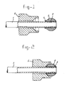
- FIG. 1 shows a pipe end with a sealing member slipped over it prior to heating
- Fig. 2 shows the pipe end with sealing member after heating and cooling.
- a pipe end 1 is inserted in the hole 2 through the sealing member 3, of spherical shape.
- the sealing member 3 consists of a hardenable steel, preferably M2 steel, and the brazing material preferably of copper.
- the assembly shown in Fig. 1 is heated for example to a temperature of 1110 - 1120 C, whereby the brazing material 4 is made to flow into the space between the interior of the hole 2 and the exterior of the pipe end 1, so that after cooling, the brazed connection 5 shown in Fig. 2 is obtained.
- the steel of which the sealing member 3 consists is hardened.
- the heating is preferably carried out in a furnace having a continuous conveyer of wire mesh, in which furnace a protective atmosphere consisting for example of cracked ammonia is present.
- Reference numeral 6 designates the hollow nut forming the threaded coupling together with the sealing member 3.
Landscapes
- Engineering & Computer Science (AREA)
- Mechanical Engineering (AREA)
- General Engineering & Computer Science (AREA)
- Chemical & Material Sciences (AREA)
- Materials Engineering (AREA)
- Non-Disconnectible Joints And Screw-Threaded Joints (AREA)
- Joints With Pressure Members (AREA)
- Heat Treatment Of Articles (AREA)
Applications Claiming Priority (2)
| Application Number | Priority Date | Filing Date | Title |
|---|---|---|---|
| NL8006535A NL8006535A (nl) | 1980-12-01 | 1980-12-01 | Werkwijze voor het aan een eind van een hoge druk pijp bevestigen van het afdichtorgaan van een schroefkoppeling. |
| NL8006535 | 1980-12-01 |
Publications (2)
| Publication Number | Publication Date |
|---|---|
| EP0053420A1 true EP0053420A1 (de) | 1982-06-09 |
| EP0053420B1 EP0053420B1 (de) | 1985-03-06 |
Family
ID=19836266
Family Applications (1)
| Application Number | Title | Priority Date | Filing Date |
|---|---|---|---|
| EP19810201292 Expired EP0053420B1 (de) | 1980-12-01 | 1981-11-23 | Verfahren zum Befestigen des Dichtungsgliedes einer Schraubverbindung an einem Ende eines Hochdruckrohres |
Country Status (4)
| Country | Link |
|---|---|
| EP (1) | EP0053420B1 (de) |
| JP (1) | JPS57118861A (de) |
| DE (1) | DE3169205D1 (de) |
| NL (1) | NL8006535A (de) |
Citations (5)
| Publication number | Priority date | Publication date | Assignee | Title |
|---|---|---|---|---|
| GB888055A (en) * | 1959-07-18 | 1962-01-24 | Johannes Guido | Improvements relating to pipe connections |
| US3198556A (en) * | 1961-05-01 | 1965-08-03 | North American Aviation Inc | Brazed joint and method of making the same |
| US3201154A (en) * | 1960-11-29 | 1965-08-17 | Imp Eastman Corp | Brazed seal connector |
| DE1650121A1 (de) * | 1967-12-14 | 1970-09-24 | Mecano Bundy Gmbh | Rohrfoermige Loetbuchsen zur Verbindung zweier Rohre |
| GB2045376A (en) * | 1979-03-27 | 1980-10-29 | Daimler Benz Ag | Screw-threaded pipe connector device |
Family Cites Families (5)
| Publication number | Priority date | Publication date | Assignee | Title |
|---|---|---|---|---|
| JPS4890909A (de) * | 1972-03-04 | 1973-11-27 | ||
| JPS5532472B2 (de) * | 1972-09-26 | 1980-08-25 | ||
| JPS5382639A (en) * | 1976-12-28 | 1978-07-21 | Daijietsuto Kougiyou Kk | Production of tool with sintered hard alloy tip |
| JPS5811304B2 (ja) * | 1978-10-16 | 1983-03-02 | 本田技研工業株式会社 | 自動二輪車等のフレ−ム |
| JPS55103272A (en) * | 1979-01-30 | 1980-08-07 | Honda Motor Co Ltd | Treating method combining in-furnace brazing and soft-nitriding |
-
1980
- 1980-12-01 NL NL8006535A patent/NL8006535A/nl not_active Application Discontinuation
-
1981
- 1981-11-23 EP EP19810201292 patent/EP0053420B1/de not_active Expired
- 1981-11-23 DE DE8181201292T patent/DE3169205D1/de not_active Expired
- 1981-11-30 JP JP19094381A patent/JPS57118861A/ja active Pending
Patent Citations (5)
| Publication number | Priority date | Publication date | Assignee | Title |
|---|---|---|---|---|
| GB888055A (en) * | 1959-07-18 | 1962-01-24 | Johannes Guido | Improvements relating to pipe connections |
| US3201154A (en) * | 1960-11-29 | 1965-08-17 | Imp Eastman Corp | Brazed seal connector |
| US3198556A (en) * | 1961-05-01 | 1965-08-03 | North American Aviation Inc | Brazed joint and method of making the same |
| DE1650121A1 (de) * | 1967-12-14 | 1970-09-24 | Mecano Bundy Gmbh | Rohrfoermige Loetbuchsen zur Verbindung zweier Rohre |
| GB2045376A (en) * | 1979-03-27 | 1980-10-29 | Daimler Benz Ag | Screw-threaded pipe connector device |
Non-Patent Citations (2)
| Title |
|---|
| Stahlschlussel, 7th Edition 1965, Verlag Stahlschlussel Wegst K.G. Marbach/Neckar (DE) pages 75, 76 and 138 * |
| Werkstatstechnik, Vol. 58, No. 11, 1968, W. MEZGER: "Praktische Erfahrungen mit dem Hartloten unter Schutzgas" pages 538-540 * pages 538 and 539, "Loten im Wanderofen" * * |
Also Published As
| Publication number | Publication date |
|---|---|
| EP0053420B1 (de) | 1985-03-06 |
| JPS57118861A (en) | 1982-07-23 |
| DE3169205D1 (en) | 1985-04-11 |
| NL8006535A (nl) | 1982-07-01 |
Similar Documents
| Publication | Publication Date | Title |
|---|---|---|
| US2308307A (en) | Pipe, pipe lining, and method of making same | |
| US5720504A (en) | Convoluted fluid connector assembly with hardened end portion | |
| US2763923A (en) | Method of and transition member for weld uniting dissimilar metals | |
| US4784311A (en) | Process of producing thick-walled composite metal tubing | |
| RU2000106524A (ru) | Труба нагревательной печи, способ ее использования и способ ее изготовления | |
| US4527818A (en) | Coupling for pipe or tubing | |
| KR19990066872A (ko) | 프로필 클램프와 그 제조방법 | |
| KR930002866B1 (ko) | 고압유체 공급관의 제조방법 | |
| JPH02247085A (ja) | 厚肉細径燃料噴射管及びその製造方法 | |
| US4314861A (en) | Manufacturing method of elbows made of cast stainless steel | |
| JPS58500079A (ja) | 配管、パイプおよび導管用連結装置とそのような装置の製造法 | |
| CN116412312B (zh) | 一种外套式连续油管修复装置及基于其的连续油管修复方法 | |
| US3195936A (en) | Special sleeve and coupling b-nuts | |
| EP0053420B1 (de) | Verfahren zum Befestigen des Dichtungsgliedes einer Schraubverbindung an einem Ende eines Hochdruckrohres | |
| GB2134614A (en) | Pipe connection | |
| DE10118198A1 (de) | Rohrverbindungsanordnung | |
| JPS58211066A (ja) | ガスケツトの改良 | |
| EP0647302A1 (de) | Druckgelenk | |
| DE19922466A1 (de) | Verfahren zur Herstellung eines elektromagnetischen Ventils | |
| JPH0576383B2 (de) | ||
| GB2154492A (en) | Mechanical stress improvement process | |
| JPH1082501A (ja) | 高速増殖炉用2重管およびその製造方法 | |
| SU1488128A1 (ru) | Составна матрица дл прессовани порошков | |
| JPH0412286Y2 (de) | ||
| GB2278169A (en) | Cast pipe fittings |
Legal Events
| Date | Code | Title | Description |
|---|---|---|---|
| PUAI | Public reference made under article 153(3) epc to a published international application that has entered the european phase |
Free format text: ORIGINAL CODE: 0009012 |
|
| AK | Designated contracting states |
Designated state(s): CH DE FR GB IT NL SE |
|
| 17P | Request for examination filed |
Effective date: 19821206 |
|
| ITF | It: translation for a ep patent filed | ||
| GRAA | (expected) grant |
Free format text: ORIGINAL CODE: 0009210 |
|
| AK | Designated contracting states |
Designated state(s): CH DE FR GB IT LI NL SE |
|
| REF | Corresponds to: |
Ref document number: 3169205 Country of ref document: DE Date of ref document: 19850411 |
|
| ET | Fr: translation filed | ||
| PLBE | No opposition filed within time limit |
Free format text: ORIGINAL CODE: 0009261 |
|
| STAA | Information on the status of an ep patent application or granted ep patent |
Free format text: STATUS: NO OPPOSITION FILED WITHIN TIME LIMIT |
|
| 26N | No opposition filed | ||
| PGFP | Annual fee paid to national office [announced via postgrant information from national office to epo] |
Ref country code: SE Payment date: 19910930 Year of fee payment: 11 Ref country code: CH Payment date: 19910930 Year of fee payment: 11 |
|
| PGFP | Annual fee paid to national office [announced via postgrant information from national office to epo] |
Ref country code: FR Payment date: 19911008 Year of fee payment: 11 |
|
| PGFP | Annual fee paid to national office [announced via postgrant information from national office to epo] |
Ref country code: GB Payment date: 19911011 Year of fee payment: 11 |
|
| PGFP | Annual fee paid to national office [announced via postgrant information from national office to epo] |
Ref country code: DE Payment date: 19911102 Year of fee payment: 11 |
|
| ITTA | It: last paid annual fee | ||
| PGFP | Annual fee paid to national office [announced via postgrant information from national office to epo] |
Ref country code: NL Payment date: 19911130 Year of fee payment: 11 |
|
| PG25 | Lapsed in a contracting state [announced via postgrant information from national office to epo] |
Ref country code: GB Effective date: 19921123 |
|
| PG25 | Lapsed in a contracting state [announced via postgrant information from national office to epo] |
Ref country code: SE Effective date: 19921124 |
|
| PG25 | Lapsed in a contracting state [announced via postgrant information from national office to epo] |
Ref country code: LI Effective date: 19921130 Ref country code: CH Effective date: 19921130 |
|
| PG25 | Lapsed in a contracting state [announced via postgrant information from national office to epo] |
Ref country code: NL Effective date: 19930601 |
|
| NLV4 | Nl: lapsed or anulled due to non-payment of the annual fee | ||
| GBPC | Gb: european patent ceased through non-payment of renewal fee |
Effective date: 19921123 |
|
| PG25 | Lapsed in a contracting state [announced via postgrant information from national office to epo] |
Ref country code: FR Effective date: 19930730 |
|
| REG | Reference to a national code |
Ref country code: CH Ref legal event code: PL |
|
| PG25 | Lapsed in a contracting state [announced via postgrant information from national office to epo] |
Ref country code: DE Effective date: 19930803 |
|
| REG | Reference to a national code |
Ref country code: FR Ref legal event code: ST |
|
| EUG | Se: european patent has lapsed |
Ref document number: 81201292.0 Effective date: 19930610 |