EP0053636B1 - Procédé et dispositif d'étirage en une ou plusieurs étapes - Google Patents
Procédé et dispositif d'étirage en une ou plusieurs étapes Download PDFInfo
- Publication number
- EP0053636B1 EP0053636B1 EP19800108196 EP80108196A EP0053636B1 EP 0053636 B1 EP0053636 B1 EP 0053636B1 EP 19800108196 EP19800108196 EP 19800108196 EP 80108196 A EP80108196 A EP 80108196A EP 0053636 B1 EP0053636 B1 EP 0053636B1
- Authority
- EP
- European Patent Office
- Prior art keywords
- lubricant
- chambers
- stage
- die
- liquid
- Prior art date
- Legal status (The legal status is an assumption and is not a legal conclusion. Google has not performed a legal analysis and makes no representation as to the accuracy of the status listed.)
- Expired
Links
Images
Classifications
-
- B—PERFORMING OPERATIONS; TRANSPORTING
- B21—MECHANICAL METAL-WORKING WITHOUT ESSENTIALLY REMOVING MATERIAL; PUNCHING METAL
- B21C—MANUFACTURE OF METAL SHEETS, WIRE, RODS, TUBES, PROFILES OR LIKE SEMI-MANUFACTURED PRODUCTS OTHERWISE THAN BY ROLLING; AUXILIARY OPERATIONS USED IN CONNECTION WITH METAL-WORKING WITHOUT ESSENTIALLY REMOVING MATERIAL
- B21C9/00—Cooling, heating or lubricating drawing material
-
- B—PERFORMING OPERATIONS; TRANSPORTING
- B21—MECHANICAL METAL-WORKING WITHOUT ESSENTIALLY REMOVING MATERIAL; PUNCHING METAL
- B21C—MANUFACTURE OF METAL SHEETS, WIRE, RODS, TUBES, PROFILES OR LIKE SEMI-MANUFACTURED PRODUCTS OTHERWISE THAN BY ROLLING; AUXILIARY OPERATIONS USED IN CONNECTION WITH METAL-WORKING WITHOUT ESSENTIALLY REMOVING MATERIAL
- B21C1/00—Manufacture of metal sheets, wire, rods, tubes or like semi-manufactured products by drawing
- B21C1/02—Drawing metal wire or like flexible metallic material by drawing machines or apparatus in which the drawing action is effected by drums
- B21C1/04—Drawing metal wire or like flexible metallic material by drawing machines or apparatus in which the drawing action is effected by drums with two or more dies operating in series
-
- B—PERFORMING OPERATIONS; TRANSPORTING
- B21—MECHANICAL METAL-WORKING WITHOUT ESSENTIALLY REMOVING MATERIAL; PUNCHING METAL
- B21C—MANUFACTURE OF METAL SHEETS, WIRE, RODS, TUBES, PROFILES OR LIKE SEMI-MANUFACTURED PRODUCTS OTHERWISE THAN BY ROLLING; AUXILIARY OPERATIONS USED IN CONNECTION WITH METAL-WORKING WITHOUT ESSENTIALLY REMOVING MATERIAL
- B21C3/00—Profiling tools for metal drawing; Combinations of dies and mandrels for metal drawing
- B21C3/02—Dies; Selection of material therefor; Cleaning thereof
- B21C3/12—Die holders; Rotating dies
- B21C3/14—Die holders combined with devices for guiding the drawing material or combined with devices for cooling, heating, or lubricating
Definitions
- the invention relates to the field of metallurgy. According to the preamble of claim 1, it relates to a method for single-stage or multi-stage drawing and lubrication of metal material to be formed in the form of wires, rods, tubes, profiles and the like. Bare metal or lubricated metal can be used as the starting material.
- a liquid lubricant is applied to the material to be formed before the forming.
- the lubricants it is already known from DE-C-969 263 to coat the material to be formed in a pass through an open box which contains the lubricant.
- a scraper in the inlet and outlet for the material to be formed, usually consisting of a felt or plastic material plate with a slot through which the material to be formed is passed. These wipers are intended to seal the box and ensure the formation of a uniform film of lubricant.
- a deficiency of this device is that the solvent contained in the lubricant can evaporate, as a result of which solvent depletion occurs and, in the case of special solvents, special measures for health protection have to be carried out.
- Another disadvantage is that this device is only functional in a horizontal arrangement. In addition, a constant, even application of lubricant is not guaranteed because the wipers wear out quickly. In the event of wear, larger amounts of lubricant are also carried out of the box. If there are contaminants on the surface of the drawing material, e.g. B. grease residues, no closed lubricant film can be achieved with this device.
- liquid lubricants that consist of solutions or dispersions of solid or semi-solid lubricants
- the applied liquid lubricant layer must be dried before the forming tool so that the advantages of the solid or semi-solid lubricant can be fully exploited.
- the liquid contained in the lubricant must be removed before the material to be formed is introduced into the forming tool. Removal must be carried out very carefully, as the dynamic viscosity of the lubricant decreases if it is not adequately dried.
- To remove the liquid it is already known to dry the coated material in drying ovens. This process is very time consuming, particularly for lubricants containing a high boiling point liquid.
- Various forms of pressure-drawing tools are used for drawing with hydrodynamic lubrication.
- One of these known pressure-drawing tools contains a run-in die and a working die, arranged one after the other in a two-part housing, a pressure space being formed between them.
- solid lubricant is conveyed into the pressure chamber in front of the working die through the inlet die together with the incoming material.
- the lubricant is liquefied under the influence of the pressure that builds up and the frictional heat and pressed into the drawing hole between the drawing material and the working die.
- a deficiency of this procedure is that there is a completely inadequate residual lubricant coating for the subsequent drawing operations on the drawing material which emerges from the working die.
- the aim of the invention is to create conditions for a simplification of the technological process stages and facilities, an increase in the possible forming speed and the possible degree of forming, a reduction in the wear of drawing tools and improvement of the surface quality, as well as for an increase in work productivity and for tapping performance reserves when single or multi-stage drag.
- the invention has for its object to develop a adaptable to a wide variety of forming conditions, simple technology for single or multi-stage drawing, in which special methods and devices for applying and drying a liquid lubricant in front of the drawing tools avoided, each drawing tool with a sufficient amount Lubricant supplied and if necessary a re-coating of the formed material is possible or an appreciable lubricant residue can be avoided.
- This object is achieved according to the invention in a generic method in that the material to be formed is drawn in a straight line and in one go and during operation before each forming stage with a liquid lubricant containing a solid lubricant, consisting of an organic solvent, such as trichlorethylene or benzene as a liquid lubricant and fatty acid salts dissolved therein, such as calcium stearate, as a solid lubricant, passes through several closed chambers and the lubricant corresponds to the respective forming conditions Has lubricant concentration.
- a liquid lubricant containing a solid lubricant consisting of an organic solvent, such as trichlorethylene or benzene as a liquid lubricant and fatty acid salts dissolved therein, such as calcium stearate, as a solid lubricant
- the lubricant concentration in the lubricant is expediently varied depending on the respective forming conditions.
- the flooding or emptying of the chambers and the variation of the lubricant concentration are expediently carried out during the forming process in accordance with a program which is matched to the respective forming conditions.
- the material to be formed is expediently drawn through a chamber which is equipped with two or more working dies, one working die of which is located in the inlet and one in the outlet opening of the chamber and the material to be heated as a result of the deformation between the working dies by flooding the Chamber is contacted with the lubricant during the forming.
- the material to be formed can also be drawn through a chamber which is equipped with only one working die located in the inlet opening, the material to be heated as a result of the forming being immediately after its exit from the working die by flooding the chamber with the liquid Lubricant is contacted for the purpose of a re-coating and is subsequently fed to drying.
- the invention also relates to a device for carrying out the method, with the feature that the device consists of a plurality of closed chambers arranged one behind the other for a rectilinear passage of the material to be formed, the chambers being assigned supply lines and a respective discharge line and a drawing die in each of the chambers is arranged centrally.
- the good properties of lubricants which contain a solid or semi-solid lubricant in a liquid can be largely exploited.
- Another important advantage of the invention is that it is a high-performance solution that is easily adaptable to most of the different forming conditions that occur in practice and is therefore universally applicable.
- materials can be formed which differ significantly from one another in terms of their strength, with design changes to the device not being necessary.
- the forming technology can be optimally matched to the respective forming conditions, so that power reserves when drawing metal forming material are tapped and large degrees of forming, high drawing speeds and a product quality corresponding to the respective requirements can be achieved in the complex.
- the invention is based on a new operating principle. This consists of the fact that a thin, dry film of the solid or semi-solid lubricant contained in the lubricant is formed on the material to be formed in the chambers contacted with liquid lubricant immediately before the drawing die of the working dies without special drying devices, since as a result of the forming heat generated in the material to be formed - this also counteracts the transport direction is directed in front of the working die - the liquid contained in the lubricant evaporates quickly in front of the working die and a gas bubble forms around the material to be formed, which separates the lubricant film from the liquid lubricant in the chamber. This ensures that, even at very high drawing speeds, a forming material provided with a dry lubricant film runs into the working die and thus the advantages adhering to the solid lubricants, in particular their high dynamic viscosity, come into their own.
- the new operating principle ensures that only a very thin, but completely sufficient lubricant film is created. This advantageously means that no more lubricant is supplied to the drawing hole than is necessary to maintain good lubrication conditions.
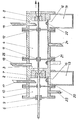
- the drawing shows a schematic sectional view of a device which consists of lined up chambers 1 to 5.
- a material to be formed 6 is drawn through these chambers from left to right.
- a collecting space 13; 14 for stripped dry lubricant which by means of flaps 15; 16 opposite the chambers 2; 5 can be sealed liquid-tight.
- the Chambers 2; 3; 5 can lead 17; 18; 19 in connection with leads 20; 21; 22 operated with a liquid lubricant either flooded or emptied, expediently according to a certain program.
- Calcium stearate dissolved in trichlorethylene is used as the liquid lubricant in this embodiment.
- the lubricant is located in a lubricant reservoir, not shown in the drawing, which is connected to the supply lines 17; 18; 19 and the leads 20; 21; 22 is connected to a lubricant circuit.
- the flooding of the chambers 2; 3; 5 is carried out by means of a lubricant pump arranged in the lubricant reservoir. That from the chambers 2; 3; 5 Lubricant flowing back into the lubricant reservoir is thermostatted and cleaned there.
- Liquid lubricant which possibly penetrates from the chamber 2 via the sealing element 10 into the chamber 1, or from the chambers 3; 5 via the sealing elements 11; 12 into the chamber 4, is by means of lines 23; 24 returned to the lubricant reservoir.
- the chamber 4 is with the chambers 3; 5 connected via heat insulating seals 25.
- the device can be switched to another mode of operation during the drawing process, for example by emptying the chamber 3 after the flap 16 has been closed beforehand and the chamber 5 has been flooded with the liquid lubricant.
- this mode of operation the material to be formed leaves the device bare, with an excellent surface quality and without any significant lubricant residue.
- the device described in this exemplary embodiment adapted to the given starting materials, forming conditions and desired product qualities, can be switched to other different operating modes before the start or during the drawing process, some examples of which are listed in the table below.
- the partitions of these chambers to the chamber 4 and the line 24 can be dispensed with, so that the device can be constructed correspondingly simpler and shorter.
- a further simplification is possible if the chamber 2 is not to be flooded.
- all of the structural parts arranged in front of the working die 7 can be omitted, including the collecting space 13.
- chamber 5 can be omitted; in the case of a vertical arrangement with the wire drawing direction running upwards, the partition between the chambers 3 and 4 is also formed.
- the wire is formed in one step and coated.
Landscapes
- Engineering & Computer Science (AREA)
- Mechanical Engineering (AREA)
- Metal Extraction Processes (AREA)
Claims (5)
Applications Claiming Priority (2)
| Application Number | Priority Date | Filing Date | Title |
|---|---|---|---|
| DD225895 | 1980-12-09 | ||
| DD22589580A DD154334A1 (de) | 1980-12-09 | 1980-12-09 | Verfahren zum schmieren des ziehhols bei drahtziehmaschinen |
Publications (2)
| Publication Number | Publication Date |
|---|---|
| EP0053636A1 EP0053636A1 (fr) | 1982-06-16 |
| EP0053636B1 true EP0053636B1 (fr) | 1985-06-19 |
Family
ID=5527763
Family Applications (1)
| Application Number | Title | Priority Date | Filing Date |
|---|---|---|---|
| EP19800108196 Expired EP0053636B1 (fr) | 1980-12-09 | 1980-12-24 | Procédé et dispositif d'étirage en une ou plusieurs étapes |
Country Status (3)
| Country | Link |
|---|---|
| EP (1) | EP0053636B1 (fr) |
| DD (1) | DD154334A1 (fr) |
| DE (1) | DE3070795D1 (fr) |
Families Citing this family (8)
| Publication number | Priority date | Publication date | Assignee | Title |
|---|---|---|---|---|
| DD210524A3 (de) * | 1981-07-09 | 1984-06-13 | Adw Ddr | Verfahren zum mehrstufigen ziehen |
| LU84257A1 (fr) * | 1982-07-05 | 1984-03-22 | Lamitref Aluminium | Procede de fabrication de fil metallique,fil metallique ainsi obtenu et unite de production utilisee pour appliquer ce procede |
| US4553416A (en) * | 1983-06-20 | 1985-11-19 | Sumitomo Metal Industries, Ltd. | Dry type continuous wire drawing process |
| GB8328843D0 (en) * | 1983-10-28 | 1983-11-30 | Marshall Richards Barcro Ltd | Wire drawing |
| DE3571562D1 (en) * | 1984-05-21 | 1989-08-24 | Sumitomo Metal Ind | Method for continuous drawing of wire rod |
| DE19817088C2 (de) * | 1998-04-17 | 2000-02-17 | Ecoform Umformtechnik Gmbh | Verfahren und Vorrichtung zum Beschichten und Umformen von strangförmigem metallischem Umformgut mittels Ziehen |
| CN115415345B (zh) * | 2022-09-23 | 2025-11-04 | 江苏阳铭互联智能系统有限公司 | 拉丝机的油脂收集结构 |
| CN115875455A (zh) * | 2022-12-22 | 2023-03-31 | 陕西光德电子材料有限公司 | 拉制光伏用铜杆防漏液装置及太阳能用轴装焊带 |
Family Cites Families (7)
| Publication number | Priority date | Publication date | Assignee | Title |
|---|---|---|---|---|
| US1659591A (en) * | 1925-04-08 | 1928-02-21 | American Steel & Wire Co | Wire-drawing bench |
| DE513459C (de) * | 1929-09-14 | 1930-11-28 | Walther Nacken | Anordnung der Ziehsteine bei Mehrfach-Drahtziehmaschinen |
| US2203751A (en) * | 1938-02-26 | 1940-06-11 | Simons Abraham | Method of and apparatus for drawing wire |
| DE969263C (de) * | 1954-05-07 | 1958-05-14 | Felten & Guilleaume Carlswerk | Verfahren und Vorrichtung zum Blankziehen von Stahldraehten oder -staeben mit starker Querschnittsabnahme |
| US3413832A (en) * | 1965-07-27 | 1968-12-03 | Nat Standard Co | Wire drawing method |
| US3686908A (en) * | 1971-02-01 | 1972-08-29 | Wire Technology And Machinery | Wire drawing apparatus and method |
| AT353737B (de) * | 1976-09-16 | 1979-11-26 | Langenecker Bertwin Dr | Verfahren und vorrichtung zum ziehen von draehten, stangen, rohren u.dgl. |
-
1980
- 1980-12-09 DD DD22589580A patent/DD154334A1/de unknown
- 1980-12-24 EP EP19800108196 patent/EP0053636B1/fr not_active Expired
- 1980-12-24 DE DE8080108196T patent/DE3070795D1/de not_active Expired
Also Published As
| Publication number | Publication date |
|---|---|
| DD154334A1 (de) | 1982-03-17 |
| EP0053636A1 (fr) | 1982-06-16 |
| DE3070795D1 (en) | 1985-07-25 |
Similar Documents
| Publication | Publication Date | Title |
|---|---|---|
| EP0053636B1 (fr) | Procédé et dispositif d'étirage en une ou plusieurs étapes | |
| EP0013012B1 (fr) | Dispositif pour l'application d'un lubrifiant à une matière à déformer | |
| DE2325343C3 (de) | ölzuführungsvorrichtung für eine Stevenrohrlagerung | |
| EP0112437A1 (fr) | Outil pour un traitement précis et finissage de coupes cylindriques | |
| WO2020221654A1 (fr) | Laminage d'un produit laminé | |
| DE3619219A1 (de) | Verfahren und vorrichtung zur kondensation von zinkdampf | |
| EP3122481A1 (fr) | Dispositif pour appliquer et aspirer des consommables à l'entrée de laminoirs à froid | |
| WO2019243468A1 (fr) | Système de circulation d'émulsion | |
| DE19721650C2 (de) | Vorrichtung zur Aerosolerzeugung | |
| DE2314415C3 (de) | Schmiermittel für das Halbwarmschmieden, insbesondere von Stahl in Drahtform | |
| EP0013013A1 (fr) | Procédé et dispositif pour déposer et sécher des lubrifiants liquides | |
| DD148007A1 (de) | Verfahren und vorrichtung zum ein-oder mehrstufigen ziehen | |
| DE69619201T2 (de) | Verfahren zur schmierung von mechnanischen teilen und einrichtungen zur durchführung des verfahrens | |
| DD148010A1 (de) | Verfahren und vorrichtung zum ziehen von metallischem umformgut | |
| DE2519905A1 (de) | Verfahren zur herstellung von tiefgezogenen und/oder abstreckgezogenen dosen aus weissblech | |
| DD148003A1 (de) | Verfahren und vorrichtung zum ziehen metallischen umformgutes | |
| DE19909245B4 (de) | Einrichtung zum Aufbringen von viskosem Material auf eine zu beschichtende Fläche | |
| DD148012A1 (de) | Verfahren zum nassziehen von draht | |
| DD210526A3 (de) | Verfahren zum ein- oder mehrstufigen ziehen von metallischem umformgut | |
| DD148004A1 (de) | Verfahren und vorrichtung zum einstufigen ziehen metallischen umformgutes | |
| DD148005A1 (de) | Verfahren und vorrichtung zum einstufigen ziehen | |
| DD148006A1 (de) | Verfahren und vorrichtung zum mehrstufigen ziehen metallischen umformgutes | |
| DD148009B1 (de) | Verfahren zum mehrstufigen trockenziehen | |
| EP0060373A2 (fr) | Dispositif pour lubrifier des tôles en forme de rubans ou de plaques | |
| DD147207A1 (de) | Verfahren und vorrichtung zum aufbringen fluessiger schmiermittel |
Legal Events
| Date | Code | Title | Description |
|---|---|---|---|
| PUAI | Public reference made under article 153(3) epc to a published international application that has entered the european phase |
Free format text: ORIGINAL CODE: 0009012 |
|
| AK | Designated contracting states |
Designated state(s): DE FR GB IT NL SE |
|
| 17P | Request for examination filed |
Effective date: 19820729 |
|
| RAP1 | Party data changed (applicant data changed or rights of an application transferred) |
Owner name: VEB SCHWERMASCHINENBAU-KOMBINAT ERNST THAELMANN M |
|
| ITF | It: translation for a ep patent filed | ||
| GRAA | (expected) grant |
Free format text: ORIGINAL CODE: 0009210 |
|
| AK | Designated contracting states |
Designated state(s): DE FR GB IT NL SE |
|
| REF | Corresponds to: |
Ref document number: 3070795 Country of ref document: DE Date of ref document: 19850725 |
|
| ET | Fr: translation filed | ||
| PLBE | No opposition filed within time limit |
Free format text: ORIGINAL CODE: 0009261 |
|
| STAA | Information on the status of an ep patent application or granted ep patent |
Free format text: STATUS: NO OPPOSITION FILED WITHIN TIME LIMIT |
|
| 26N | No opposition filed | ||
| GBPC | Gb: european patent ceased through non-payment of renewal fee | ||
| REG | Reference to a national code |
Ref country code: GB Ref legal event code: 728C |
|
| PGFP | Annual fee paid to national office [announced via postgrant information from national office to epo] |
Ref country code: NL Payment date: 19861231 Year of fee payment: 7 |
|
| REG | Reference to a national code |
Ref country code: GB Ref legal event code: 728A |
|
| PG25 | Lapsed in a contracting state [announced via postgrant information from national office to epo] |
Ref country code: SE Effective date: 19871225 |
|
| PG25 | Lapsed in a contracting state [announced via postgrant information from national office to epo] |
Ref country code: NL Effective date: 19880701 |
|
| NLV4 | Nl: lapsed or anulled due to non-payment of the annual fee | ||
| GBPC | Gb: european patent ceased through non-payment of renewal fee | ||
| PG25 | Lapsed in a contracting state [announced via postgrant information from national office to epo] |
Ref country code: FR Free format text: LAPSE BECAUSE OF NON-PAYMENT OF DUE FEES Effective date: 19880831 |
|
| PG25 | Lapsed in a contracting state [announced via postgrant information from national office to epo] |
Ref country code: DE Effective date: 19880901 |
|
| REG | Reference to a national code |
Ref country code: FR Ref legal event code: ST |
|
| PG25 | Lapsed in a contracting state [announced via postgrant information from national office to epo] |
Ref country code: GB Effective date: 19881118 |
|
| EUG | Se: european patent has lapsed |
Ref document number: 80108196.9 Effective date: 19880912 |