EP0054199A1 - Elément de construction préfabriqué - Google Patents
Elément de construction préfabriqué Download PDFInfo
- Publication number
- EP0054199A1 EP0054199A1 EP81109829A EP81109829A EP0054199A1 EP 0054199 A1 EP0054199 A1 EP 0054199A1 EP 81109829 A EP81109829 A EP 81109829A EP 81109829 A EP81109829 A EP 81109829A EP 0054199 A1 EP0054199 A1 EP 0054199A1
- Authority
- EP
- European Patent Office
- Prior art keywords
- building element
- element according
- insulating material
- ribs
- frame
- Prior art date
- Legal status (The legal status is an assumption and is not a legal conclusion. Google has not performed a legal analysis and makes no representation as to the accuracy of the status listed.)
- Granted
Links
- 239000011810 insulating material Substances 0.000 claims abstract description 15
- 229910052751 metal Inorganic materials 0.000 claims abstract description 15
- 239000002184 metal Substances 0.000 claims abstract description 15
- 230000002787 reinforcement Effects 0.000 claims abstract description 8
- 238000010276 construction Methods 0.000 claims description 32
- 239000000463 material Substances 0.000 claims description 13
- 239000006260 foam Substances 0.000 claims description 4
- 230000001413 cellular effect Effects 0.000 claims description 2
- 239000000835 fiber Substances 0.000 claims description 2
- 238000005253 cladding Methods 0.000 abstract description 13
- 239000011248 coating agent Substances 0.000 description 11
- 238000000576 coating method Methods 0.000 description 11
- 238000004519 manufacturing process Methods 0.000 description 7
- 238000009413 insulation Methods 0.000 description 6
- 238000009415 formwork Methods 0.000 description 4
- 229920003023 plastic Polymers 0.000 description 4
- 239000004033 plastic Substances 0.000 description 4
- 125000006850 spacer group Chemical group 0.000 description 4
- 229910052782 aluminium Inorganic materials 0.000 description 3
- XAGFODPZIPBFFR-UHFFFAOYSA-N aluminium Chemical compound [Al] XAGFODPZIPBFFR-UHFFFAOYSA-N 0.000 description 3
- 238000009422 external insulation Methods 0.000 description 3
- 238000009434 installation Methods 0.000 description 3
- 230000004888 barrier function Effects 0.000 description 2
- 239000004568 cement Substances 0.000 description 2
- 239000011253 protective coating Substances 0.000 description 2
- 238000007789 sealing Methods 0.000 description 2
- 229920002994 synthetic fiber Polymers 0.000 description 2
- 238000003466 welding Methods 0.000 description 2
- 229910000831 Steel Inorganic materials 0.000 description 1
- 230000000703 anti-shock Effects 0.000 description 1
- 239000011324 bead Substances 0.000 description 1
- 239000011449 brick Substances 0.000 description 1
- 230000006835 compression Effects 0.000 description 1
- 238000007906 compression Methods 0.000 description 1
- 238000009826 distribution Methods 0.000 description 1
- 239000011888 foil Substances 0.000 description 1
- 239000011521 glass Substances 0.000 description 1
- 239000011491 glass wool Substances 0.000 description 1
- 239000002655 kraft paper Substances 0.000 description 1
- 229910001092 metal group alloy Inorganic materials 0.000 description 1
- 230000007935 neutral effect Effects 0.000 description 1
- 229920000573 polyethylene Polymers 0.000 description 1
- 229920002635 polyurethane Polymers 0.000 description 1
- 239000004814 polyurethane Substances 0.000 description 1
- 229920000915 polyvinyl chloride Polymers 0.000 description 1
- 239000004800 polyvinyl chloride Substances 0.000 description 1
- 238000010079 rubber tapping Methods 0.000 description 1
- 239000010454 slate Substances 0.000 description 1
- 239000010959 steel Substances 0.000 description 1
- 238000004078 waterproofing Methods 0.000 description 1
- 239000002023 wood Substances 0.000 description 1
Images

Classifications
-
- E—FIXED CONSTRUCTIONS
- E04—BUILDING
- E04C—STRUCTURAL ELEMENTS; BUILDING MATERIALS
- E04C2/00—Building elements of relatively thin form for the construction of parts of buildings, e.g. sheet materials, slabs, or panels
- E04C2/02—Building elements of relatively thin form for the construction of parts of buildings, e.g. sheet materials, slabs, or panels characterised by specified materials
- E04C2/10—Building elements of relatively thin form for the construction of parts of buildings, e.g. sheet materials, slabs, or panels characterised by specified materials of wood, fibres, chips, vegetable stems, or the like; of plastics; of foamed products
- E04C2/20—Building elements of relatively thin form for the construction of parts of buildings, e.g. sheet materials, slabs, or panels characterised by specified materials of wood, fibres, chips, vegetable stems, or the like; of plastics; of foamed products of plastics
- E04C2/205—Building elements of relatively thin form for the construction of parts of buildings, e.g. sheet materials, slabs, or panels characterised by specified materials of wood, fibres, chips, vegetable stems, or the like; of plastics; of foamed products of plastics of foamed plastics, or of plastics and foamed plastics, optionally reinforced
-
- E—FIXED CONSTRUCTIONS
- E04—BUILDING
- E04B—GENERAL BUILDING CONSTRUCTIONS; WALLS, e.g. PARTITIONS; ROOFS; FLOORS; CEILINGS; INSULATION OR OTHER PROTECTION OF BUILDINGS
- E04B5/00—Floors; Floor construction with regard to insulation; Connections specially adapted therefor
- E04B5/16—Load-carrying floor structures wholly or partly cast or similarly formed in situ
- E04B5/32—Floor structures wholly cast in situ with or without form units or reinforcements
- E04B5/36—Floor structures wholly cast in situ with or without form units or reinforcements with form units as part of the floor
- E04B5/38—Floor structures wholly cast in situ with or without form units or reinforcements with form units as part of the floor with slab-shaped form units acting simultaneously as reinforcement; Form slabs with reinforcements extending laterally outside the element
- E04B5/40—Floor structures wholly cast in situ with or without form units or reinforcements with form units as part of the floor with slab-shaped form units acting simultaneously as reinforcement; Form slabs with reinforcements extending laterally outside the element with metal form-slabs
-
- E—FIXED CONSTRUCTIONS
- E04—BUILDING
- E04C—STRUCTURAL ELEMENTS; BUILDING MATERIALS
- E04C2/00—Building elements of relatively thin form for the construction of parts of buildings, e.g. sheet materials, slabs, or panels
- E04C2/02—Building elements of relatively thin form for the construction of parts of buildings, e.g. sheet materials, slabs, or panels characterised by specified materials
- E04C2/10—Building elements of relatively thin form for the construction of parts of buildings, e.g. sheet materials, slabs, or panels characterised by specified materials of wood, fibres, chips, vegetable stems, or the like; of plastics; of foamed products
- E04C2/16—Building elements of relatively thin form for the construction of parts of buildings, e.g. sheet materials, slabs, or panels characterised by specified materials of wood, fibres, chips, vegetable stems, or the like; of plastics; of foamed products of fibres, chips, vegetable stems, or the like
- E04C2/18—Building elements of relatively thin form for the construction of parts of buildings, e.g. sheet materials, slabs, or panels characterised by specified materials of wood, fibres, chips, vegetable stems, or the like; of plastics; of foamed products of fibres, chips, vegetable stems, or the like with binding wires, reinforcing bars, or the like
-
- Y—GENERAL TAGGING OF NEW TECHNOLOGICAL DEVELOPMENTS; GENERAL TAGGING OF CROSS-SECTIONAL TECHNOLOGIES SPANNING OVER SEVERAL SECTIONS OF THE IPC; TECHNICAL SUBJECTS COVERED BY FORMER USPC CROSS-REFERENCE ART COLLECTIONS [XRACs] AND DIGESTS
- Y10—TECHNICAL SUBJECTS COVERED BY FORMER USPC
- Y10T—TECHNICAL SUBJECTS COVERED BY FORMER US CLASSIFICATION
- Y10T428/00—Stock material or miscellaneous articles
- Y10T428/249921—Web or sheet containing structurally defined element or component
- Y10T428/249953—Composite having voids in a component [e.g., porous, cellular, etc.]
- Y10T428/249987—With nonvoid component of specified composition
- Y10T428/24999—Inorganic
Definitions
- the present invention relates to a versatile construction element, which can be used for the realization of any construction work such as wall, insulating panel for industrial cladding, exterior insulation panel on existing works, roof support, load-bearing floor, collaborating metal floor, etc.
- Multipurpose insulating panels for construction are already known, which generally consist of two facings between which an insulating material is incorporated.
- these panels have drawbacks, among which one can note on the one hand the fact that their versatile character is very limited because of the necessary presence of the two external facings, which can further constitute a double disadvantage from an aesthetic point of view. and from an economic point of view, and further by the fact that thermal bridges can be created during the installation of these panels, which significantly reduces their insulation characteristics.
- the object of this invention to overcome the aforementioned drawbacks therefore consists of a building element, characterized in that it comprises a rigid frame, which is at least partially embedded in an insulating material, so that each of the faces of the building element is at least partly formed by this insulating material.
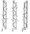
- Figures 1 to 3 are cross-sectional views of three embodiments of the building element.
- FIG. 4 is a perspective view of the construction elements in their use as panels for cladding
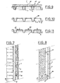
- FIGS. 5 and 6 are views in cross section and in longitudinal section of details of FIG. 4, respectively.
- Figures 7 and 8 are sectional views of building elements in their use as external insulation panels reported on facades.
- Figures 9 to 11 are sectional views of three variants of the construction element as can be used for the production of a floor of the so-called collaborating type.
- the building element comprises a metal core forming a rigid frame and constituted by a ribbed profile 1 ( Figures 1 and 2) or by several ribbed profiles ( Figure 3).
- a metal core forming a rigid frame and constituted by a ribbed profile 1 ( Figures 1 and 2) or by several ribbed profiles ( Figure 3).
- These profiles can be made of rolled steel sheet, aluminum, lead, or any other appropriate metal alloy according to the intended use, and the parallel ribs have in section an approximately trapezoidal shape, the depth of these ribs being here. substantially equal to their width.
- the rigid reinforcement serving as a core for the construction element can also be made of any other rigid material, such as wood, plastic, etc.
- the characteristics of the metallic or non-metallic core will be chosen according to the inertia (I / V) sought for each particular use.
- the metallic core 1,1 ′ is embedded in a synthetic insulating material 2, for example a rigid or flexible cellular foam, in particular made of polyurethane, agglomerated fibers or any other thermally and / or phonically insulating products.
- This coating material is arranged on both sides of the metallic core 1, l 'so as to form at least partially the two faces of a panel.
- These two faces 3 may consist entirely of said coating material 2 (FIGS. 1 and 3), or one of the faces 3 is entirely made up of said material, the other face 4,4 'being only partially (FIG. 2). In the latter case, in fact, the surface of the panel has portions 4 of coating material and portions formed by a part 4 ′ of the metal profile.
- a part of the longitudinal grooves of the profiles can be filled with an inexpensive filling material which is then drowned by the coating material.
- the metal core 1,1 ′ may be provided with a protective coating or with a coating intended to improve the adhesion with the coating material 2; it can also have perforations or dents to mechanically reinforce the profile-coating material bond.
- the tops of the ribs of the profiles 1,1 ′ can be interconnected, on one side or on both sides, by spacers 5 arranged transversely and at an appropriate distance from each other.
- These transverse elements 5 can be formed for example by metal strips fixed by welding or stapling, or by wooden slats, etc., and serve on the one hand to increase the rigidity of the element and thereby its property. of bracing, and on the other hand of connectors useful for the handling of said element, the attachment of facing, the connection with the coating material, etc.
- One of the essential advantages of the construction element according to the invention lies in the fact that one of its faces or its two faces can be provided with any type of coating, chosen according to the intended use.
- the "hot” side of the panel can be coated with a so-called “vapor barrier” facing, for example in kraft paper, in aluminum, in aluminum foil, in the form of a film of polyvinyl chloride, of polyethene , etc.
- a so-called “vapor barrier” facing for example in kraft paper, in aluminum, in aluminum foil, in the form of a film of polyvinyl chloride, of polyethene , etc.
- the "cold" side it can also be provided, depending on the use for which the panel is intended, with a adequate decorative, finishing and / or protective coating.
- this element can find multiple uses in all fields and types of architecture.
- this building element for the production of insulating panels for industrial cladding, roofing or waterproofing supports, load-bearing walls, load-bearing floors, collaborating metal floors with variable inertia, panels exterior insulation on existing structures, cold room walls, pool walls, etc.
- the first use consists of cladding of the type known as crossed wefts and which is carried out by vertical stacking of the construction elements (P 1 , P 2 ' P 3 , etc.), the ribs of the profiles being arranged horizontally, and by fixing on vertical posts 6.
- each panel P 1 , P 2' P 3 ' etc. has a closing Z profile 7, for example made of galvanized sheet metal, one of the wings 7 'of which is fixed, by stapling, spot welding, etc., to the rib heads of the metallic core 1, the other wing 7 '' serving as a bracket for the vertical post 6.
- a caulking 8 is provided between the two end profiles 7, this caulking being produced for example by means of a flexible joint, a rigid foam, a bead of glass wool, etc. (figure 6).
- the horizontal junction of two horizontal panels P 1 , P 2 is obtained by the superposition of the end caps 2 '.
- overlap stitching is planned during installation to ensure compression of a seal 9 interposed between the two panels.
- the intermediate fixings can be provided from the outside or from the inside, for example by means of self-tapping screws.
- the head of the fasteners should be covered with an insulating plug, for example made of foam, in order to restore the continuity of the thermal insulation.
- the construction element according to the invention used as a panel for cladding, presents, compared to known panels with double skin and core of insulating material, sandwich type, the advantage of being versatile and able to be adapted to all climatic, aesthetic conditions, etc.
- the hot face of the element can be coated with a material chosen according to the destination of the internal wall of the construction and in particular according to aesthetic criteria.
- the interior facing can therefore be flat, grained, striated, metallic in appearance, or not, etc., unlike known panels where the interior facing must also serve as a stiffening reinforcement and, as appropriate, have ribs or reinforcements.
- the exterior facing preferably waterproof, is also chosen according to the destination of the construction as well as according to economic, aesthetic, climatic, etc. imperatives.
- a metal or plastic profile 10 is used as external facing and is fixed to the construction element according to the invention, for example by stapling onto the rib heads of the metallic core 1.
- the external facing can also be fixed on the transverse spacers.
- All exterior cladding products can be used, apart from metal profiles, for example ple of asbestos-cement plates, p slate shingles ro - plastic yarns, façade plasters, etc. It is also possible to provide external facings with elements of low inertia, which thus make it possible to significantly increase the possibilities of architectural creations.
- such an embodiment allows a particular protection, for example acoustic, anti-shock, etc., in only certain places of the facade, and thus not affecting the entire structure.
- Figures 7 and 8 illustrate the use of construction elements according to the invention as exterior insulation panels for existing works.
- the building elements are therefore fixed to facades by means of secondary framework profiles 11 in the form of a Z.
- These supports 11 can be fixed by sealing by means of dowels, by nailing, screwing or stapling vertically or horizontally, either against a brick wall 12 or against a concrete wall 13 ( Figures 7 and 8).
- the construction elements are assembled so that the ribs of the profile 1 are arranged horizontally, while in the second case, the ribs of the profile 1 are arranged vertically.
- the construction elements are fixed to the Z-shaped supports by nailing, screwing or stapling on the tops of the ribs of the profile 1.
- the assembly of the construction elements with each other is carried out in the same manner as that described with reference to Figures 4 to 6 illustrating the use as industrial cladding.
- the external face of the building elements may be provided for example with a mesh 14 intended to receive a cement coating 15 (FIG. 7) or else with a glass mat or other support product intended to receive a coating plastic 16.
- the building element according to the invention does not itself have to have significant inertia other than that necessary to resist the loads climatic conditions without significant deflection.
- the presence of a frame even of low inertia (I / V ) is sufficient to give the insulating panel sufficient rigidity to be delivered to the site with large dimensions, and which nevertheless remains easy to handle. This is an important advantage compared to the other products currently used for the external insulation of existing works which generally have to be delivered in the form of small plates, which disadvantageously increases the number of joints required.
- the construction elements according to the invention can also be fixed as insulation, for example by nailing or stapling, inside or outside of an existing cladding.
- the construction element according to the invention can also be used for the production of load-bearing floors and floors of the so-called collaborating type.
- the insulating elements are assembled and arranged on horizontal supports, in order to constitute a surface intended to receive either a wooden floor, for example, or a screed, for example in the form of a concrete slab.
- a wooden floor for example, or a screed, for example in the form of a concrete slab.
- the possible installation of a false ceiling is also made possible in particular by the presence of transverse spacers.
- Figures 9 to 11 illustrate three variants of the building element according to the invention suitable for the production of a collaborating floor.
- the building element serves as both an insulating support structure and formwork for the concrete slab 17.
- the.premier is to preferably provided with spacers as described above with reference to Figures 1 to 3, which can be transverse ( Figure 9) or longitudinal ( Figures 10 and 11), and which thus serve as anchors in addition to their stiffening function.
- transverse connectors it is possible, for example, to use metal strips 18 connecting the tops of the ribs of the profile 1, these strips having hooking portions 18 ′ across the longitudinal grooves of the profile 1 (FIG. 9).
- the longitudinal connectors can be constituted by metal blades 19 arranged longitudinally on the lateral edges of the tops of the ribs of the profile 1, so that a portion of these blades projects above the longitudinal grooves of the profile 1, these protruding portions being preferably wavy in order to constitute better means of fixing the concrete (Figure 10).
- the longitudinal connectors may also consist of metal rods 20, preferably twisted and arranged longitudinally on the tops of the ribs of the profile 1, on the side intended to receive the concrete (FIG. 11).
- the insulating material 2 may not completely fill the longitudinal grooves of the profile, the space 21 between the bottom of the grooves and the insulating material 2 can be empty or filled with an inexpensive filling material.
- the height of the filling (h) by means of the insulating synthetic material 2 of the longitudinal grooves of the profile 1 on the side intended to receive the concrete. and thus serve as formwork for it, can be adjusted so that the neutral axis of the finished floor (insulating element + concrete) is located approximately at the level of the upper connectors.
- the construction element according to the invention has as a formwork a variable geometry which can be chosen according to the other conditions of the construction and the aim sought.
- the load-bearing wall can be produced by assembling the construction elements themselves serving as bracing and their lower end which can be fixed at the bottom by simple sealing in the concrete of the slab.
- the elements are in this case provided if desired with external and internal facings according to the destination of the work carried out.
- the assembly of the construction elements can be used, as described with reference to FIGS. 9 to 11 for the production of a collaborating floor, as a lost formwork for the construction of a concrete load-bearing wall, and as insulating cover support plate.
Landscapes
- Engineering & Computer Science (AREA)
- Architecture (AREA)
- Civil Engineering (AREA)
- Structural Engineering (AREA)
- Life Sciences & Earth Sciences (AREA)
- Wood Science & Technology (AREA)
- Physics & Mathematics (AREA)
- Electromagnetism (AREA)
- Building Environments (AREA)
- Laminated Bodies (AREA)
Abstract
Description
- La présente invention se rapporte à un élément de construction polyvalent, qui peut être utilisé pour la réalisation de n'importe quel ouvrage de construction tel que mur, panneau isolant pour bardage industriel, panneau d'isolation extérieure sur ouvrages existants, support de couverture, plancher porteur, plancher métallique collaborant, etc.
- On connaît déjà des panneaux isolants à usages multiples pour la construction, qui sont généralement constitués par deux parements entre lesquels un matériau isolant est incorporé. Ces panneaux présentent toutefois des inconvénients, parmi lesquels on peut relever d'une part le fait que leur caractère polyvalent est très limité à cause de la présence nécessaire des deux parements externes, ce qui peut constituer en outre un double désavantage du point de vue esthétique et du point de vue économique, et d'autre par le fait que des ponts thermiques peuvent être créés lors de la mise en place de ces panneaux, ce qui diminue de façon importante leurs caractéristiques d'isolation.
- L'objet de cette invention visant à remédier aux inconvénients précités consiste par conséquent en un élément de construction, caractérisé par le fait qu'il comporte une armature rigide, qui est au moins partiellement noyée dans un matériau isolant, de telle sorte que chacune des faces de l'élément de construction est au moins en partie formée par ce matériau isolant.
- Le dessin annexé illustre schématiquement et à titre d'exemples plusieurs formes d'exécution de l'élément de construction selon l'invention ainsi que des utilisations possibles de celui-ci.
- Les figures 1 à 3 sont des vues en coupe transversale de trois formes d'exécution de l'élément de construction.
- La figure 4 est une vue en perspective des éléments de construction dans leur utilisation comme panneaux pour bardage, et les figures 5 et 6 sont des vues respectivement en coupe transversale et en coupe longitudinale de détails de la figure 4.
- Les figures 7 et 8 sont des vues en coupe des éléments de construction dans leur utilisation comme panneaux d'isolation extérieure rapportés sur des façades.
- Les figures 9 à 11 sont des vues en coupe de trois variantes de l'élément de construction tel qu'utilisable pour la réalisation d'un plancher du type dit collaborant.
- En référence tout d'abord aux figures 1 à 3, l'élément de construction comporte une âme métallique formant une armature rigide et constituée par un profilé nervuré 1 (figures 1 et 2) ou par plusieurs profilés nervurés l' (figure 3). Ces profilés peuvent être réalisés en tôle d'acier laminée, en aluminium, en plomb, ou en tout autre alliage métallique approprié selon l'utilisation visée, et les nervures parallèles présentent en coupe une forme approximativement trapézoidale, la profondeur de ces nervures étant ici sensiblement égale à leur largeur. Selon d'autres réalisations non illustrées, l'armature rigide servant d'âme à l'élément de construction peut être également réalisée en tous autres matériaux rigides, tels que bois, matière plastique, etc. Bien entendu, les caractéristiques de l'âme métallique ou non métallique seront choisies en fonction de l'inertie (I/V) recherchée pour chaque utilisation particulière.
- L'âme métallique 1,1' est noyée dans un matériau isolant synthétique 2, par exemple une mousse cellulaire rigide ou souple, notamment en polyuréthane, des fibres agglomérées ou tous autres produits isolants thermiquement et/ou phoniquement. Ce matériau d'enrobage est disposé des deux côtés de l'âme métallique l,l' de manière à former au moins partiellement les deux faces d'un panneau. Ces deux faces 3 peuvent être constituées entièrement par ledit matériau d'enrobage 2 (figures 1 et 3),oubienune des faces 3 est entièrement constituée par ledit matériau, l'autre face 4,4' ne l'étant que partiellement (figure 2). Dans ce dernier cas, en effet, la surface du panneau présente des portions 4 en matériau d'enrobage et des portions formées par une partie 4' du profilé métallique.
- Selon des variantes non illustrées, une partie des gorges longitudinales des profilés peut être remplie d'un matériau de remplissage bon marché qui est ensuite noyé par le matériau d'enrobage.
- Selon les utilisations envisagées de l'élément de construction, l'âme métallique 1,1' peut être munie d'un revêtement protecteur ou d'un revêtement destiné à améliorer l'adhérence avec le matériau d'enrobage 2; elle peut également présenter des perforations ou des bosselages pour renforcer mécaniquement la liaison profilé-matériau d'enrobage.
- Les sommets des nervures des profilés 1,1' peuvent être reliés entre eux, sur une face ou sur les deux faces, par des entretoises 5 disposées transversalement et à une distance appropriée les unes des autres. Ces éléments transversaux 5 peuvent être constitués par exemple par des feuil- lardsmétalliques fixés par soudure ou par agrafage, ou par des lattes de bois, etc., et servent d'une part à augmenter la rigidité de l'élément et par là sa propriété de contreventement, et d'autre part de connecteurs utiles pour la manutention dudit élément, l'accrochage des parements, la liaison avec le matériau d'enrobage, etc.
- Un des avantages essentiels de l'élément de construction selon l'invention réside dans le fait que l'une de ses faces ou ses deux faces peuvent être munies de n'importe quel type de revêtement, choisi en fonction de l'utilisation envisagée. La face "chaude" du panneau peut être revêtue d'un parement dit "pare-vapeur", par exemple en papier kraft, en aluminium, en papier d'aluminium, sous la forme d'un film en chlorure de polyvinyle, en polyéthène, etc. Quant à la face "froide", elle peut être munie également selon l'usage auquel est destiné le panneau, d'un revêtement de décoration, de finition et/ou de protection adéquat.
- Ainsi, grâce à la possibilité de combiner l'élément de construction selon l'invention avec une gamme pratiquement infinie de parements fonctionnels ou esthétiques, cet élément peut trouver de multiples utilisations dans tous les domaines et les types d'architectures. On peut citer entre autres l'utilisation de cet élément de construction pour la réalisation de panneaux isolants pour bardage industriel, de supports de couverture ou d'étanchéité, de murs porteurs, de planchers porteurs, de planchers métalliques collaborants à inertie variable, de panneaux d'isolation extérieure sur ouvrages existants, de parois de chambre froide, de murs de piscine, etc. Certaines des utilisations précitées seront maintenant décrites plus en détails à titre d'exemples et en référence aux figures 4 à 11.
- La première utilisation, illustrée sur les figures 4 à 6, consiste en un bardage du type dit à trames croisées et qui est réalisé par empilage vertical des éléments de construction (P1, P2' P3, etc.), les nervures des profilés étant disposées horizontalement, et par fixation sur des potelets verticaux 6.
- A chaque embout 2', chaque panneau P1, P 2' P 3' etc. comporte un profil Z de fermeture 7,par exemple en tôle galvanisée, dont une des ailes 7' est fixée, par agrafage, soudure par points, etc., sur les têtes de nervures de l'âme métallique 1, l'autre aile 7 '' servant de patte de fixation au potelet vertical 6. A la jonction verticale de deux panneaux horizontaux Pl, P3' un calfeutrage 8 est prévu entre les deux profils 7 d'extrémité, ce calfeutrage étant réalisé par exemple au moyen d'un joint souple, d'une mousse rigide, d'un bourrelet de laine de verre, etc. (figure 6).
- La jonction horizontale de deux panneaux horizontaux P1, P2 est obtenue par la superposition des embouts 2' d'extrémités.
- En outre, un couturage de recouvrement est prévu à la pose pour assurer la compression d'un joint d'étanchéité 9 interposé entre les deux panneaux.
- Lorsqu'un panneau doit être fixé sur plus de deux appuis verticaux, les fixations intermédiaires peuvent être assurées de l'extérieur ou de l'intérieur, par exemple au moyen de vis auto-taraudeuses. Lorsque la fixation est prévue de l'extérieur, il y a lieu de recouvrir la tête des fixations par un bouchon isolant, par exemple en mousse, afin de rétablir la continuité de l'isolation thermique.
- A part le fait qu'il permet d'obtenir un bardage sans aucun pont thermique, l'élément de construction selon l'invention, utilisé comme panneau pour bardage, présente par rapport aux panneaux connus à double peau et âme en matériau isolant, du type sandwich, l'avantage d'être polyvalent et de pouvoir être adapté à toutes les conditions climatiques, esthétiques, etc.
- Ainsi, la face chaude de l'élément peut être revêtue d'un matériau choisi selon la destination de la paroi interne de la construction et notamment selon des critères esthétiques. Le parement intérieur peut donc être plan, grainé, strié, d'aspect métallique, ou non, etc., contrairement aux panneaux connus où le parement intérieur doit aussi servir d'armature de rigidification et présenter selon les cas des nervures ou des renforts.
- Le parement extérieur, de préférence étanche, est également choisi selon la destination de la construction ainsi que selon des impératifs d'ordre économique, esthétique, climatique, etc. Dans l'exemple illustré sur les figures 4 à 6, un profilé métallique ou plastique 10 est utilisé comme parement extérieur et est fixé à l'élément de construction selon l'invention par exemple par agrafage sur les têtes de nervures de l'âme métallique 1. Dans le cas d'un bardage à trames parallèles, le parement extérieur peut également être fixé sur les entretoises transversales.
- Tous produits de revêtement extérieur peuvent être utilisés, à part les profilés métalliques, par exemple des plaques d'amiante-ciment, bardeaux d'ardoise pro- filés plastiques, enduits de façade, etc. Il est également possible de prévoir comme parements extérieurs des éléments de faible inertie, qui permettent ainsi d'augmenter de façon importante les possibilités de créations architecturales.
- De plus, une telle réalisation permet une protection particulière, par exemple accoustique, anti-chocs, etc, à certains endroits seulement de la façade, et n'affectant ainsi pas la totalité de l'ouvrage.
- Enfin, grâce à l'armature profilée des éléments de construction constituant le bardage, le contreventement de celui-ci est assuré sans que d'autres éléments de rigidification ou de renforcement ne soient nécessaires.
- Pour la réalisation d'un support de couverture isolant avec les éléments de construction selon l'invention, il convient d'assembler et de fixer ceux-ci sur les solives de la toiture de la même manière que celle décrite ci- dessus pour la pose du bardage sur les potelets verticaux. Une fois posé l'assemblage des éléments de construction selon l'invention est prêt à recevoir n'importe quel type de couverture traditionnelle.
- Les figures 7 et 8 illustrent l'utilisation des éléments de construction selon l'invention comme panneaux d'isolation extérieure pour ouvrages existants. Les éléments de construction sont donc fixés à des façades par l'entremise de profilés d'ossature secondaire 11 en forme de Z. Ces supports 11 peuvent être fixés par scellement au moyen de chevilles, par clouage, vissage ou agrafage verticalement ou horizontalement indifféremment contre un mur en briques 12 ou contre un mur 13 en béton (figures 7 et 8). Dans le premier cas, les éléments de construction sont assemblés de telle sorte que les nervures du profilé 1 soient disposées horizontalement, alors que dans le second cas, les nervures du profilé 1 sont disposées verticalement. La fixation des éléments de construction sur les supports en Z est effectuée par clouage, vissage ou agrafage sur les sommets des nervures du profilé 1. L'assemblage des éléments de construction les uns avec les autres est réalisé de la même manière que celle décrite en référence aux figures 4 à 6 illustrant l'utilisation comme bardage industriel.
- En ce qui concerne la face externe des éléments de construction elle peut être munie par exemple d'un grillage 14 destiné à recevoir un enduit ciment 15 (figure 7) ou bien d'un mat de verre ou autre produit support destiné à recevoir un enduit plastique 16.
- Lorsqu'il est destiné à être utilisé comme simple panneau d'isolation externe à rapporter sur une façade, l'élément de construction selon l'invention ne nécessite pas d'avoir lui-même une inertie importante autre que celle nécessaire pour résister aux charges climatiques du site sans effet de flèche important. Toutefois, la présence d'une armature même de faible inertie (I/V) suffit à conférer au panneau isolant une rigidité suffisante pour être livré sur chantier avec des dimensions importantes, et qui reste néanmoins facile à manipuler. Ceci est un avantage important par rapport aux autres produits utilisés actuellement pour l'isolation externe d'ouvrages existants qui doivent généralement être livrés sous forme de plaques de faibles dimensions, ce qui augmente de façon désavantageuse le nombre de joints nécessaires.
- Dans le cas d'ouvrages existants, les éléments de construction selon l'invention peuvent également être fixés comme isolation, par exemple par clouage ou agrafage, à l'intérieur ou à l'extérieur d'un bardage existant.
- Comme déjà mentionné précédemment, l'élément de construction selon l'invention peut également être utilisé pour la réalisation de planchers porteurs et de planchers du type dit collaborant.
- Pour la réalisation d'un plancher porteur, les éléments isolants sont assemblés et disposés sur des supports horizontaux, afin de constituer une surface destinée à recevoir soit un plancher par exemple en bois, soit une chape, par exemple sous la forme d'une dalle de béton. L'installation éventuelle d'un faux-plafond est en outre rendue possible notamment par la présence des entretoises transversales.
- Les figures 9 à 11 illustrent trois variantes de l'élément de construction selon l'invention appropriées pour la réalisation d'un plancher collaborant. Dans ce cas, l'élément de construction sert à la fois de structure de support isolante et de coffrage pour la dalle de béton 17. Afin d'obtenir une liaison efficace entre l'élément de construction et le béton, le.premier est de préférence muni d'entretoises telles décrites précédemment en référence aux figures 1 à 3, qui peuvent être transversales (figure 9) ou longitudinales (figures 10 et 11), et qui servent ainsi d'ancrages en plus de leur fonction de rigidification.
- Comme connecteurs transversaux, on peut utiliser par exemple des feuillards métalliques 18 reliant les sommets des nervures du profilé 1, ces feuillards présentant des portions d'accrochage 18' en travers des gorges longitudinales du profilé 1 (figure 9).
- Les connecteurs longitudinaux peuvent être constitués par des lames métalliques 19 disposées longitudinalement sur les arêtes latérales des sommets des nervures du profilé 1, de telle sorte qu'une portion de ces lames déborde au-dessus des gorges longitudinales du profilé 1, ces portions débordantes étant de préférence ondulées afin de constituer de meilleurs moyens d'accrochage du béton (figure 10).
- Les connecteurs longitudinaux peuvent êgalement être constitués par des tiges métalliques 20 de préférence torsadées et disposées longitudinalement sur les sommets des nervures du profilé 1, du côté destiné à recevoir le béton (figure 11).
- En ce qui concerne la répartition du matériau synthétique isolant dans les formes d'exécution de l'élément de construction selon l'invention, il convient de relever que du côté du profilé 1 opposé à celui destiné à recevoir le béton, le matériau isolant 2 peut ne pas remplir complètement les gorges longitudinales du profilé, l'espace 21 entre le fond des gorges et le matériau isolant 2 pouvant être vide ou rempli d'un matériau de remplissage bon marché.
- En outre, et c'est la un avantage très important de l'élément de construction selon l'invention, la hauteur du remplissage (h) au moyen du matériau synthétique isolant 2 des gorges longitudinales du profilé 1 du côté destiné à recevoir le béton et ainsi à servir de coffrage pour celui-ci, peut être ajusté de telle sorte que l'axe neutre du plancher fini (élément isolant + béton) soit situé approximativement au niveau des connecteurs supérieurs. Ainsi, l'élément de construction selon l'invention présente en tant que coffrage une géométrie variable pouvant être choisie selon les autres conditions de la construction et le but recherché.
- Pour mettre en évidence le caractère très polyvalent de l'élément de construction selon l'invention, on peut encore mentionner qu'il est également susceptible d'être utilisé pour la réalisation de murs porteurs isolés, par exemple murs anti-bruit, murs de clôture, murs de piscine, murs d'abris anti-atomiques, etc.
- Le mur porteur peut être réalisé par l'assemblage des éléments de construction servant eux-mêmes de contreventements et leur extrémité inférieure pouvant être fixée en pied par simple scellement dans le béton de la dalle. Les éléments sont dans ce cas munis si désiré de parements externes et internes selon la destination de l'ouvrage réalisé. D'autre part, l'assemblage des éléments de construction peut être utilisé, comme décrit en référence aux figures 9 à 11 pour la réalisation d'un plancher collaborant, comme un coffrage perdu pour la construction d'un mur porteur en béton, et comme plateau isolant support de couverture.
- En plus des nombreux avantages de l'élément de construction selon l'invention déjà mentionnés dans la description qui précède, il convient en outre de relever que de tels éléments peuvent être réalisés par des moyens techniques simples, voire artisanaux, et qu'ils apportent ainsi des possiblilités de réalisations peu coûteuses et à la portée d'une main d'oeuvre peu qualifiée, convenant notamment parfaitement aux pays en voie de développement, tout en respectant les exigences techniques et architecturales.
Claims (12)
Applications Claiming Priority (2)
| Application Number | Priority Date | Filing Date | Title |
|---|---|---|---|
| CH9178/80 | 1980-12-12 | ||
| CH917880A CH641227A5 (fr) | 1980-12-12 | 1980-12-12 | Panneau de construction isolant. |
Publications (2)
| Publication Number | Publication Date |
|---|---|
| EP0054199A1 true EP0054199A1 (fr) | 1982-06-23 |
| EP0054199B1 EP0054199B1 (fr) | 1986-01-15 |
Family
ID=4349172
Family Applications (1)
| Application Number | Title | Priority Date | Filing Date |
|---|---|---|---|
| EP81109829A Expired EP0054199B1 (fr) | 1980-12-12 | 1981-11-23 | Elément de construction préfabriqué |
Country Status (7)
| Country | Link |
|---|---|
| US (1) | US4517782A (fr) |
| EP (1) | EP0054199B1 (fr) |
| CA (1) | CA1206720A (fr) |
| CH (1) | CH641227A5 (fr) |
| DE (1) | DE3173536D1 (fr) |
| ES (1) | ES8300368A1 (fr) |
| FR (1) | FR2496147A1 (fr) |
Cited By (6)
| Publication number | Priority date | Publication date | Assignee | Title |
|---|---|---|---|---|
| GB2135363A (en) * | 1983-02-19 | 1984-08-30 | Univ Manchester | A structural panel |
| FR2644494A1 (fr) * | 1989-03-14 | 1990-09-21 | Prodecid | Element structural en materiau composite, utilisable notamment a la realisation de couvertures ou de bardages d'edifices |
| DE4416027A1 (de) * | 1994-05-06 | 1995-11-09 | Goetz Peter Dipl Ing Fh | Leichtbauplatte |
| DE4443803A1 (de) * | 1994-12-09 | 1996-06-20 | Goetz Peter Dipl Ing Fh | Leichtbauplatte |
| WO1997014857A1 (fr) * | 1995-10-18 | 1997-04-24 | Adolf Jandl | Element de construction en forme de panneau |
| WO2006135972A1 (fr) * | 2005-06-21 | 2006-12-28 | Bluescope Steel Limited | Feuille de revêtement |
Families Citing this family (42)
| Publication number | Priority date | Publication date | Assignee | Title |
|---|---|---|---|---|
| SE9003021L (sv) * | 1990-09-24 | 1992-03-25 | Roger Ericsson | Byggnadselement foer uppfoerande av yttervaeggar till byggnader |
| US5404687A (en) * | 1991-04-24 | 1995-04-11 | Avco Corporation | Intumescent fireproofing panel system |
| BR9300902A (pt) * | 1992-05-20 | 1993-11-23 | Avco Corp | Painel a prova de fogo,metodos para fazer um painel a prova de fogo e de aplicacao de paineis a prova de fogo e membro estrutural de uma plataforma de industria de hidrocarbonetos |
| CA2102001C (fr) * | 1992-12-01 | 2001-04-17 | George K. Castle | Armature pour revetements ignifuges contenant un mastic intumescent |
| AU5072593A (en) * | 1992-12-01 | 1994-06-16 | Avco Corporation | Reinforcement system for mastic intumescent fire protection coatings |
| US5661929A (en) * | 1996-04-29 | 1997-09-02 | Ross; Steve | Parapet molding flashing installation system |
| JPH1025854A (ja) * | 1996-07-12 | 1998-01-27 | Jiyoisuto:Kk | 軽量コンクリート板 |
| US6164709A (en) * | 1998-01-26 | 2000-12-26 | Woodbridge Foam Corporation | Energy management device |
| US6385942B1 (en) | 1999-11-01 | 2002-05-14 | Acsys Inc. | Building panels |
| FI119604B (fi) * | 2001-05-16 | 2009-01-15 | Rautaruukki Oyj | Kuormitusta kantava yhdistetty laatta rakennuksia varten |
| US6578343B1 (en) | 2001-11-12 | 2003-06-17 | Pipe Service, Inc. | Reinforced concrete deck structure for bridges and method of making same |
| GB0211287D0 (en) * | 2002-05-17 | 2002-06-26 | L & L Products Inc | Improved baffle precursors |
| US6817150B1 (en) * | 2003-03-20 | 2004-11-16 | Patrick E. Boeshart | Form system for poured concrete |
| WO2005106154A1 (fr) * | 2004-05-03 | 2005-11-10 | Hernandez Estrada Antonio Osca | Coffrage perdu a base de mousse de polyurethanne pour la reception de charges utiles et de beton |
| WO2007121532A1 (fr) * | 2006-04-24 | 2007-11-01 | Bc & I Enviro Solutions Pty Ltd | Système de construction, élément de construction et procédés de construction |
| WO2007139366A1 (fr) * | 2006-05-26 | 2007-12-06 | Garcia-Barzanallana De Leon Ad | Profils à forte résistance |
| CA2610825C (fr) * | 2007-03-28 | 2009-06-23 | Maisons Laprise Inc. | Mur isotherme |
| US10563399B2 (en) | 2007-08-06 | 2020-02-18 | California Expanded Metal Products Company | Two-piece track system |
| US10619347B2 (en) | 2007-08-22 | 2020-04-14 | California Expanded Metal Products Company | Fire-rated wall and ceiling system |
| US8671632B2 (en) | 2009-09-21 | 2014-03-18 | California Expanded Metal Products Company | Wall gap fire block device, system and method |
| US10184246B2 (en) | 2010-04-08 | 2019-01-22 | California Expanded Metal Products Company | Fire-rated wall construction product |
| DE102011105329B4 (de) * | 2011-06-03 | 2013-06-27 | Areva Np Gmbh | Verbundbauteil und damit hergestellte Stahlbeton-Stahl-Struktur |
| US9010054B2 (en) * | 2011-06-15 | 2015-04-21 | Biosips, Inc. | Structural insulated building panel |
| US12215498B2 (en) | 2012-01-20 | 2025-02-04 | Cemco, Llc | Fire-rated joint system |
| US10077550B2 (en) | 2012-01-20 | 2018-09-18 | California Expanded Metal Products Company | Fire-rated joint system |
| US9624666B2 (en) * | 2012-05-18 | 2017-04-18 | Nexgen Framing Solutions LLC | Structural insulated panel framing system |
| US10577798B1 (en) | 2014-09-15 | 2020-03-03 | James Hodgson | Composite foam and concrete wall and method of constructing the same |
| US10011990B2 (en) * | 2015-07-20 | 2018-07-03 | P. Michael Collins | Laminated air circulation board |
| RU169084U1 (ru) * | 2016-08-22 | 2017-03-02 | Федеральное государственное автономное образовательное учреждение высшего образования "Сибирский федеральный университет" | Сборно-монолитное железобетонное перекрытие |
| RU2661954C1 (ru) * | 2017-03-21 | 2018-07-23 | Федеральное государственное бюджетное образовательное учреждение высшего образования "Казанский государственный архитектурно-строительный университет" КГАСУ | Способ изготовления монолитного сталебетонного перекрытия |
| US20180347191A1 (en) * | 2017-06-01 | 2018-12-06 | 9360-4742 Quebec Inc. | Prefabricated concrete slab floor and method of fabricating the same |
| US10753084B2 (en) | 2018-03-15 | 2020-08-25 | California Expanded Metal Products Company | Fire-rated joint component and wall assembly |
| CA3041494C (fr) | 2018-04-30 | 2022-07-05 | California Expanded Metal Products Company | Bouchon a cannelures coupe-feu fixe mecaniquement |
| AU2019216678B2 (en) | 2018-08-16 | 2021-05-13 | Cemco, Llc | Fire or sound blocking components and wall assemblies with fire or sound blocking components |
| US10914065B2 (en) | 2019-01-24 | 2021-02-09 | California Expanded Metal Products Company | Wall joint or sound block component and wall assemblies |
| US11268274B2 (en) | 2019-03-04 | 2022-03-08 | California Expanded Metal Products Company | Two-piece deflection drift angle |
| DE102019109458A1 (de) * | 2019-04-10 | 2020-10-15 | Infinex Holding Gmbh | Trägerplatte für einen Boden-, Wand- oder Deckenaufbau |
| US11299886B2 (en) * | 2019-04-24 | 2022-04-12 | Protectiflex, LLC | Composite stud wall panel assembly |
| US11920343B2 (en) | 2019-12-02 | 2024-03-05 | Cemco, Llc | Fire-rated wall joint component and related assemblies |
| US12454824B2 (en) | 2020-08-19 | 2025-10-28 | Cemco, Llc | Building joint with compressible firestopping component |
| US12607009B2 (en) | 2021-12-27 | 2026-04-21 | Cemco, Llc | Fire-rated gaskets and wall assemblies |
| ES1304560Y (es) * | 2023-09-06 | 2024-03-04 | Metalblox S L | Paneles prefabricados integrales para la construccion de forjados y cubiertas para edificaciones en general |
Citations (6)
| Publication number | Priority date | Publication date | Assignee | Title |
|---|---|---|---|---|
| GB1130727A (en) * | 1965-06-09 | 1968-10-16 | Rohpappen Fabrik Worms Zweigni | Foamed plastics slab with embedded reinforcement |
| FR2032979A5 (fr) * | 1969-02-24 | 1970-11-27 | Sullhofer Heinz | |
| DE2159959A1 (de) * | 1971-12-03 | 1973-06-14 | Walter Dr Ing Sowa | Profilblechplatte fuer verbunddecken |
| DE2521143A1 (de) * | 1975-05-13 | 1976-11-25 | Helmut Dr Ing Eggert | Stahlblech-verbunddecke mit neuartigen verbundmitteln |
| FR2316402A1 (fr) * | 1975-06-20 | 1977-01-28 | Sempiran Patentverwert | Plaque calorifuge, procede et dispositif pour sa fabrication |
| FR2361512A1 (fr) * | 1976-08-12 | 1978-03-10 | Joannes Andre | Panneau de construction prefabrique et procede de fabrication |
Family Cites Families (17)
| Publication number | Priority date | Publication date | Assignee | Title |
|---|---|---|---|---|
| US782810A (en) * | 1902-03-07 | 1905-02-14 | John H Murphy | Building construction. |
| US1115593A (en) * | 1913-10-28 | 1914-11-03 | Lawrence Peters | Plaster lath. |
| US1296525A (en) * | 1918-03-04 | 1919-03-04 | Emanuel Jensen | Building-slab. |
| US2020639A (en) * | 1932-07-25 | 1935-11-12 | Ralph V Grayson | Thermal insulation unit or board |
| US2049863A (en) * | 1933-09-06 | 1936-08-04 | Palmer Steel Buildings Inc | Metal wall building construction |
| US2245688A (en) * | 1940-12-19 | 1941-06-17 | H E Beyster Corp | Roof structure |
| US2616283A (en) * | 1946-05-03 | 1952-11-04 | Branstrator | Building unit |
| US2934934A (en) * | 1957-06-06 | 1960-05-03 | Henry A Berliner | Construction panel |
| US3154888A (en) * | 1960-03-23 | 1964-11-03 | Graham Phillip | Building construction |
| DE1609629A1 (de) * | 1966-01-14 | 1970-07-30 | Lothar Elsner | Kunststoffverbundbauelement |
| DE2159951A1 (de) * | 1971-12-03 | 1973-06-07 | Roland Schaefer | Kugelverteilgeraet |
| DE2264347A1 (de) * | 1972-12-29 | 1974-07-04 | Kronprinz Ag | Bauplatte, insbesondere fuer gerueste und verfahren zur herstellung derselben |
| DE2542529A1 (de) * | 1975-09-24 | 1977-04-07 | Wolf Klemm | Im bauwerk nach dem betonieren verbleibende deckenschalung (einwegschalung) |
| DE2642388A1 (de) * | 1976-09-21 | 1978-03-23 | Asset Building Components Ltd | Fuer das aufbringen einer putz- oder moertelschicht geeignete platten |
| DE2705725C3 (de) * | 1977-02-11 | 1981-04-09 | Otto Prof.Dr.-Ing. 6100 Darmstadt Jungbluth | Mehrschichtiges, feuerbeständiges Tor |
| US4227356A (en) * | 1978-03-23 | 1980-10-14 | Exxon Research & Engineering Co. | Composite foam roof insulation |
| US4241555A (en) * | 1978-05-30 | 1980-12-30 | Radva Plastics Corporation | Composite panel structure and method of manufacture |
-
1980
- 1980-12-12 CH CH917880A patent/CH641227A5/fr not_active IP Right Cessation
-
1981
- 1981-11-23 DE DE8181109829T patent/DE3173536D1/de not_active Expired
- 1981-11-23 EP EP81109829A patent/EP0054199B1/fr not_active Expired
- 1981-12-01 FR FR8122615A patent/FR2496147A1/fr active Granted
- 1981-12-02 CA CA000391353A patent/CA1206720A/fr not_active Expired
- 1981-12-04 ES ES507725A patent/ES8300368A1/es not_active Expired
- 1981-12-14 US US06/330,517 patent/US4517782A/en not_active Expired - Fee Related
Patent Citations (6)
| Publication number | Priority date | Publication date | Assignee | Title |
|---|---|---|---|---|
| GB1130727A (en) * | 1965-06-09 | 1968-10-16 | Rohpappen Fabrik Worms Zweigni | Foamed plastics slab with embedded reinforcement |
| FR2032979A5 (fr) * | 1969-02-24 | 1970-11-27 | Sullhofer Heinz | |
| DE2159959A1 (de) * | 1971-12-03 | 1973-06-14 | Walter Dr Ing Sowa | Profilblechplatte fuer verbunddecken |
| DE2521143A1 (de) * | 1975-05-13 | 1976-11-25 | Helmut Dr Ing Eggert | Stahlblech-verbunddecke mit neuartigen verbundmitteln |
| FR2316402A1 (fr) * | 1975-06-20 | 1977-01-28 | Sempiran Patentverwert | Plaque calorifuge, procede et dispositif pour sa fabrication |
| FR2361512A1 (fr) * | 1976-08-12 | 1978-03-10 | Joannes Andre | Panneau de construction prefabrique et procede de fabrication |
Cited By (8)
| Publication number | Priority date | Publication date | Assignee | Title |
|---|---|---|---|---|
| GB2135363A (en) * | 1983-02-19 | 1984-08-30 | Univ Manchester | A structural panel |
| FR2644494A1 (fr) * | 1989-03-14 | 1990-09-21 | Prodecid | Element structural en materiau composite, utilisable notamment a la realisation de couvertures ou de bardages d'edifices |
| DE4416027A1 (de) * | 1994-05-06 | 1995-11-09 | Goetz Peter Dipl Ing Fh | Leichtbauplatte |
| DE4416027C2 (de) * | 1994-05-06 | 1998-02-19 | Goetz Peter Dipl Ing Fh | Leichtbauplatte |
| DE4443803A1 (de) * | 1994-12-09 | 1996-06-20 | Goetz Peter Dipl Ing Fh | Leichtbauplatte |
| WO1997014857A1 (fr) * | 1995-10-18 | 1997-04-24 | Adolf Jandl | Element de construction en forme de panneau |
| US6148586A (en) * | 1995-10-18 | 2000-11-21 | A. Jandl Patentholding Keg | Panel-shaped building element |
| WO2006135972A1 (fr) * | 2005-06-21 | 2006-12-28 | Bluescope Steel Limited | Feuille de revêtement |
Also Published As
| Publication number | Publication date |
|---|---|
| DE3173536D1 (en) | 1986-02-27 |
| US4517782A (en) | 1985-05-21 |
| FR2496147A1 (fr) | 1982-06-18 |
| CA1206720A (fr) | 1986-07-02 |
| ES507725A0 (es) | 1982-11-01 |
| FR2496147B1 (fr) | 1984-09-28 |
| CH641227A5 (fr) | 1984-02-15 |
| EP0054199B1 (fr) | 1986-01-15 |
| ES8300368A1 (es) | 1982-11-01 |
Similar Documents
| Publication | Publication Date | Title |
|---|---|---|
| EP0054199B1 (fr) | Elément de construction préfabriqué | |
| WO2010086533A1 (fr) | Module de système constructif modulaire et construction modulaire constituée de ces modules | |
| EP0014294A1 (fr) | Elément de construction préfabriqué isolant | |
| WO2014053905A2 (fr) | Poutrelle structuree et element modulaire de construction realise avec cette poutrelle | |
| CA2802585C (fr) | Element de construction modulaire prefabrique pour la realisation de mur | |
| FR2950638A1 (fr) | Systeme constructif pour batiments | |
| EP1771629B1 (fr) | Element plan de construction et agencement forme a partir d'un ou plusieurs elements | |
| EP2423402B1 (fr) | Elément préfabriqué hautement isolé | |
| EP3058150B1 (fr) | Module de construction a base de carton et methode de fabrication dudit module | |
| WO2016189210A1 (fr) | Bâtiment dont les composants sont majoritairement préfabriqués | |
| EP0158578B1 (fr) | Paroi pour construction préfabriquée, et construction préfabriquée constituée par de telles parois | |
| WO1988005485A1 (fr) | Systeme constructif, par cadres bois modulaires, formant structures, et leur procede de montage | |
| WO1979000520A1 (fr) | Elements de construction prefabriques et leur mise en oeuvre | |
| EP0784128B1 (fr) | Procédé de fabrication d'un panneau à colombages, panneau obtenu par ce procédé et construction comprenant au moins un tel panneau | |
| FR2523620A2 (fr) | Procede d'isolation thermique par l'exterieur de murs existants | |
| EP0085011A1 (fr) | Panneau-mur autoporteur pour murs intérieurs et extérieurs de constructions | |
| FR2626595A1 (fr) | Systeme d'elements legers prefabriques s'assemblant entre eux et formant ossature pour tous types de constructions dont la structure en bois reste vue en facade | |
| CH439648A (fr) | Charpente de construction préfabriquée pour la constuction de bâtiments | |
| EP2784236B1 (fr) | Elément de structure murale | |
| EP4571002A1 (fr) | Systeme de construction modulaire | |
| BE1023535B1 (nl) | Constructiemodule en modulair bouwsysteem omvattende één of meerdere van dergelijke constructiemodules | |
| FR3156466A1 (fr) | Systeme de construction modulaire | |
| FR3156469A1 (fr) | Module de construction | |
| BE428691A (fr) | ||
| FR2529599A1 (fr) | Procede de construction de batiments a etages, notamment de maisons d'habitation accolees dites en " bandes " et maisons ainsi obtenues |
Legal Events
| Date | Code | Title | Description |
|---|---|---|---|
| PUAI | Public reference made under article 153(3) epc to a published international application that has entered the european phase |
Free format text: ORIGINAL CODE: 0009012 |
|
| ITCL | It: translation for ep claims filed |
Representative=s name: STUDIO TECNICO PHARMACON |
|
| AK | Designated contracting states |
Designated state(s): BE DE GB IT NL SE |
|
| TCNL | Nl: translation of patent claims filed | ||
| DET | De: translation of patent claims | ||
| 17P | Request for examination filed |
Effective date: 19821209 |
|
| 111L | Licence recorded |
Free format text: 0100 LAMINOIRS DE STRASBOURG S.A. |
|
| ITF | It: translation for a ep patent filed | ||
| GRAA | (expected) grant |
Free format text: ORIGINAL CODE: 0009210 |
|
| AK | Designated contracting states |
Designated state(s): BE DE GB IT NL SE |
|
| REF | Corresponds to: |
Ref document number: 3173536 Country of ref document: DE Date of ref document: 19860227 |
|
| R20 | Corrections of a patent specification |
Effective date: 19860407 |
|
| PLBE | No opposition filed within time limit |
Free format text: ORIGINAL CODE: 0009261 |
|
| STAA | Information on the status of an ep patent application or granted ep patent |
Free format text: STATUS: NO OPPOSITION FILED WITHIN TIME LIMIT |
|
| 26N | No opposition filed | ||
| ITTA | It: last paid annual fee | ||
| PGFP | Annual fee paid to national office [announced via postgrant information from national office to epo] |
Ref country code: SE Payment date: 19921023 Year of fee payment: 12 |
|
| PGFP | Annual fee paid to national office [announced via postgrant information from national office to epo] |
Ref country code: GB Payment date: 19921120 Year of fee payment: 12 |
|
| PGFP | Annual fee paid to national office [announced via postgrant information from national office to epo] |
Ref country code: NL Payment date: 19921130 Year of fee payment: 12 |
|
| PG25 | Lapsed in a contracting state [announced via postgrant information from national office to epo] |
Ref country code: GB Effective date: 19931123 |
|
| PG25 | Lapsed in a contracting state [announced via postgrant information from national office to epo] |
Ref country code: SE Effective date: 19931124 |
|
| PG25 | Lapsed in a contracting state [announced via postgrant information from national office to epo] |
Ref country code: NL Effective date: 19940601 |
|
| NLV4 | Nl: lapsed or anulled due to non-payment of the annual fee | ||
| GBPC | Gb: european patent ceased through non-payment of renewal fee |
Effective date: 19931123 |
|
| EUG | Se: european patent has lapsed |
Ref document number: 81109829.2 Effective date: 19940610 |
|
| PGFP | Annual fee paid to national office [announced via postgrant information from national office to epo] |
Ref country code: BE Payment date: 19971030 Year of fee payment: 17 |
|
| PGFP | Annual fee paid to national office [announced via postgrant information from national office to epo] |
Ref country code: DE Payment date: 19971115 Year of fee payment: 17 |
|
| PG25 | Lapsed in a contracting state [announced via postgrant information from national office to epo] |
Ref country code: BE Free format text: LAPSE BECAUSE OF NON-PAYMENT OF DUE FEES Effective date: 19981130 |
|
| BERE | Be: lapsed |
Owner name: S.A. NADALAAN Effective date: 19981130 |
|
| PG25 | Lapsed in a contracting state [announced via postgrant information from national office to epo] |
Ref country code: DE Free format text: LAPSE BECAUSE OF NON-PAYMENT OF DUE FEES Effective date: 19990901 |