EP0054225A1 - Serrure encastrée pour boîtes de commutation ou similaires - Google Patents
Serrure encastrée pour boîtes de commutation ou similaires Download PDFInfo
- Publication number
- EP0054225A1 EP0054225A1 EP81110099A EP81110099A EP0054225A1 EP 0054225 A1 EP0054225 A1 EP 0054225A1 EP 81110099 A EP81110099 A EP 81110099A EP 81110099 A EP81110099 A EP 81110099A EP 0054225 A1 EP0054225 A1 EP 0054225A1
- Authority
- EP
- European Patent Office
- Prior art keywords
- door leaf
- closure
- actuating shaft
- projection
- lock
- Prior art date
- Legal status (The legal status is an assumption and is not a legal conclusion. Google has not performed a legal analysis and makes no representation as to the accuracy of the status listed.)
- Granted
Links
- 238000007789 sealing Methods 0.000 claims description 8
- 239000011810 insulating material Substances 0.000 claims description 5
- 210000003813 thumb Anatomy 0.000 claims description 4
- 230000000284 resting effect Effects 0.000 claims description 2
- 230000000149 penetrating effect Effects 0.000 abstract description 4
- 230000002093 peripheral effect Effects 0.000 abstract 1
- 239000002184 metal Substances 0.000 description 6
- 230000008878 coupling Effects 0.000 description 4
- 238000010168 coupling process Methods 0.000 description 4
- 238000005859 coupling reaction Methods 0.000 description 4
- 238000010276 construction Methods 0.000 description 3
- 239000000428 dust Substances 0.000 description 3
- 239000007789 gas Substances 0.000 description 3
- 238000009413 insulation Methods 0.000 description 3
- 239000000463 material Substances 0.000 description 3
- 230000001681 protective effect Effects 0.000 description 3
- 230000002349 favourable effect Effects 0.000 description 2
- 238000004519 manufacturing process Methods 0.000 description 2
- 206010053648 Vascular occlusion Diseases 0.000 description 1
- 239000000654 additive Substances 0.000 description 1
- 230000007423 decrease Effects 0.000 description 1
- 210000003811 finger Anatomy 0.000 description 1
- 238000009434 installation Methods 0.000 description 1
- 230000003071 parasitic effect Effects 0.000 description 1
- 230000000135 prohibitive effect Effects 0.000 description 1
- 239000011347 resin Substances 0.000 description 1
- 229920005989 resin Polymers 0.000 description 1
Images

Classifications
-
- E—FIXED CONSTRUCTIONS
- E05—LOCKS; KEYS; WINDOW OR DOOR FITTINGS; SAFES
- E05C—BOLTS OR FASTENING DEVICES FOR WINGS, SPECIALLY FOR DOORS OR WINDOWS
- E05C9/00—Arrangements of simultaneously actuated bolts or other securing devices at well-separated positions on the same wing
- E05C9/04—Arrangements of simultaneously actuated bolts or other securing devices at well-separated positions on the same wing with two sliding bars moved in opposite directions when fastening or unfastening
-
- E—FIXED CONSTRUCTIONS
- E05—LOCKS; KEYS; WINDOW OR DOOR FITTINGS; SAFES
- E05B—LOCKS; ACCESSORIES THEREFOR; HANDCUFFS
- E05B13/00—Devices preventing the key or the handle or both from being used
- E05B13/10—Devices preventing the key or the handle or both from being used formed by a lock arranged in the handle
-
- E—FIXED CONSTRUCTIONS
- E05—LOCKS; KEYS; WINDOW OR DOOR FITTINGS; SAFES
- E05B—LOCKS; ACCESSORIES THEREFOR; HANDCUFFS
- E05B1/00—Knobs or handles for wings; Knobs, handles, or press buttons for locks or latches on wings
- E05B1/0092—Moving otherwise than only rectilinearly or only rotatively
Definitions
- the invention relates to a retractable closure for control cabinet doors or the like, with a locking part which has a sash for central locking and / or rods extending upwards or downwards from the locking part for upper or lower locking of the door, the locking part being a has through the door leaf leading to the outside operating shaft, to which a handle is attached, in the form of a handle lever which is pivoted at one end to the actuating shaft about an axis perpendicular to the actuating shaft axis, and at the other end in the closed state in the direction of the door leaf pointing, provided with a receptacle for a lock such as a cylinder lock or the like.
- Projection is provided on the door leaf, a plate-like attachment or plate is provided, which has a recess that fits the projection for the lockable receiving of the projection, which the door leaf plane inwards pierces.
- Locks for control cabinet doors or the like are already known in many variants, see for example the German utility model specification 76 21 270.
- Such closures are usually provided with a toggle handle, which can also be removable to prevent unauthorized opening.
- a disadvantage of such a door lock is that replacement handles can be obtained fairly easily and the cabinet can then be opened by an unauthorized person, so that the actual security purpose is missed.
- the handle has already been given the form of a handle lever, which is pivoted at one end to the actuating shaft about an axis perpendicular to the shaft axis and at the other end with one pointing towards the door leaf in the closed state a receptacle for a cylinder lock or the like.
- a handle lever which is pivoted at one end to the actuating shaft about an axis perpendicular to the shaft axis and at the other end with one pointing towards the door leaf in the closed state a receptacle for a cylinder lock or the like.
- projection while an attachment is provided on the door leaf, which has a recess that fits the projection for the lockable receiving of the projection.
- the lock can be secured by means of a regular lock, such as a cylinder lock, so that the lock has the same level of security against unauthorized opening as other doors which can be locked by means of cylinder locks or the like.
- the object of the invention is to create a retractable closure for control cabinet doors or the like of the type described above, which avoids these disadvantages.
- the depression has an essentially circular outer cross section and has a circumferential thread on which a fastening nut can be screwed
- a circular opening in the door leaf is provided for the projection for the bearing of the actuating shafts and for the projection which holds the cylinder lock or the like provided and bearings or inwardly penetrating protrusion can each be provided with an external thread on which a correspondingly suitable screw nut is placed, in order in this way to fix the closure in the door leaf.
- this results in a particularly secure and simple attachment on the other hand, it can also be carried out in a very simple manner, for example, to make the area on one side of the door leaf watertight, dustproof and airtight in that the projection penetrating through the door leaf plane is fastened with the aid of an internally threaded cup.
- closure is to be used for walk-in cells, it is expedient, according to yet another embodiment of the invention, to provide the closure with a panic lock device in the form of a freewheel, for example 90 0 , provided between the closure part and the actuating shaft, such that the closure also at Locking the outer handle can be opened from the inside.
- a panic lock device in the form of a freewheel, for example 90 0 , provided between the closure part and the actuating shaft, such that the closure also at Locking the outer handle can be opened from the inside.
- Another advantage of the lock according to the invention is that it can also be used to attach a rod lock, provided that it is provided with a lining that rests on the inner surface of the door leaf, because then with the aid of the screw nut fastening the lock. the rod lock relining could also be kept.
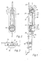
- FIG. 1 shows a rod lock 10 which locks the door 16 to the door frame 36 with the aid of rods 28, 30, the rods near the ends being guided in a suitable manner, for example by means of rod guides 40 on the door 16 .
- FIGS. 2 and 3 show a front view and a view play from above on the closure of FIG. 1.
- the closing part 12 of the closure 10 is of relatively simple construction and essentially consists of an actuating shaft 14 leading through the door leaf 16, which is rotatably mounted in a bearing housing 18 through at least 90 °, wherein the rotation angle limitation is effected, for example, by means of a nose (not shown in more detail) at the inner end of the actuating shaft 14, which strikes against stop surfaces 20, 22 of the bearing housing 18.
- This inner end of the actuating shaft 14 also carries a double-armed lever 24, at the free ends of which an actuating rod 28 or 30 is articulated.
- the lever 24 can merge into the cam 32 in one piece.
- the bearing housing 18 has an external thread 26 for a fastening nut 27 for screwing the housing 28 after the housing 16 has been pushed through a corresponding opening in the door leaf 16.
- a handle 38 in the form of a handle lever is articulated at the outward end of the actuating shaft 14 by means of a pin 34 such that the handle lever 38 can be pivoted about an axis perpendicular to the shaft axis.
- the bearing housing 18 also has an outwardly opening trough 42 with an approximately hemispherical profile, in which the appropriately hemispherical end surface of the handle 38 is suitably inserted. In this way, the handle 38 can be pivoted both about the axis of the pin 34 and rotated about the axis of the actuating shaft 14.
- a projection 44 which, in the closed position of the handle 38 shown in FIG. 1, points in the direction of the door leaf 16 and is received by an attachment 46 which is supported by a corresponding one. Breakthrough of the door leaf 16 extends inwards.
- This inwardly extending portion 45 of the '46 attachment has a circular outer cross-section and an external thread 48 on which a nut is attached Similar to the nut 27 or, as shown, a cup-like nut 50 provided with an internal thread can be screwed on, so that a gas, dust or moisture-tight closure of the opening in the door leaf 16 is obtained.
- the height of this cup nut 50 should not. be larger than the distance of the rod 28 from the door leaf 16 allows, because otherwise the attachment 46 could not be mounted in the region of the rod 28, as is the case with the embodiment according to FIGS. 1 to 3.
- the lower end of the handle 38 also has a receptacle 52 for a cylinder lock 54 or the like; whose locking finger 56, when closed by means of a cylinder key, comes into a path with a stop surface 58 which prevents the projection 44 from being pulled out of the attachment 46 in a known manner.
- FIGS. 1 to 3 it is expedient, in accordance with the embodiment shown in FIGS. 1 to 3, to provide a plate 60 which can be placed on the door leaf 16 and which at its one end, as shown in FIG. 1, ends in the bearing housing 18 and at its other end , the lower end merges into the attachment 46 in one piece.
- the plate 60 could be screwed onto the door leaf 16 by means of a countersunk screw or the like (not shown here) or else welded or glued on.
- the attachment of the plate 60 is effected by fixing the bearing housing 18 by means of a nut 27 on the one hand and the attachment 46 penetrating the door leaf level inwards by means of the cup nut 50 .
- the cup nut 50 forms a tight seal with the door leaf 16, because this prevents the passage of harmful gases, moisture and dust through the opening formed in the door leaf 16 for the attachment 46, and in fact applies that for both directions.
- This tight seal could be achieved, for example characterized in that the cups nut at least somewhat resilient plastic material is made of a in the edge region, wherein a resilient lip (not shown) for additional sealing of the still resting on the door leaf 1 6 rim of the cup nut 50 may have.
- FIG. 4 Another possibility would be the interposition of a sealing sheet 47, see FIG. 4, between the outer surface of the door sheet 16 and the contact surface of the plate 60, the sealing sheet 47 having the same hole pattern as the door sheet.
- the handle 38 and the plate 60 are made of plastic material because, for reasons of stability, the actuating shaft 14 and the cam tongue 32 (as well as the double-armed lever 24 with the rods 28, 30 attached to it) ) is made of metal and therefore, if the handle 38 were also made of (electrically conductive) metal, a carry-over path would again be available for dangerous electrical voltages to the outside.
- annular groove 62 for receiving a sealing ring as well as within the bearing housing 18 could be formed in the area of the door opening for the actuating shaft 14 within the plate 16 speaking groove for receiving an O-ring seal 64 may be provided.
- FIG. 4 shows, in a view similar to FIG. 1, another embodiment of the control cabinet door lock according to the invention, the lock 10 here having a somewhat more complicated shape with removable bars 28, 30, a bar lock relining 66 and a panic device 78.
- the relining 66 ensures secure storage of the closure 10 even in this heavier embodiment, while at the same time providing a sufficient distance for the closure 10 and thus the rods 28, 30 from the door leaf 16, which is expedient in view of the inwardly projecting attachment 46 .
- a similar relining is also shown in the embodiment shown in FIG. 5, however the relining 66 there is not fastened to the door leaf, for example, by means of special (not shown) screws or welds, but is held by the nut 27, which also supports the bearing housing 18 and so that the plate 60 of the closure according to the invention holds.
- the relining 66 is provided with a bracket plate 68 spanning the area of the bearing housing 18, which has a breakthrough similar to that of the door leaf 16 for the bearing housing 18, so that after the nut 27 is screwed on, the bracket plate 68 lies firmly on the door leaf 16 is coming. To increase the rigidity of the bracket plate 68, this can be bent perpendicularly away from the door leaf plane 16 on one side, see reference number 70.
- this fastening hole for a conventional sash lock was already provided in the manufacture of the door leaf.
- this fastening hole is provided with at least one, usually four tendon-like constrictions to which the outer circumference of the push-through part of the closure is adapted.
- FIGS. 4 and 5 show very clearly the panic device which serves to be able to open the closure 10 even from the inside when the closure is locked from the outside by inserting the projection 44 into the attachment 46, so that someone accidentally locked in a walk-in cabinet can free themselves again. He can do this by actuating a lever 72 which is mounted on a square actuating shaft 74 projecting from the closure part 10 in a rotationally rigid manner.
- This actuating shaft 74 directly actuates the rod lock 10 with the rods 28, 30 and the sash and exits on the other side of the lock box 10 in order to open there in a freewheel device 80, consisting, for example, of a first one with the square Actuating shaft 74 torsionally rigid coupling disc 82 and a second with the actuating shaft 14 for the handle 38 rigidly connected second coupling disc 84.
- one coupling disc 80 is provided with one or two projections which engage in corresponding guide grooves in the other coupling disc with limited angular extent, can achieve that the two discs 80, 84 are mutually displaceable, for example, by about 90 °, such that the rod lock 10 can be opened and closed by means of the lever 72 without the actuating shaft 14 of the handle 38 having to rotate. On the other hand, it can be twisted. of the handle 38 to be closed, for example, 180 ° (at a clearance angle of 90 0) is also the closure 10 and opened.
- a normal metal nut similar to the nut 27 can also be used for fastening the depression 45, provided that the projection 44 is one of them Cylinder lock 54 receives cup-shaped enclosing shape.
- a lateral slot-shaped opening in the cup-like projection 44 would then have to be provided for the thumb 49 (see FIG. 4) of the cylinder lock, so that the thumb 49 can pass through and swivel into the closure track 58 (FIG. 1) of the attachment 49 and lock the lever 38.
- the (metallic) thumb 49 is covered in an insulating manner by the depression 45 of the attachment 46. However, the slot causes a leak.
- the retractable closure described above is particularly advantageous for sheet metal doors when it comes down to the cheap two-hole fastening and the tightness. It is of secondary importance whether a cylinder key is used for locking (as shown) or the square, triangular and similar keys that are also used with the normal cam locks.
- the lock In the case of plastic cabinets for electrical systems, the lock should be insulated in the manner described, since the lock cannot be grounded via the door leaf, which is made of insulating material, and a special grounding device is too expensive.
- the closure according to the invention thus allows not only a stable and non-rotatable two-hole fastening, but also a seal without complex additives and also a protective insulation of the closure against e.g. wires that are torn loose inside the control cabinet.
- a handle lever 38 which is in the rest position at all sides partially enclosing edge or a recess receiving at least part of the handle lever 38
- the overall height is also lower and Handle lever in the rest position does not offer any surface for violent opening.
Landscapes
- Engineering & Computer Science (AREA)
- Mechanical Engineering (AREA)
- Patch Boards (AREA)
- Lock And Its Accessories (AREA)
Priority Applications (1)
| Application Number | Priority Date | Filing Date | Title |
|---|---|---|---|
| AT81110099T ATE9830T1 (de) | 1980-12-06 | 1981-12-03 | Versenkbarer verschluss fuer schaltschranktueren o. dgl. |
Applications Claiming Priority (2)
| Application Number | Priority Date | Filing Date | Title |
|---|---|---|---|
| DE3046150 | 1980-12-06 | ||
| DE19803046150 DE3046150A1 (de) | 1980-12-06 | 1980-12-06 | Versenkbarer verschluss fuer schaltschranktueren o.dgl. |
Publications (2)
| Publication Number | Publication Date |
|---|---|
| EP0054225A1 true EP0054225A1 (fr) | 1982-06-23 |
| EP0054225B1 EP0054225B1 (fr) | 1984-10-10 |
Family
ID=6118571
Family Applications (1)
| Application Number | Title | Priority Date | Filing Date |
|---|---|---|---|
| EP81110099A Expired EP0054225B1 (fr) | 1980-12-06 | 1981-12-03 | Serrure encastrée pour boîtes de commutation ou similaires |
Country Status (3)
| Country | Link |
|---|---|
| EP (1) | EP0054225B1 (fr) |
| AT (1) | ATE9830T1 (fr) |
| DE (2) | DE3046150A1 (fr) |
Cited By (12)
| Publication number | Priority date | Publication date | Assignee | Title |
|---|---|---|---|---|
| DE3310004A1 (de) * | 1983-03-19 | 1984-09-20 | Dieter 5620 Velbert Ramsauer | Panikeinrichtung zum oeffnen eines versenkbaren verschlusses |
| DE3812370C1 (en) * | 1988-04-14 | 1989-10-05 | Christian Geyer Gmbh & Co, 8500 Nuernberg, De | Electrical distribution cabinet, especially a cable distribution cabinet |
| WO1995029314A1 (fr) * | 1994-04-20 | 1995-11-02 | Emka Beschlagteile Gmbh & Co. Kg | Systeme de fermeture a serrure interieure variable |
| EP0699600A1 (fr) | 1994-08-25 | 1996-03-06 | EMKA BESCHLAGTEILE GmbH & Co. KG | Poubelle à verrouillage |
| DE19748878A1 (de) * | 1997-11-06 | 1999-05-20 | Ebe Elektro Bau Elemente Gmbh | Zylinderschloß zum Verriegeln insbesondere eines Drehgriffs insbesondere der Tür eines Elektroverteilerschrankes oder dergleichen |
| WO1999031338A1 (fr) * | 1997-12-15 | 1999-06-24 | Dieter Ramsauer | Fermeture a levier pivotant pour la porte, la paroi laterale ou similaire d'une armoire electrique, d'un capotage de machine ou analogue |
| EP1045098A1 (fr) | 1999-04-16 | 2000-10-18 | EMKA BESCHLAGTEILE GmbH & Co. KG | Crémone à tige ronde |
| EP1063370A1 (fr) * | 1999-06-05 | 2000-12-27 | Dieter Ramsauer | Serrure à levier pivotant |
| FR2796096A1 (fr) * | 1999-07-05 | 2001-01-12 | Socomec Sa | Dispositif de verrouillage d'une porte |
| WO2001079629A1 (fr) * | 2000-04-14 | 2001-10-25 | Dieter Ramsauer | Verrou destine a etre monte dans une ouverture pratiquee dans une paroi mince |
| DE202007014504U1 (de) | 2007-10-17 | 2009-03-05 | Ramsauer, Dieter | Stangenverschluss mit hebelförmigem Stangenantrieb |
| EP2653636A3 (fr) * | 2012-04-19 | 2016-12-28 | EMKA BESCHLAGTEILE GmbH & Co. KG | Fermeture à levier pivotant avec d'un levier pivotant installé pour une utilisation avec des moyens de verrouillage variable |
Families Citing this family (10)
| Publication number | Priority date | Publication date | Assignee | Title |
|---|---|---|---|---|
| DE3101009A1 (de) * | 1981-01-15 | 1982-08-05 | Dieter 5620 Velbert Ramsauer | Panik-verschlusseinrichtung |
| DE3243029C3 (de) * | 1982-11-20 | 1998-01-29 | Dieter Ramsauer | Versenkbarer Verschluß für Schaltschranktüren |
| DE3431358A1 (de) * | 1984-08-25 | 1986-03-06 | Dieter 5620 Velbert Ramsauer | Versenkbarer verschluss fuer schaltschranktueren |
| AT384063B (de) * | 1986-01-23 | 1987-09-25 | Assmann Geb | Schwenkhebelverschluss |
| EP0261267B2 (fr) * | 1986-09-25 | 1999-12-15 | Dieter Ramsauer | Fermeture de barre pour portes d'armoires en tÔle |
| EP0261266B1 (fr) * | 1986-09-25 | 1990-08-22 | Dieter Ramsauer | Fermeture par tringles à poignée basculante |
| DE4013439A1 (de) * | 1990-04-27 | 1991-10-31 | Emka Beschlagteile | Mit schlosseinrichtung versehener versenkbarer schwenkhebelverschluss |
| DE9015597U1 (de) * | 1990-11-14 | 1992-03-19 | Ramsauer, Dieter, 5620 Velbert | Stangenverschluß mit lösbarer Stangenverbindung |
| DE4117199C2 (de) * | 1991-05-27 | 2002-06-06 | Emka Beschlagteile | Abdeck- und/oder Befestigungskappe aus Kunststoff für einen in Durchbrüche in einer dünnen Wand, wie Blechschranktürblatt, einbringbaren Verschluß |
| JPH0717203Y2 (ja) * | 1993-03-18 | 1995-04-19 | タキゲン製造株式会社 | 平面ハンドル装置 |
Citations (3)
| Publication number | Priority date | Publication date | Assignee | Title |
|---|---|---|---|---|
| US2246708A (en) * | 1940-09-11 | 1941-06-24 | Glenn L Martin Co | Flush door handle and lock |
| US2377301A (en) * | 1943-05-01 | 1945-05-29 | Yale & Towne Mfg Co | Door lock |
| US3745796A (en) * | 1971-08-30 | 1973-07-17 | Fleming Metal Fabricators | Lock assembly for metal box |
Family Cites Families (1)
| Publication number | Priority date | Publication date | Assignee | Title |
|---|---|---|---|---|
| DE7014950U (de) * | 1900-01-01 | F Driescher Elektrobedarf | Betätigungsgriff für Türvercschlüsse |
-
1980
- 1980-12-06 DE DE19803046150 patent/DE3046150A1/de not_active Withdrawn
-
1981
- 1981-12-03 EP EP81110099A patent/EP0054225B1/fr not_active Expired
- 1981-12-03 DE DE8181110099T patent/DE3166636D1/de not_active Expired
- 1981-12-03 AT AT81110099T patent/ATE9830T1/de not_active IP Right Cessation
Patent Citations (3)
| Publication number | Priority date | Publication date | Assignee | Title |
|---|---|---|---|---|
| US2246708A (en) * | 1940-09-11 | 1941-06-24 | Glenn L Martin Co | Flush door handle and lock |
| US2377301A (en) * | 1943-05-01 | 1945-05-29 | Yale & Towne Mfg Co | Door lock |
| US3745796A (en) * | 1971-08-30 | 1973-07-17 | Fleming Metal Fabricators | Lock assembly for metal box |
Cited By (14)
| Publication number | Priority date | Publication date | Assignee | Title |
|---|---|---|---|---|
| DE3310004A1 (de) * | 1983-03-19 | 1984-09-20 | Dieter 5620 Velbert Ramsauer | Panikeinrichtung zum oeffnen eines versenkbaren verschlusses |
| DE3812370C1 (en) * | 1988-04-14 | 1989-10-05 | Christian Geyer Gmbh & Co, 8500 Nuernberg, De | Electrical distribution cabinet, especially a cable distribution cabinet |
| WO1995029314A1 (fr) * | 1994-04-20 | 1995-11-02 | Emka Beschlagteile Gmbh & Co. Kg | Systeme de fermeture a serrure interieure variable |
| EP0699600A1 (fr) | 1994-08-25 | 1996-03-06 | EMKA BESCHLAGTEILE GmbH & Co. KG | Poubelle à verrouillage |
| DE19748878C2 (de) * | 1997-11-06 | 2002-01-17 | Ebe Elektro Bau Elemente Gmbh | Vorreiberverschluss insbesondere für Schaltschranktüren |
| DE19748878A1 (de) * | 1997-11-06 | 1999-05-20 | Ebe Elektro Bau Elemente Gmbh | Zylinderschloß zum Verriegeln insbesondere eines Drehgriffs insbesondere der Tür eines Elektroverteilerschrankes oder dergleichen |
| WO1999031338A1 (fr) * | 1997-12-15 | 1999-06-24 | Dieter Ramsauer | Fermeture a levier pivotant pour la porte, la paroi laterale ou similaire d'une armoire electrique, d'un capotage de machine ou analogue |
| EP1045098A1 (fr) | 1999-04-16 | 2000-10-18 | EMKA BESCHLAGTEILE GmbH & Co. KG | Crémone à tige ronde |
| EP1063370A1 (fr) * | 1999-06-05 | 2000-12-27 | Dieter Ramsauer | Serrure à levier pivotant |
| FR2796096A1 (fr) * | 1999-07-05 | 2001-01-12 | Socomec Sa | Dispositif de verrouillage d'une porte |
| WO2001079629A1 (fr) * | 2000-04-14 | 2001-10-25 | Dieter Ramsauer | Verrou destine a etre monte dans une ouverture pratiquee dans une paroi mince |
| US6840552B2 (en) | 2000-04-14 | 2005-01-11 | Dieter Ramsauer | Lock for assembly in an opening in a thin wall |
| DE202007014504U1 (de) | 2007-10-17 | 2009-03-05 | Ramsauer, Dieter | Stangenverschluss mit hebelförmigem Stangenantrieb |
| EP2653636A3 (fr) * | 2012-04-19 | 2016-12-28 | EMKA BESCHLAGTEILE GmbH & Co. KG | Fermeture à levier pivotant avec d'un levier pivotant installé pour une utilisation avec des moyens de verrouillage variable |
Also Published As
| Publication number | Publication date |
|---|---|
| DE3046150A1 (de) | 1982-07-22 |
| ATE9830T1 (de) | 1984-10-15 |
| EP0054225B1 (fr) | 1984-10-10 |
| DE3166636D1 (en) | 1984-11-15 |
Similar Documents
| Publication | Publication Date | Title |
|---|---|---|
| EP0054225B1 (fr) | Serrure encastrée pour boîtes de commutation ou similaires | |
| DE3812972C1 (fr) | ||
| DE19914568C2 (de) | Magnetbetätigbarer Melder mit Reed-Kontakt | |
| EP0123788A2 (fr) | Appareil d'installation électrique | |
| EP0635612B1 (fr) | Dispositif de verrouillage pour porte | |
| EP0862252B1 (fr) | Armoire pour composants électriques et électroniques | |
| DE3943377C1 (en) | Locking closure for electrical switching appts. housing - has arresting nose on cover engaging recess in housing and locking part arresting snap coupling | |
| DE19815602C2 (de) | Befestigungssystem zum Befestigen einer Platte innerhalb eines Gehäuses | |
| DE3101009C2 (fr) | ||
| DE8032588U1 (de) | Versenkbarer Verschluß für Schaltschranktüren o.dgl. | |
| EP0453626B1 (fr) | Dispositif de fermeture de levier pivotant et enfonçant muni d'une serrure | |
| EP0143263B1 (fr) | Interrupteur à clé | |
| EP3869645B1 (fr) | Couvercle de protection contre la manipulation d'un appareil de protection contre les surtensions destiné à l'installation sur un système de barre omnibus | |
| DE3639670C2 (de) | Einrichtung zum Plombieren und gleichzeitigen mechanischen Verriegeln eines Deckels an einem Gerät | |
| DE10226634B3 (de) | Elektroinstallationsvorrichtung, insbesondere für einen Zählerschrank | |
| DE9004755U1 (de) | Mit Schloßeinrichtung versehener versenkbarer Schwenkhebelverschluß | |
| DE3738907C2 (fr) | ||
| DE19825242B4 (de) | Elektrisches Installationsgerät | |
| EP0680123B1 (fr) | Armoire de commutation pour installation électrique | |
| DE202024100717U1 (de) | Zähler- und Verteilerschrank | |
| DE19830139B4 (de) | Schlüsselschaltervorrichtung | |
| DE3522826C2 (fr) | ||
| DE19826815C2 (de) | Verschlußeinrichtung an Öffnungen für Taster und/oder Leuchten in Deckelplatten von elektrischen und elektronischen Geräten | |
| DE19814784C2 (de) | Schaltsperre gegen unbefugtes Schalten eines elektrischen Installationsgerätes | |
| DE9108297U1 (de) | Adaptertafel für elektrische Installationseinrichtungen |
Legal Events
| Date | Code | Title | Description |
|---|---|---|---|
| PUAI | Public reference made under article 153(3) epc to a published international application that has entered the european phase |
Free format text: ORIGINAL CODE: 0009012 |
|
| AK | Designated contracting states |
Designated state(s): AT BE CH DE FR GB IT LU NL SE |
|
| 17P | Request for examination filed |
Effective date: 19820726 |
|
| ITF | It: translation for a ep patent filed | ||
| GRAA | (expected) grant |
Free format text: ORIGINAL CODE: 0009210 |
|
| AK | Designated contracting states |
Designated state(s): AT BE CH DE FR GB IT LI LU NL SE |
|
| PG25 | Lapsed in a contracting state [announced via postgrant information from national office to epo] |
Ref country code: NL Effective date: 19841010 Ref country code: BE Effective date: 19841010 |
|
| REF | Corresponds to: |
Ref document number: 9830 Country of ref document: AT Date of ref document: 19841015 Kind code of ref document: T |
|
| REF | Corresponds to: |
Ref document number: 3166636 Country of ref document: DE Date of ref document: 19841115 |
|
| PG25 | Lapsed in a contracting state [announced via postgrant information from national office to epo] |
Ref country code: AT Effective date: 19841203 |
|
| PG25 | Lapsed in a contracting state [announced via postgrant information from national office to epo] |
Ref country code: LU Free format text: LAPSE BECAUSE OF NON-PAYMENT OF DUE FEES Effective date: 19841231 Ref country code: LI Effective date: 19841231 Ref country code: CH Effective date: 19841231 |
|
| ET | Fr: translation filed | ||
| NLV1 | Nl: lapsed or annulled due to failure to fulfill the requirements of art. 29p and 29m of the patents act | ||
| PLBI | Opposition filed |
Free format text: ORIGINAL CODE: 0009260 |
|
| REG | Reference to a national code |
Ref country code: CH Ref legal event code: PL |
|
| 26 | Opposition filed |
Opponent name: EMKA INDUSTRILAS AB Effective date: 19850629 |
|
| PLBI | Opposition filed |
Free format text: ORIGINAL CODE: 0009260 |
|
| 26 | Opposition filed |
Opponent name: STEINBACH & VOLLMANN GMBH & CO. Effective date: 19860627 |
|
| ITTA | It: last paid annual fee | ||
| PLBI | Opposition filed |
Free format text: ORIGINAL CODE: 0009260 |
|
| 26 | Opposition filed |
Opponent name: EMKA BESCHLAGTEILE GMBH & CO. KG Effective date: 19920226 Opponent name: STEINBACH & VOLLMANN GMBH & CO. Effective date: 19860627 Opponent name: EMKA INDUSTRILAS AB Effective date: 19850629 |
|
| PLBN | Opposition rejected |
Free format text: ORIGINAL CODE: 0009273 |
|
| STAA | Information on the status of an ep patent application or granted ep patent |
Free format text: STATUS: OPPOSITION REJECTED |
|
| 27O | Opposition rejected |
Effective date: 19930327 |
|
| EAL | Se: european patent in force in sweden |
Ref document number: 81110099.9 |
|
| PGFP | Annual fee paid to national office [announced via postgrant information from national office to epo] |
Ref country code: SE Payment date: 19991217 Year of fee payment: 19 |
|
| PGFP | Annual fee paid to national office [announced via postgrant information from national office to epo] |
Ref country code: FR Payment date: 20001124 Year of fee payment: 20 |
|
| PGFP | Annual fee paid to national office [announced via postgrant information from national office to epo] |
Ref country code: GB Payment date: 20001127 Year of fee payment: 20 |
|
| PG25 | Lapsed in a contracting state [announced via postgrant information from national office to epo] |
Ref country code: SE Free format text: LAPSE BECAUSE OF NON-PAYMENT OF DUE FEES Effective date: 20001204 |
|
| PGFP | Annual fee paid to national office [announced via postgrant information from national office to epo] |
Ref country code: DE Payment date: 20010201 Year of fee payment: 20 |
|
| EUG | Se: european patent has lapsed |
Ref document number: 81110099.9 |
|
| PG25 | Lapsed in a contracting state [announced via postgrant information from national office to epo] |
Ref country code: GB Free format text: LAPSE BECAUSE OF EXPIRATION OF PROTECTION Effective date: 20011202 |
|
| REG | Reference to a national code |
Ref country code: GB Ref legal event code: PE20 Effective date: 20011202 |
|
| APAH | Appeal reference modified |
Free format text: ORIGINAL CODE: EPIDOSCREFNO |