EP0055101A2 - Vorrichtung und Verfahren zum hydraulischen Formen von Verbindungen zwischen Rohren und Rohrplatten - Google Patents
Vorrichtung und Verfahren zum hydraulischen Formen von Verbindungen zwischen Rohren und Rohrplatten Download PDFInfo
- Publication number
- EP0055101A2 EP0055101A2 EP81305963A EP81305963A EP0055101A2 EP 0055101 A2 EP0055101 A2 EP 0055101A2 EP 81305963 A EP81305963 A EP 81305963A EP 81305963 A EP81305963 A EP 81305963A EP 0055101 A2 EP0055101 A2 EP 0055101A2
- Authority
- EP
- European Patent Office
- Prior art keywords
- tube
- seal member
- mandrel body
- ramp
- mandrel
- Prior art date
- Legal status (The legal status is an assumption and is not a legal conclusion. Google has not performed a legal analysis and makes no representation as to the accuracy of the status listed.)
- Granted
Links
Images
Classifications
-
- B—PERFORMING OPERATIONS; TRANSPORTING
- B21—MECHANICAL METAL-WORKING WITHOUT ESSENTIALLY REMOVING MATERIAL; PUNCHING METAL
- B21D—WORKING OR PROCESSING OF SHEET METAL OR METAL TUBES, RODS OR PROFILES WITHOUT ESSENTIALLY REMOVING MATERIAL; PUNCHING METAL
- B21D39/00—Application of procedures in order to connect objects or parts, e.g. coating with sheet metal otherwise than by plating; Tube expanders
- B21D39/06—Application of procedures in order to connect objects or parts, e.g. coating with sheet metal otherwise than by plating; Tube expanders of tubes in openings, e.g. rolling-in
-
- B—PERFORMING OPERATIONS; TRANSPORTING
- B21—MECHANICAL METAL-WORKING WITHOUT ESSENTIALLY REMOVING MATERIAL; PUNCHING METAL
- B21D—WORKING OR PROCESSING OF SHEET METAL OR METAL TUBES, RODS OR PROFILES WITHOUT ESSENTIALLY REMOVING MATERIAL; PUNCHING METAL
- B21D39/00—Application of procedures in order to connect objects or parts, e.g. coating with sheet metal otherwise than by plating; Tube expanders
- B21D39/08—Tube expanders
- B21D39/20—Tube expanders with mandrels, e.g. expandable
- B21D39/203—Tube expanders with mandrels, e.g. expandable expandable by fluid or elastic material
-
- Y—GENERAL TAGGING OF NEW TECHNOLOGICAL DEVELOPMENTS; GENERAL TAGGING OF CROSS-SECTIONAL TECHNOLOGIES SPANNING OVER SEVERAL SECTIONS OF THE IPC; TECHNICAL SUBJECTS COVERED BY FORMER USPC CROSS-REFERENCE ART COLLECTIONS [XRACs] AND DIGESTS
- Y10—TECHNICAL SUBJECTS COVERED BY FORMER USPC
- Y10T—TECHNICAL SUBJECTS COVERED BY FORMER US CLASSIFICATION
- Y10T29/00—Metal working
- Y10T29/49—Method of mechanical manufacture
- Y10T29/4935—Heat exchanger or boiler making
- Y10T29/49373—Tube joint and tube plate structure
- Y10T29/49375—Tube joint and tube plate structure including conduit expansion or inflation
-
- Y—GENERAL TAGGING OF NEW TECHNOLOGICAL DEVELOPMENTS; GENERAL TAGGING OF CROSS-SECTIONAL TECHNOLOGIES SPANNING OVER SEVERAL SECTIONS OF THE IPC; TECHNICAL SUBJECTS COVERED BY FORMER USPC CROSS-REFERENCE ART COLLECTIONS [XRACs] AND DIGESTS
- Y10—TECHNICAL SUBJECTS COVERED BY FORMER USPC
- Y10T—TECHNICAL SUBJECTS COVERED BY FORMER US CLASSIFICATION
- Y10T29/00—Metal working
- Y10T29/53—Means to assemble or disassemble
- Y10T29/53113—Heat exchanger
- Y10T29/53122—Heat exchanger including deforming means
Definitions
- the present invention relates to apparatus and methods for forming joins by the Hydraulic expansion of tubes within tube sheets to form leak-proof joints and, more particularly, to the use of hydraulic swaging forces to produce such expansion.
- Older techniques for expanding the tubes to form the desired leak-proof joints relied upon roller swaging.
- mechanical rolling of the interior surface of the tube causes a decrease in the thickness of the tube wall.
- roller swaging is a time-consuming process and it is sometimes difficult or impossible, particularly in the case of small diameter tubes, to obtain the swaging pressures desired.
- O-rings are usually used for the seals. In the case of high-pressure applications, it is desirable to use O-rings in combination with back-up members of a stiffer material such as polyurethane.
- O-rings employed in this environment must have a sufficient diameter and rigidity to effectively confine the hydraulic fluid in the desired manner.
- an O-ring of suitable size and properties and mounted on a mandrel When inserted in a tube it offers very high frictional resistance, binding against the interior tube surface. Insertion of the mandrel is therefore difficult and time-consuming.
- the difficulties attributable to frictional O-ring resistance to mandrel insertion is a major factor bearing upon the efficiency and effectiveness of hydraulic swaging techniques that have been employed.
- a principal objective of the present invention is to provide a swaging apparatus and. method for forming joints between tubes and tube sheets in which the resistance offered by the seals as the mandrel is inserted in the tube is greatly reduced, although the effectiveness of the seals is not diminished.
- the present invention relates to an apparatus and method that accomplishes the above objective by the use of ramps that permit a seal member to expand and contract radially while moving axially. This arrangement permits the seal member to be contracted for purposes of insertion of a mandrel.
- apparatus for' use in hydraulically expanding a tube
- the apparatus comprising a mandrel body which is insertable within the tube to be expanded, and means for cooperating with the mandrel body and the tube to define within the tube a volume to be expanded by hydraulically effected deformation of the tube, the mandrel body being adapted to allow pressurized hydraulic fluid to enter the defined volume and the said means including at least one seal member carried by the mandrel body and serving in operation to define one end of the said volume, characterised in that a ramp is provided which is defined by the mandrel body, tapers from substantially the said one end of the said volume towards the other end thereof and is such as to allow the said seal member to move in each direction therealong axially of the mandrel body, and in that the arrangement is such that or means are provided so that, during insertion of the mandrel body into the tube, the said seal member is carried at a position where it slides on the inner surface of the tube with reduced frictional force
- a method of hydraulically forming a join between a tube and a tube sheet comprising the steps of: positioning the tube coaxially in a bore in the tube sheet, inserting a mandrel body into the tube, defining a volume between the inner surface of the tube and the mandrel body, hydraulically pressuring the defined volume sufficiently to expand the volume by deforming the tube into sealing contact with the inner surface of the said bore, and releasing the hydraulic pressure, characterised in that the step of inserting the mandrel body into the tube includes carrying on the mandrel body at least one seal member disposed substantially at the foot of a respective ramp defined by the mandrel body whereby the said seal member slides on the inner surface of the tube with reduced friction, and the step of defining the said volume includes hydraulically so pressuring a volume bounded by the tube, the mandrel body, the said seal member and further sealing means as to drive the said seal member up the respective ramp to a position where the said seal member defines one
- a single mandrel employs two similar seal members, preferably O-rings, that define opposite ends of a volume in which pressurized hydraulic fluid flows between the mandrel and the tube to produce radial expansion of the tube.
- the seal member that is inserted first is referred to as the inner seal member, while the other seal member is referred to as the outer seal member.
- the ramps can be so arranged that they taper radially inwardly toward each other.
- the ramp that carries the inner seal member tapers radially inwardly toward a mandrel head through which hydraulic fluid can be supplied via a passage extending along the mandrel body.
- this inner seal member and ramp combination does not include any arrangement for biasing the seal member toward the larger end of the ramp and the seal member is freely movable except for frictional forces.
- the seal member should, however, be so constructed that when it is disposed at the smaller end of the ramp, it has a sufficient diameter to lightly engage the interior surface of the tube. Hydraulic fluid then will not flow past the seal member but will instead force the seal member to move up the ramp into tighter engagement with the tube as the pressure increases.
- the ramp is so arranged that its smaller end is inserted in the tube first.
- the corresponding seal member is, therefore, urged toward the larger end of the ramp and will tend to bind against the inner surface of the tube as in previously known mandrel construction.
- means are provided for urging the outer seal member toward the smaller end of the ramp.
- a preferred arrangement for urging the seal member toward the smaller end of the ramp employs a spring, which may be a coil spring, that surrounds the mandrel body and acts on the seal member through a sleeve that is axially slidable on the mandrel body.
- this back-up seal member can be carried on the outside of the sleeve by which the spring biasing force is transmitted.
- Another aspect of. the present invention relates to a method applicable to the use of the apparatus described above.
- the inner seal member is maintained at the smaller end of the corresponding ramp by frictional forces as the mandrel is inserted in the tube, the seal member being freely movable on the ramp except for frictional forces.
- the force of hydraulic fluids supplied through the mandrel is then relied upon to move the seal member toward the larger end of the ramp as the hydraulic fluid pressure increases.
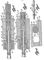
- a mandrel 10 shown in Figs. 1 to 4 of the accompanying drawings includes an elongate generally cylindrical mandrel body 12 and a head 14.
- the body 12 is inserted in a tube 16, as shown in Figs. 2 and 3, that is in turn positioned in a bore in a tube sheet 18.
- pressurized hydraulic fluid preferably water
- an axial passageway 20 in the mandrel body 12 that is continued by a cross-bore 22, permitting hydraulic fluid to enter an elongate annular volume 24 between the mandrel body 12 and the interior surface of the tube 16.
- the outer boundaries of this volume 24 are defined at opposite ends by an inner seal member 26 and an outer seal member 28, both seal members being O-rings that encircle the mandrel body 12.
- seal members 26 and 28 when in their operational positions shown in Fig. 3, are positioned on portions 30 and 32 of the mandrel body that are of reduced diameter. Adjacent to each of these reduced-diameter portions 30 and 32 is an inwardly tapered. conical ramp section 34 or 36.
- the inner seal 26 and corresponding ramp 34 will be considered first.
- This inner ramp 34 is tapered so that its diameter decreases in the direction of the outer seal 28 and the head 14.
- the inner seal 26 is freely movable on the ramp 34, except for frictional forces.
- the inner O-ring seal 26 is so dimensioned that when it is disposed at the smaller end of the ramp 34, its outside diameter is large enough to lightly engage the inner surface of the tube 16, as best shown in phantom lines in Fig. 4.
- hydraulic fluid enters the volume 24 it cannot readily pass the inner seal member 26 and the seal member is forced up the ramp 34 by the hydraulic pressure until it reaches the untapered reduced-diameter portion 30 of the mandrel body where it comes to rest, as shown in Fig. 3 and in solid lines in Fig. 4.
- the mandrel 10 is constructed to operate at an unusually high pressure at which the O-ring 26 could fail.
- An annular ring-shaped inner back-up member 38 is, therefore, provided which encircles the mandrel body 12 on the low pressure side of the O-ring 26.
- the back-up member 38 is made of polyurethane, and at high pressure, such as 206850kPa , it behaves as a liquid, although it retains a memory and returns to its original shape when the pressure is released.
- the back-up member 38 encircles and rides on a sleeve 40 that in turn is slidable on the mandrel body 12.
- the sleeve 40 includes a flange 42 on its leading edge that separates the O-ring seal member 26 from the back-up member 38.
- an abutment piece 44 At the opposite side of the back-up member 38 is an abutment piece 44 that positions the back-up member 38 and is undercut to permit limited axial movement of the sleeve 40.
- one function of the sleeve 40 is to ensure symmetrical radial expansion of the back-up member 38.
- the abutment piece 50 is slidable on the mandrel body 12 and is urged away from the head 14 by the spring 52.
- the force of the spring 52 is sufficient to overcome the frictional forces acting on the outer O-ring 28 and to retain that O-ring at the smaller end of the outer ramp 36.
- the outer O-ring 28 has a large enough outside diameter for it to lightly engage the interior surface of the tube 12.
- hydraulic fluid is introduced to the annular volume 24, that fluid cannot pass the outer O-ring 28. Instead, it overcomes the force of the spring 52 and moves the outer O-ring 28 axially along the mandrel body 10 to the larger end of the ramp 36.
- the 0-ring 28 then forms a tight leak-proof seal against the tube and transmits the force of the hydraulic fluid to the back-up member 46.
- the present invention provides a unique and improved mandrel which can be readily inserted in a tube without the need to overcome large frictional forces. Nevertheless, the effectiveness of the seals in containing the hydraulic fluid is not diminished.
Landscapes
- Engineering & Computer Science (AREA)
- Mechanical Engineering (AREA)
- Shaping Of Tube Ends By Bending Or Straightening (AREA)
- Joints With Sleeves (AREA)
Applications Claiming Priority (2)
| Application Number | Priority Date | Filing Date | Title |
|---|---|---|---|
| US06/218,431 US4414739A (en) | 1980-12-19 | 1980-12-19 | Apparatus for hydraulically forming joints between tubes and tube sheets |
| US218431 | 1980-12-19 |
Publications (3)
| Publication Number | Publication Date |
|---|---|
| EP0055101A2 true EP0055101A2 (de) | 1982-06-30 |
| EP0055101A3 EP0055101A3 (en) | 1983-05-18 |
| EP0055101B1 EP0055101B1 (de) | 1986-08-27 |
Family
ID=22815089
Family Applications (1)
| Application Number | Title | Priority Date | Filing Date |
|---|---|---|---|
| EP81305963A Expired EP0055101B1 (de) | 1980-12-19 | 1981-12-18 | Vorrichtung und Verfahren zum hydraulischen Formen von Verbindungen zwischen Rohren und Rohrplatten |
Country Status (4)
| Country | Link |
|---|---|
| US (1) | US4414739A (de) |
| EP (1) | EP0055101B1 (de) |
| CA (1) | CA1157689A (de) |
| DE (1) | DE3175238D1 (de) |
Cited By (5)
| Publication number | Priority date | Publication date | Assignee | Title |
|---|---|---|---|---|
| EP0148454A3 (en) * | 1983-12-30 | 1985-11-06 | Westinghouse Electric Corporation | Improved mandrel having an eddy current probe |
| EP0153670A3 (en) * | 1984-02-27 | 1986-05-07 | Westinghouse Electric Corporation | Hybrid expansion apparatus and process |
| EP0301425A1 (de) * | 1987-07-28 | 1989-02-01 | Emitec Gesellschaft für Emissionstechnologie mbH | Aufweitsonde mit aufspreizbaren Dichtungen |
| EP0307643A1 (de) * | 1987-09-01 | 1989-03-22 | Emitec Gesellschaft für Emissionstechnologie mbH | Sonde zum hydraulischen Aufweiten mit Zentriereinrichtung |
| EP0374726A3 (de) * | 1988-12-17 | 1991-01-09 | Emitec Gesellschaft für Emissionstechnologie mbH | Verfahren zum Einbringen und Ziehen |
Families Citing this family (25)
| Publication number | Priority date | Publication date | Assignee | Title |
|---|---|---|---|---|
| US4607426A (en) * | 1985-08-05 | 1986-08-26 | Haskel, Inc. | Swaging method and apparatus for axially extended expansion of tubes |
| US4654943A (en) * | 1986-02-24 | 1987-04-07 | Foster Wheeler Energy Corporation | Tube positioning tool and method for use |
| US6868906B1 (en) | 1994-10-14 | 2005-03-22 | Weatherford/Lamb, Inc. | Closed-loop conveyance systems for well servicing |
| GB9714651D0 (en) | 1997-07-12 | 1997-09-17 | Petroline Wellsystems Ltd | Downhole tubing |
| US6098717A (en) * | 1997-10-08 | 2000-08-08 | Formlock, Inc. | Method and apparatus for hanging tubulars in wells |
| GB9723031D0 (en) | 1997-11-01 | 1998-01-07 | Petroline Wellsystems Ltd | Downhole tubing location method |
| US5901594A (en) * | 1998-01-21 | 1999-05-11 | Hydropro, Inc. | High pressure expansion mandrel with cams engaging oppositely directed ends of an expandable segmented ring |
| WO2000037766A2 (en) | 1998-12-22 | 2000-06-29 | Weatherford/Lamb, Inc. | Procedures and equipment for profiling and jointing of pipes |
| DE69928007D1 (de) | 1998-12-22 | 2005-12-01 | Weatherford Lamb | Abdichtanordnung für futterrohr |
| GB0224807D0 (en) | 2002-10-25 | 2002-12-04 | Weatherford Lamb | Downhole filter |
| US7188687B2 (en) | 1998-12-22 | 2007-03-13 | Weatherford/Lamb, Inc. | Downhole filter |
| US6415863B1 (en) | 1999-03-04 | 2002-07-09 | Bestline Liner System, Inc. | Apparatus and method for hanging tubulars in wells |
| GB9921557D0 (en) | 1999-09-14 | 1999-11-17 | Petroline Wellsystems Ltd | Downhole apparatus |
| US6598678B1 (en) | 1999-12-22 | 2003-07-29 | Weatherford/Lamb, Inc. | Apparatus and methods for separating and joining tubulars in a wellbore |
| US6325148B1 (en) | 1999-12-22 | 2001-12-04 | Weatherford/Lamb, Inc. | Tools and methods for use with expandable tubulars |
| EP1278932B1 (de) | 2000-05-05 | 2006-02-22 | Weatherford/Lamb, Inc. | Vorrichtung und verfahren zur herstellung einer lateralbohrung |
| US6530574B1 (en) | 2000-10-06 | 2003-03-11 | Gary L. Bailey | Method and apparatus for expansion sealing concentric tubular structures |
| US7172027B2 (en) | 2001-05-15 | 2007-02-06 | Weatherford/Lamb, Inc. | Expanding tubing |
| US6732806B2 (en) | 2002-01-29 | 2004-05-11 | Weatherford/Lamb, Inc. | One trip expansion method and apparatus for use in a wellbore |
| US7308944B2 (en) * | 2003-10-07 | 2007-12-18 | Weatherford/Lamb, Inc. | Expander tool for use in a wellbore |
| CA2523106C (en) * | 2004-10-12 | 2011-12-06 | Weatherford/Lamb, Inc. | Methods and apparatus for manufacturing of expandable tubular |
| CA2617498C (en) * | 2005-07-22 | 2014-09-23 | Weatherford/Lamb, Inc. | Apparatus and methods for creation of down hole annular barrier |
| CA2555563C (en) | 2005-08-05 | 2009-03-31 | Weatherford/Lamb, Inc. | Apparatus and methods for creation of down hole annular barrier |
| US9468966B2 (en) | 2010-06-04 | 2016-10-18 | Hydropro, Inc. | System and method for radically expanding hollow cylindrical objects |
| CN119281948B (zh) * | 2024-12-12 | 2025-03-04 | 河南健悦智能制冷有限公司 | 一种铝管铝翅片蒸发器的生产设备 |
Family Cites Families (8)
| Publication number | Priority date | Publication date | Assignee | Title |
|---|---|---|---|---|
| US268918A (en) * | 1882-12-12 | Eighths to warren w | ||
| US2460580A (en) * | 1942-03-31 | 1949-02-01 | Sulzer Ag | Method and device for fixing and sealing tubes in a partition wall by use of fluid pressure |
| US2479702A (en) * | 1945-08-22 | 1949-08-23 | Weatherhead Co | Coupling |
| DE1939105U (de) | 1966-03-30 | 1966-05-26 | L E Toelle Nachf | Monatshoeschen. |
| DE1939105A1 (de) * | 1968-08-13 | 1970-02-19 | High Pressure Components Ltd | Verfahren und Vorrichtung zum seitlichen Aufweiten von Rohren |
| DE2131811A1 (de) | 1971-06-23 | 1972-12-28 | Siemens Elektrogeraete Gmbh | Vorrichtung zum Tiefziehen rohrfoermiger Werkstuecke |
| US3977068A (en) * | 1975-07-14 | 1976-08-31 | Balcke-Durr Aktiengesellschaft | Device and method for expansion-swaging tubes into the bores of a tube plate |
| US4125937A (en) * | 1977-06-28 | 1978-11-21 | Westinghouse Electric Corp. | Apparatus for hydraulically expanding a tube |
-
1980
- 1980-12-19 US US06/218,431 patent/US4414739A/en not_active Expired - Lifetime
-
1981
- 1981-06-23 CA CA000380378A patent/CA1157689A/en not_active Expired
- 1981-12-18 EP EP81305963A patent/EP0055101B1/de not_active Expired
- 1981-12-18 DE DE8181305963T patent/DE3175238D1/de not_active Expired
Cited By (5)
| Publication number | Priority date | Publication date | Assignee | Title |
|---|---|---|---|---|
| EP0148454A3 (en) * | 1983-12-30 | 1985-11-06 | Westinghouse Electric Corporation | Improved mandrel having an eddy current probe |
| EP0153670A3 (en) * | 1984-02-27 | 1986-05-07 | Westinghouse Electric Corporation | Hybrid expansion apparatus and process |
| EP0301425A1 (de) * | 1987-07-28 | 1989-02-01 | Emitec Gesellschaft für Emissionstechnologie mbH | Aufweitsonde mit aufspreizbaren Dichtungen |
| EP0307643A1 (de) * | 1987-09-01 | 1989-03-22 | Emitec Gesellschaft für Emissionstechnologie mbH | Sonde zum hydraulischen Aufweiten mit Zentriereinrichtung |
| EP0374726A3 (de) * | 1988-12-17 | 1991-01-09 | Emitec Gesellschaft für Emissionstechnologie mbH | Verfahren zum Einbringen und Ziehen |
Also Published As
| Publication number | Publication date |
|---|---|
| DE3175238D1 (en) | 1986-10-02 |
| EP0055101B1 (de) | 1986-08-27 |
| US4414739A (en) | 1983-11-15 |
| CA1157689A (en) | 1983-11-29 |
| EP0055101A3 (en) | 1983-05-18 |
Similar Documents
| Publication | Publication Date | Title |
|---|---|---|
| EP0055101A2 (de) | Vorrichtung und Verfahren zum hydraulischen Formen von Verbindungen zwischen Rohren und Rohrplatten | |
| US4450612A (en) | Swaging apparatus for radially expanding tubes to form joints | |
| US4467630A (en) | Hydraulic swaging seal construction | |
| US4567631A (en) | Method for installing tubes in tube sheets | |
| US5437310A (en) | Plug assembly | |
| US4422317A (en) | Apparatus and process for selectively expanding a tube | |
| US4195390A (en) | Apparatus and method for manipulation and sleeving of tubular members | |
| CA1047748A (en) | Method of securing a sleeve within a tube | |
| US4006619A (en) | Tube expander utilizing hydraulically actuated pistons | |
| US4382379A (en) | Leak detection apparatus and method for use with tube and tube sheet joints | |
| EP0120277A1 (de) | Pressmuffe für die Reparatur eines Rohres | |
| JPS58128241A (ja) | 管状構造体を半径方向に拡大するためのすえ込み装置 | |
| GB2074914A (en) | Method of joining a sleeve to a pipe | |
| US5832588A (en) | Tube fitting and assembly method | |
| JPH0148091B2 (de) | ||
| CA1326128C (en) | Method of apparatus for expanding and sealing a sleeve into a surrounding tube | |
| US4761981A (en) | Swaging apparatus for flaring and anchoring tubes | |
| JPH07256365A (ja) | 管状部材の半径方向拡張装置及び方法 | |
| RS51184B (sr) | Metod i alat za hladno sastavljanje prirubnica i spojnica sa cevi | |
| CA1176040A (en) | Method for installing tubes in a tube sheet | |
| US4694677A (en) | Elongated tube expander tool | |
| US4779333A (en) | Sleeve to tubesheet expander tool | |
| JPH02247402A (ja) | 蒸気発生器の管の密封プラグ | |
| US4420867A (en) | Method of pressure fitting a tube in a tube sheet | |
| US4776072A (en) | Process for extracting a section of a heat-exchanger tube |
Legal Events
| Date | Code | Title | Description |
|---|---|---|---|
| PUAI | Public reference made under article 153(3) epc to a published international application that has entered the european phase |
Free format text: ORIGINAL CODE: 0009012 |
|
| AK | Designated contracting states |
Designated state(s): BE CH DE FR GB IT LI NL SE |
|
| RAP1 | Party data changed (applicant data changed or rights of an application transferred) |
Owner name: HASKEL, INC. |
|
| PUAL | Search report despatched |
Free format text: ORIGINAL CODE: 0009013 |
|
| AK | Designated contracting states |
Designated state(s): BE CH DE FR GB IT LI NL SE |
|
| 17P | Request for examination filed |
Effective date: 19831025 |
|
| GRAA | (expected) grant |
Free format text: ORIGINAL CODE: 0009210 |
|
| AK | Designated contracting states |
Kind code of ref document: B1 Designated state(s): BE CH DE FR GB IT LI NL SE |
|
| PG25 | Lapsed in a contracting state [announced via postgrant information from national office to epo] |
Ref country code: LI Effective date: 19860827 Ref country code: CH Effective date: 19860827 Ref country code: BE Effective date: 19860827 |
|
| PG25 | Lapsed in a contracting state [announced via postgrant information from national office to epo] |
Ref country code: SE Effective date: 19860831 |
|
| REF | Corresponds to: |
Ref document number: 3175238 Country of ref document: DE Date of ref document: 19861002 |
|
| ET | Fr: translation filed | ||
| ITF | It: translation for a ep patent filed | ||
| REG | Reference to a national code |
Ref country code: CH Ref legal event code: PL |
|
| PLBE | No opposition filed within time limit |
Free format text: ORIGINAL CODE: 0009261 |
|
| STAA | Information on the status of an ep patent application or granted ep patent |
Free format text: STATUS: NO OPPOSITION FILED WITHIN TIME LIMIT |
|
| 26N | No opposition filed | ||
| ITTA | It: last paid annual fee | ||
| PGFP | Annual fee paid to national office [announced via postgrant information from national office to epo] |
Ref country code: NL Payment date: 19931231 Year of fee payment: 13 |
|
| PGFP | Annual fee paid to national office [announced via postgrant information from national office to epo] |
Ref country code: GB Payment date: 19941208 Year of fee payment: 14 Ref country code: DE Payment date: 19941208 Year of fee payment: 14 |
|
| PGFP | Annual fee paid to national office [announced via postgrant information from national office to epo] |
Ref country code: FR Payment date: 19941209 Year of fee payment: 14 |
|
| PG25 | Lapsed in a contracting state [announced via postgrant information from national office to epo] |
Ref country code: NL Effective date: 19950701 |
|
| NLV4 | Nl: lapsed or anulled due to non-payment of the annual fee |
Effective date: 19950701 |
|
| PG25 | Lapsed in a contracting state [announced via postgrant information from national office to epo] |
Ref country code: GB Effective date: 19951218 |
|
| GBPC | Gb: european patent ceased through non-payment of renewal fee |
Effective date: 19951218 |
|
| PG25 | Lapsed in a contracting state [announced via postgrant information from national office to epo] |
Ref country code: FR Effective date: 19960830 |
|
| PG25 | Lapsed in a contracting state [announced via postgrant information from national office to epo] |
Ref country code: DE Effective date: 19960903 |
|
| REG | Reference to a national code |
Ref country code: FR Ref legal event code: ST |