EP0055185A1 - Dispositif pour amortir les chocs entre une charge et un support flottant au moment de l'enlèvement de la charge - Google Patents
Dispositif pour amortir les chocs entre une charge et un support flottant au moment de l'enlèvement de la charge Download PDFInfo
- Publication number
- EP0055185A1 EP0055185A1 EP81402049A EP81402049A EP0055185A1 EP 0055185 A1 EP0055185 A1 EP 0055185A1 EP 81402049 A EP81402049 A EP 81402049A EP 81402049 A EP81402049 A EP 81402049A EP 0055185 A1 EP0055185 A1 EP 0055185A1
- Authority
- EP
- European Patent Office
- Prior art keywords
- load
- support
- floating support
- jacket
- casing
- Prior art date
- Legal status (The legal status is an assumption and is not a legal conclusion. Google has not performed a legal analysis and makes no representation as to the accuracy of the status listed.)
- Granted
Links
- 230000035939 shock Effects 0.000 title claims abstract description 13
- 238000013016 damping Methods 0.000 claims abstract description 10
- 230000002427 irreversible effect Effects 0.000 claims abstract description 4
- 239000006096 absorbing agent Substances 0.000 description 7
- XEEYBQQBJWHFJM-UHFFFAOYSA-N Iron Chemical compound [Fe] XEEYBQQBJWHFJM-UHFFFAOYSA-N 0.000 description 4
- 230000000694 effects Effects 0.000 description 2
- 229920001971 elastomer Polymers 0.000 description 2
- 239000000806 elastomer Substances 0.000 description 2
- 238000009434 installation Methods 0.000 description 2
- 229910052742 iron Inorganic materials 0.000 description 2
- 239000007787 solid Substances 0.000 description 2
- 239000004677 Nylon Substances 0.000 description 1
- 238000003032 molecular docking Methods 0.000 description 1
- 229920001778 nylon Polymers 0.000 description 1
Images


Classifications
-
- E—FIXED CONSTRUCTIONS
- E02—HYDRAULIC ENGINEERING; FOUNDATIONS; SOIL SHIFTING
- E02B—HYDRAULIC ENGINEERING
- E02B17/00—Artificial islands mounted on piles or like supports, e.g. platforms on raisable legs or offshore constructions; Construction methods therefor
- E02B17/02—Artificial islands mounted on piles or like supports, e.g. platforms on raisable legs or offshore constructions; Construction methods therefor placed by lowering the supporting construction to the bottom, e.g. with subsequent fixing thereto
- E02B17/021—Artificial islands mounted on piles or like supports, e.g. platforms on raisable legs or offshore constructions; Construction methods therefor placed by lowering the supporting construction to the bottom, e.g. with subsequent fixing thereto with relative movement between supporting construction and platform
- E02B17/024—Artificial islands mounted on piles or like supports, e.g. platforms on raisable legs or offshore constructions; Construction methods therefor placed by lowering the supporting construction to the bottom, e.g. with subsequent fixing thereto with relative movement between supporting construction and platform shock absorbing means for the supporting construction
-
- B—PERFORMING OPERATIONS; TRANSPORTING
- B63—SHIPS OR OTHER WATERBORNE VESSELS; RELATED EQUIPMENT
- B63B—SHIPS OR OTHER WATERBORNE VESSELS; EQUIPMENT FOR SHIPPING
- B63B35/00—Vessels or similar floating structures specially adapted for specific purposes and not otherwise provided for
- B63B35/003—Vessels or similar floating structures specially adapted for specific purposes and not otherwise provided for for transporting very large loads, e.g. offshore structure modules
-
- B—PERFORMING OPERATIONS; TRANSPORTING
- B66—HOISTING; LIFTING; HAULING
- B66F—HOISTING, LIFTING, HAULING OR PUSHING, NOT OTHERWISE PROVIDED FOR, e.g. DEVICES WHICH APPLY A LIFTING OR PUSHING FORCE DIRECTLY TO THE SURFACE OF A LOAD
- B66F19/00—Hoisting, lifting, hauling or pushing, not otherwise provided for
Definitions
- the present invention relates to a device for absorbing shocks between a load and a floating support when removing the load from the floating support.
- the present invention aims to overcome these drawbacks and relates to a device for absorbing shocks between a load and a floating support, when removing the load from said support, said support comprising at least one wedging on which rests the load, characterized in that it comprises means for automatically inserting in an irreversible manner a damping member between the load and its fulcrum on the floating support as soon as the load is detached from the floating support.
- said means comprise a jacket having a bottom located upwards and disposed inside said casing and a damping member located inside said shirt and held against said bottom by means of a wedge having an inclined lower face and cooperating with a corner passing through said casing and said liner by slots made in the vertical walls of the liner and of the liner, the wedge being movable vertically inside the liner and said corner being subjected to a horizontal tensile force F , the upper face of the bottom of the shirt being at the top of the cabin during the transport of the load so that it rests on the cabin.
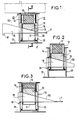
- the device according to the invention firstly comprises externally a casing 10 secured to a floating support 70 of a load 1.
- the casing 10 has on two of its faces massive parts 30. Inside this casing is disposed a jacket 11 comprising a cylindrical side wall 12 and a bottom 13 at the upper part of the side wall. At the bottom of the jacket 11 is placed a shock absorber 14, for example an elastomer block. Under this shock absorber, a wedge 15 with an inclined lower face 16 is placed. This wedge is placed at the bottom of a cylindrical box 17 which can slide vertically in the jacket 11 by more or less compressing the damper 14.
- a corner 18 with an inclined upper face 60 cooperates with the shim 15 and passes through the cabin 10, the jacket 11 and the box 17 by slots 19 made in the solid parts 30 of the cabin 10, 20 made in the jacket 11 and 21 practiced in the box 17.
- the corner 18 rests on the bottom 50 of the slots 19 made in the solid parts 30;
- the traction of the wedge 18 in the direction of the arrow F causes the rise of the wedge 15 and, in the absence of high weight on the top of the bottom 13 of the jacket 11, that of the damping member 14 and of the shirt 11 as seen in Figure 2.
- the stroke of the corner 18 is limited by a stop 61.
- the wedge 18 is in the position where it is shown in FIG. 1.
- the wedge 15 and the jacket 11 are in the low position, the assembly entered the cabin 10 and the load 1 rests on the cabin ( Figures 1 and 4).
- the jacket 11 is relieved of its weight and under the force exerted on the wedge 18 in the direction ' arrow F, the corner is moved which causes the rise of the shim 5 and with it, that of the damper 14 and the jacket 11.
- the support floating 70 rises under the effect of a wave top, and that the load has not yet been sufficiently high, the weight of the latter then compresses the damper 14 as seen in FIG. 3.
- the device makes it possible to automatically insert, and only when the load is removed, a damping device between the load and its floating support.
- shock absorber only appears during the very phase of removal of the load. It also removes any additional device for lifting the load on the floating support.
- the angle of the corner 18 is calculated taking into account the coefficient of friction and the force F so that the movement is irreversible whatever the load on the jacket 11.
- Figure 6 shows a particularly interesting application of the discharge of a marine platform from a transport barge and its installation on a fixed structure previously installed.
- the figure shows a platform 1 supported by a floating barge 2,
- the platform must be installed on a support structure comprising feet 3 which emerge and which include centering cones 40.
- the platform 2 is equipped with batteries 4 mobile thanks to a lifting system 5.
- the batteries have inside a damping device comprising a pin 6 bearing against a shock absorber 7 made of elastomer for example.
- a jack 8 associated with removable wedges 9 allows the final docking of the stacks 4 against the feet 3 and makes it possible to carry out the welds between stacks and feet while the load of the platform does not yet or entirely rest on the top of the feet but only on the centering cones 40 via the pinoche 6, the shock absorber 7 and the jack 8.
- This device is described in detail in the patent application filed today by the Applicant Company and having for title "Device for the establishment of a marine platform on its support structure".
- the device according to the invention A has been placed, described in detail in the preceding figures.
- the platform 1 is raised from the barge 2, by means of the machinery 5 which first of all lowers the stack 4 until the pinoche 6 makes contact with the centering cone 4, the effects of the swell being damped by the damper 7; at the same time, the shocks between the barge 2 and the platform 1, consecutive to a crest of swell succeeding a hollow during which the platform taking support on the feet 3 took off from the barge 2, are absorbed by to devices A according to the invention and described above.
Landscapes
- Engineering & Computer Science (AREA)
- Mechanical Engineering (AREA)
- Structural Engineering (AREA)
- General Engineering & Computer Science (AREA)
- Civil Engineering (AREA)
- Geology (AREA)
- Life Sciences & Earth Sciences (AREA)
- Transportation (AREA)
- Chemical & Material Sciences (AREA)
- Combustion & Propulsion (AREA)
- Ocean & Marine Engineering (AREA)
- Vibration Prevention Devices (AREA)
- Vibration Dampers (AREA)
- Carriers, Traveling Bodies, And Overhead Traveling Cranes (AREA)
Abstract
Description
- La présente invention concerne un dispositif pour amortir les chocs entre une charge et un support flottant au moment de l'enlèvement de la charge du support flottant.
- En effet, en présence de houle, pour des charges très importantes où la vitesse d'enlèvement ne peut pas être très rapide, on passe au moment de l'enlèvement par des phases critiques où la charge décolle de son support au moment d'un creux de houle et reprend contact avec lui au moment d'une crête. Pour éviter d'endommager le matériel, charge et support, il est donc nécessaire de prévoir un dispositif d'amortissement entre la charge et le support flottant.
- La nécessité d'une liaison rigide, non élastique, donc fer sur fer sans amortisseur pendant le transport a conduit à placer des systèmes amortisseurs au droit des points de supportage : les carlingages, mais juste seulement avant le déchargement. Une solution connue consiste donc à élever la charge à partir du support flottant de manière à pouvoir intercaler des systèmes amortisseurs. Cependant cette solution présente des inconvénients :
- En effet elle entraîne une phase, même si le déchargement est effectué immédiatement après, au cours de laquelle la charge repose élastiquement sur un support flottant, il peut donc y avoir des risques de résonance de la charge avec la houle. Il est nécessaire d'autre part de lever la charge à partir du support flottant pour ne pas retomber dans la difficulté que l'on veut résoudre, ce qui nécessite des moyens de levage importants, des points de supportage supplémentaires.......
- La présente invention a pour but de pallier ces inconvénients et a pour objet un dispositif pour amortir les chocs entre une charge et un support flottant, au moment de l'enlèvement de la charge dudit support, ledit support comportant au moins un calingage sur lequel repose la charge, caractérisé en ce qu'il comprend des moyens pour intercaler automatiquement d'une manière irréversible un organe amortisseur entre la charge et son point d'appui sur le support flottant dès le décollement de la charge du support flottant.
- Selon une réalisation particulière de la présente invention, lesdits moyens comprennent une chemise comportant un fond situé vers le haut et disposée à l'intérieur dudit carlingage et un organe amortisseur situé à l'intérieur de ladite chemise et maintenu contre ledit fond par l'intermédiaire d'une cale présentant une face inférieure inclinée et coopérant avec un coin traversant ledit carlingage et ladite chemise par des fentes réalisées dans les parois verticales du oarlingage et de la chemise, la cale étant mobile verticalement à l'intérieur de la chemise et ledit coin étant soumis à une force de traction horizontale F, la face supérieure du fond de la chemise étant au niveau du sommet du carlingage durant le transport de la charge de telle façon qu'elle repose sur le carlingage.
- L'invention sera bien comprise à la lumière de la description d'un exemple de réalisation du dispositif de l'invention, faite ci-après en regard du dessin annexé dans lequel :
- Les figures 1, 2 et 3 montrent le dispositif selon l'invention dans différentes positions.
- La figure 4 est une coupe selon IV-IV de la figure 1 en vue agrandie.
- La figure 5 est une coupe selon V-V de la figure 4.
- La figure 6 donne une présentation générale d'une application particulière de l'invention dans le cas particulièrement intéressant de l'enlèvement d'une plate-forme marine de sa barge de transport et de sa pose sur une structure fixe préalablement installée. La partie entourée A de cette figure étant détaillée dans les figures précédentes.
- En se référant aux figures 1, 4 et 5, le dispositif selon l'invention comporte d'abord extérieurement un carlingage 10 solidaire d'un support flottant 70 d'une charge 1.
- Le carlingage 10 possède sur deux de ses faces des pièces massives 30. A l'intérieur de ce carlingage est disposée une chemise 11 comportant une paroi latérale cylindrique 12 et un fond 13 à la partie supérieure de la paroi latérale. Au fond de la chemise 11 est placé un amortisseur de chocs 14 par exemple un bloc en élastomère. Sous cet amortisseur, est placée une cale 15 à face inférieure 16 inclinée. Cette cale est placée au fond d'une boite cylindrique 17 pouvant coulisser verticalement dans la chemise 11 en comprimant plus ou moins l'amortisseur 14.
- Un coin 18 à face supérieure 60 inclinée coopère avec la cale 15 et traverse le carlingage 10, la chemise 11 et la boîte 17 par des fentes 19 pratiquées dans les pièces massives 30 du carlingage 10, 20 pratiquées dans la chemise 11 et 21 pratiquées dans la boite 17. Le coin 18 repose sur le fond 50 des fentes 19 pratiquées dans les pièces massives 30; La traction du coin 18 dans le sens de la flèche F provoque la montée de la cale 15 et, en l'absence de poids élevé sur le sommet du fond 13 de la chemise 11, celle également de l'organe amortisseur 14 et de la chemise 11 comme on le voit sur la figure 2.
- L'effort de traction dans le sens de la flèche F peut être réalisé de toutes les façons : nylon tendu, poids suspendu sur les bords du support flottant avec poulie de renvoie......
- La course du coin 18 est limitée par une butée 61.
- Le fonctionnement du dispositif est le suivant, au cours du transport, le coin 18 se trouve dans la position où il est représenté sur la figure 1. Dans cette position, la cale 15 et la chemise 11 se trouvent en position basse, l'ensemble est rentré dans le carlingage 10 et la charge 1 repose sur le carlingage (figures 1 et 4). Au moment de l'enlèvement de la charge, lorsque celle-ci décolle du support flottant 70, par exemple dans un creux de vague, la chemise 11 est soulagée de son poids et sous l'effort exercé sur le coin 18 dans le sens'de la flèche F, le coin est déplacé ce qui provoque la montée de la cale 5 et avec elle, celle de l'amortisseur 14 et de la chemise 11. On obtient alors la position représentée sur la figure 2. Lorsque au contraire le support flottant 70 remonte sous l'effet d'un haut de vague, et que la charge n'ait pas encore été suffisamment élevée, le poids de celle-ci comprime alors l'amortisseur 14 tel qu'on le voit sur la figure 3.
- Dans ces deux figures 2 et 3, la charge 1 n'a pas été représentée mais bien entendu, elle repose sur le dispositif comme dans les figures 1 et 4.
- On voit donc que le dispositif permet d'intercaler automatiquement et seulement au moment de l'enlèvement de la charge, un dispositif amortisseur entre la charge et son support flottant.
- Il n'y a donc pas de période d'instabilité comme dans les dispositifs connus puisque l'amortisseur n'apparaît que durant la phase même de l'enlèvement de la charge. On supprime également tout dispositif annexe de levage de la charge sur le support flottant.
- Bien entendu l'angle du coin 18 est calculé compte tenu du coefficient de frottement et de la force F pour que le mouvement soit irréversible quelque soit la charge sur la chemise 11.
- La figure 6 représente une application particulièrement intéressante de la décharge d'une plate-forme marine d'une barge de transport et sa pose sur une struoture fixe préalablement installée.
- La figure montre une plate-forme 1 supportée par une barge flottante 2, La plate-forme doit être installée sur une structure support comportant des pieds 3 qui émergent et qui comprennent des cônes de centrage 40. La plate-forme 2 est équipée de piles 4 mobiles grâce à un système de levage 5. Les piles comportent en leur intérieur un dispositif d'amortissement comportant une pinoche 6 prenant appui contre un amortisseur 7 en élastomère par exemple. Un vérin 8 associé à des cales amovibles 9 permet l'accostage final des piles 4 contre les pieds 3 et permet de réaliser les soudures entre piles et pieds alors que la charge de la plate-forme ne repose pas encore ou pas en totalité sur le sommet des pieds mais seulement sur les cônes de centrage 40 par l'intermédiaire de la pinoche 6, de l'amortisseur 7 et du vérin 8. Ce dispositif est décrit en détail dans la demande de brevet déposé ce jour par la Société demanderesse et ayant pour titre " Dispositif pour la mise en place d'une plate-forme marine sur sa structure support".
- Entre la plate-forme 1 et la barge de transport 2 on a placé le dispositif selon l'invention A décrit en détail dans les figures précédentes. Ainsi, dans cette application la plate-forme 1 est soulevée de la barge 2, par l'intermédiaire de la machinerie 5 qui fait d'abord descendre la pile 4 jusqu'à la prise de contact de la pinoche 6 avec le cône de centrage 4, les effets de la houle étant amortis par l'amortisseur 7 ; en même temps, les chocs entre la barge 2 et la plate-forme 1, consécutifs à une crête de houle succédant à un creux au cours duquel la plate-forme prenant appui sur les pieds 3 a décollé de la barge 2, sont amortis grâce aux dispositifs A suivant l'invention et décrits plus haut.
Claims (2)
Applications Claiming Priority (2)
| Application Number | Priority Date | Filing Date | Title |
|---|---|---|---|
| FR8027348A FR2496624A1 (fr) | 1980-12-23 | 1980-12-23 | Dispositif pour amortir les chocs entre une charge et un support flottant au moment de l'enlevement de la charge |
| FR8027348 | 1980-12-23 |
Publications (2)
| Publication Number | Publication Date |
|---|---|
| EP0055185A1 true EP0055185A1 (fr) | 1982-06-30 |
| EP0055185B1 EP0055185B1 (fr) | 1984-08-29 |
Family
ID=9249416
Family Applications (1)
| Application Number | Title | Priority Date | Filing Date |
|---|---|---|---|
| EP81402049A Expired EP0055185B1 (fr) | 1980-12-23 | 1981-12-22 | Dispositif pour amortir les chocs entre une charge et un support flottant au moment de l'enlèvement de la charge |
Country Status (7)
| Country | Link |
|---|---|
| US (1) | US4408930A (fr) |
| EP (1) | EP0055185B1 (fr) |
| JP (1) | JPS57502009A (fr) |
| DE (1) | DE3165799D1 (fr) |
| FR (1) | FR2496624A1 (fr) |
| NO (1) | NO152803C (fr) |
| WO (1) | WO1982002220A1 (fr) |
Cited By (1)
| Publication number | Priority date | Publication date | Assignee | Title |
|---|---|---|---|---|
| CN107381448A (zh) * | 2017-06-08 | 2017-11-24 | 安徽机电职业技术学院 | 一种楔块推升式顶升机械 |
Families Citing this family (8)
| Publication number | Priority date | Publication date | Assignee | Title |
|---|---|---|---|---|
| US4744697A (en) * | 1985-04-29 | 1988-05-17 | Heerema Engineering Service Bv | Installation and removal vessel |
| US4655641A (en) * | 1985-10-18 | 1987-04-07 | Exxon Production Research Co. | Apparatus for aligning a platform deck and jacket |
| USH488H (en) | 1986-08-01 | 1988-07-05 | Hydraulic jacks for controlled load transfer | |
| GB2239280B (en) * | 1989-12-06 | 1993-06-23 | Marathon Oil Co | Motion absorbing docking assembly |
| US5035395A (en) * | 1989-12-15 | 1991-07-30 | Bigge Crane And Rigging Co. | Support cradle for load equalization |
| US5553977A (en) * | 1994-12-16 | 1996-09-10 | Northrop Grumman Corporation | Off-shore platform construction, and method for transferring loads |
| DE29716792U1 (de) * | 1997-09-18 | 1997-11-13 | Air-Loc Schrepfer AG, Küsnacht | Einrichtung zur Vergrößerung des Höheneinstellbereichs in einem Nivellierschuh und mit dieser versehener Nivellierschuh |
| NL2014042B1 (en) * | 2014-12-23 | 2016-10-12 | Heerema Marine Contractors Nl | Support device configured to be positioned on a lifting vessel in order to lift a topside from its support structure. |
Citations (11)
| Publication number | Priority date | Publication date | Assignee | Title |
|---|---|---|---|---|
| US2817212A (en) * | 1954-10-25 | 1957-12-24 | Frederick Snare Corp | Method for erecting and dismantling support structure |
| US2881590A (en) * | 1955-12-16 | 1959-04-14 | Shell Oil Co | Loading apparatus |
| FR1463297A (fr) * | 1965-01-08 | 1966-12-23 | Werf Gusto V H A F Smulders Fa | Plate-forme de forage ou similaire |
| US3376031A (en) * | 1965-10-19 | 1968-04-02 | Destech Labs Inc | Shock absorber |
| FR2224395A1 (fr) * | 1973-04-04 | 1974-10-31 | Westinghouse Electric Corp | |
| NL7400716A (en) * | 1974-01-18 | 1975-07-22 | Hattum & Blankevoort Bv | Shock absorber for off-shore oil well operating platform - with legs able to be lowered to the seabed |
| FR2312603A1 (fr) * | 1975-05-27 | 1976-12-24 | Levingston Shipbuilding Co | Dispositif compensateur de charges et amortisseur de chocs pour forage en mer |
| FR2383118A1 (fr) * | 1977-03-10 | 1978-10-06 | Metalliques Entrepr Cie Fse | Perfectionnements apportes aux ensembles du genre des plates-formes pour installations petrolieres sur fond marin ou autre, ou aux ensembles y assimilables |
| NL7801724A (en) * | 1978-02-15 | 1979-08-17 | Kens B V | Vessel for raising and conveying offshore platform - uses hydraulic jacks coupled to pressure accumulator to absorb shocks caused by impact |
| NL7804479A (en) * | 1978-04-26 | 1979-10-30 | Verolme Maschf Engineering Com | Mobile offshore drilling platform with retractable piles - has cushions between pile climbing mechanism and pontoon pressurised when pontoon is floating |
| GB2028404A (en) * | 1978-08-17 | 1980-03-05 | Goldman J L | Shock absorbing structure for off shore rigs |
Family Cites Families (7)
| Publication number | Priority date | Publication date | Assignee | Title |
|---|---|---|---|---|
| US2734739A (en) * | 1956-02-14 | Messina | ||
| US2262443A (en) * | 1940-06-29 | 1941-11-11 | Mathews Conveyer Co | Roller conveyer |
| FR1214760A (fr) * | 1958-02-03 | 1960-04-12 | Bataafsche Petroleum | Procédé pour enlever une plate-forme d'un dispositif à supports placé dans l'eauou pour l'y poser et installation pour exécuter ce procédé |
| US3606295A (en) * | 1968-11-12 | 1971-09-20 | Unilan Ag | Shock absorber |
| DE2432898C2 (de) * | 1974-07-09 | 1976-07-29 | Kober Ag | Gleitkipplager fur brucken od. ahnliche tragwerke |
| GB2022662B (en) | 1978-04-03 | 1982-04-21 | Brown & Root | Methods of and apparatus for forming offshore structures |
| JPS59165701U (ja) * | 1983-04-21 | 1984-11-07 | パイオニア株式会社 | 冷間圧延機 |
-
1980
- 1980-12-23 FR FR8027348A patent/FR2496624A1/fr active Granted
-
1981
- 1981-08-24 US US06/295,453 patent/US4408930A/en not_active Expired - Fee Related
- 1981-12-22 DE DE8181402049T patent/DE3165799D1/de not_active Expired
- 1981-12-22 EP EP81402049A patent/EP0055185B1/fr not_active Expired
- 1981-12-22 NO NO814408A patent/NO152803C/no unknown
- 1981-12-22 WO PCT/FR1981/000166 patent/WO1982002220A1/fr not_active Ceased
- 1981-12-22 JP JP57500219A patent/JPS57502009A/ja active Pending
Patent Citations (11)
| Publication number | Priority date | Publication date | Assignee | Title |
|---|---|---|---|---|
| US2817212A (en) * | 1954-10-25 | 1957-12-24 | Frederick Snare Corp | Method for erecting and dismantling support structure |
| US2881590A (en) * | 1955-12-16 | 1959-04-14 | Shell Oil Co | Loading apparatus |
| FR1463297A (fr) * | 1965-01-08 | 1966-12-23 | Werf Gusto V H A F Smulders Fa | Plate-forme de forage ou similaire |
| US3376031A (en) * | 1965-10-19 | 1968-04-02 | Destech Labs Inc | Shock absorber |
| FR2224395A1 (fr) * | 1973-04-04 | 1974-10-31 | Westinghouse Electric Corp | |
| NL7400716A (en) * | 1974-01-18 | 1975-07-22 | Hattum & Blankevoort Bv | Shock absorber for off-shore oil well operating platform - with legs able to be lowered to the seabed |
| FR2312603A1 (fr) * | 1975-05-27 | 1976-12-24 | Levingston Shipbuilding Co | Dispositif compensateur de charges et amortisseur de chocs pour forage en mer |
| FR2383118A1 (fr) * | 1977-03-10 | 1978-10-06 | Metalliques Entrepr Cie Fse | Perfectionnements apportes aux ensembles du genre des plates-formes pour installations petrolieres sur fond marin ou autre, ou aux ensembles y assimilables |
| NL7801724A (en) * | 1978-02-15 | 1979-08-17 | Kens B V | Vessel for raising and conveying offshore platform - uses hydraulic jacks coupled to pressure accumulator to absorb shocks caused by impact |
| NL7804479A (en) * | 1978-04-26 | 1979-10-30 | Verolme Maschf Engineering Com | Mobile offshore drilling platform with retractable piles - has cushions between pile climbing mechanism and pontoon pressurised when pontoon is floating |
| GB2028404A (en) * | 1978-08-17 | 1980-03-05 | Goldman J L | Shock absorbing structure for off shore rigs |
Cited By (1)
| Publication number | Priority date | Publication date | Assignee | Title |
|---|---|---|---|---|
| CN107381448A (zh) * | 2017-06-08 | 2017-11-24 | 安徽机电职业技术学院 | 一种楔块推升式顶升机械 |
Also Published As
| Publication number | Publication date |
|---|---|
| US4408930A (en) | 1983-10-11 |
| WO1982002220A1 (fr) | 1982-07-08 |
| NO152803C (no) | 1985-11-20 |
| EP0055185B1 (fr) | 1984-08-29 |
| FR2496624B1 (fr) | 1985-05-10 |
| NO152803B (no) | 1985-08-12 |
| FR2496624A1 (fr) | 1982-06-25 |
| DE3165799D1 (en) | 1984-10-04 |
| NO814408L (no) | 1982-06-24 |
| JPS57502009A (fr) | 1982-11-11 |
Similar Documents
| Publication | Publication Date | Title |
|---|---|---|
| EP0054914B1 (fr) | Dispositif pour la mise en place d'une plate-forme marine sur sa structure support | |
| EP0964102B1 (fr) | Dispositif de transport et de pose d'un pont d'une plate-forme pétrolière d'exploitation en mer | |
| EP0055185B1 (fr) | Dispositif pour amortir les chocs entre une charge et un support flottant au moment de l'enlèvement de la charge | |
| EP0065695B1 (fr) | Jambe d'une plate-forme marine et procédé de mise en place de la plate-forme | |
| EP0807081A1 (fr) | Separateur de charges pour couloir de stockage dynamique | |
| CA1074818A (fr) | Procede de transbordement de charges en mer et moyen de mise en oeuvre | |
| WO2011124854A1 (fr) | Dispositif de déclenchement d'avalanche | |
| FR2564811A1 (fr) | Caisse aspirante separatrice et/ou fournisseuse pour des dispositifs de separation et de fournitures pneumatiques de feuilles | |
| FR2829121A1 (fr) | Dispositif a plate-forme elevatrice pour conteneurs a ordures enterres | |
| EP0942102A1 (fr) | Plate-forme auto-élévatrice à réservoir immergé et procédés de mise en place et de relevage du réservoir | |
| EP0014661B1 (fr) | Dispositif pour l'installation d'un bloc formant réacteur nucléaire dans un navire | |
| EP0469212A1 (fr) | Dispositif permettant le déplacement vertical d'un lit à l'intérieur d'une structure | |
| EP0787870A1 (fr) | Dispositif de garage de véhicules à levage vertical | |
| CH675402A5 (fr) | ||
| FR2533898A1 (fr) | Dispositif de vidange automatique d'un recipient | |
| EP0001363B1 (fr) | Dispositif d'obturation de l'extrémité d'une conduite de remplissage de citerne | |
| FR2540218A1 (fr) | Soupape de decharge avec commande par difference de pression | |
| FR2539178A1 (fr) | Porte a commande par chaine a double securite | |
| FR1459994A (fr) | Perfectionnements aux bennes flottantes, notamment pour le ramassage des ordures dans les bassins portuaires | |
| FR2568862A1 (fr) | Dispositif pour le dechargement de materiaux divers dans les espaces entre les etages d'edifices en construction | |
| BE524626A (fr) | ||
| WO1991005722A1 (fr) | Dispositif polyvalent pour le relevage rapide de plaques de verre | |
| FR2829120A1 (fr) | Dispositif de plate-forme elevatrice autonome pour enterrer les conteneurs a ordures menageres | |
| EP3138104B1 (fr) | Dispositif d'ouverture et de fermeture d'un orifice au fond d'une piscine destinée à contenir du combustible irradié | |
| FR2464209A1 (fr) | Dispositif de chargement de sacs sur palettes |
Legal Events
| Date | Code | Title | Description |
|---|---|---|---|
| PUAI | Public reference made under article 153(3) epc to a published international application that has entered the european phase |
Free format text: ORIGINAL CODE: 0009012 |
|
| AK | Designated contracting states |
Designated state(s): DE FR GB IT NL |
|
| 17P | Request for examination filed |
Effective date: 19821130 |
|
| RAP1 | Party data changed (applicant data changed or rights of an application transferred) |
Owner name: ALSTHOM-ATLANTIQUE SOCIETE ANONYME DITE: |
|
| ITF | It: translation for a ep patent filed | ||
| GRAA | (expected) grant |
Free format text: ORIGINAL CODE: 0009210 |
|
| PGFP | Annual fee paid to national office [announced via postgrant information from national office to epo] |
Ref country code: FR Payment date: 19840810 Year of fee payment: 4 |
|
| PGFP | Annual fee paid to national office [announced via postgrant information from national office to epo] |
Ref country code: DE Payment date: 19840823 Year of fee payment: 4 |
|
| AK | Designated contracting states |
Designated state(s): DE FR GB IT NL |
|
| REF | Corresponds to: |
Ref document number: 3165799 Country of ref document: DE Date of ref document: 19841004 |
|
| PLBE | No opposition filed within time limit |
Free format text: ORIGINAL CODE: 0009261 |
|
| STAA | Information on the status of an ep patent application or granted ep patent |
Free format text: STATUS: NO OPPOSITION FILED WITHIN TIME LIMIT |
|
| 26N | No opposition filed | ||
| PGFP | Annual fee paid to national office [announced via postgrant information from national office to epo] |
Ref country code: NL Payment date: 19851231 Year of fee payment: 5 |
|
| PG25 | Lapsed in a contracting state [announced via postgrant information from national office to epo] |
Ref country code: NL Effective date: 19870701 |
|
| NLV4 | Nl: lapsed or anulled due to non-payment of the annual fee | ||
| PG25 | Lapsed in a contracting state [announced via postgrant information from national office to epo] |
Ref country code: DE Effective date: 19880901 |
|
| PG25 | Lapsed in a contracting state [announced via postgrant information from national office to epo] |
Ref country code: GB Effective date: 19881222 |
|
| GBPC | Gb: european patent ceased through non-payment of renewal fee | ||
| PG25 | Lapsed in a contracting state [announced via postgrant information from national office to epo] |
Ref country code: FR Free format text: LAPSE BECAUSE OF NON-PAYMENT OF DUE FEES Effective date: 19890831 |
|
| REG | Reference to a national code |
Ref country code: FR Ref legal event code: ST |