EP0055301B1 - Numerische steuereinheit - Google Patents
Numerische steuereinheit Download PDFInfo
- Publication number
- EP0055301B1 EP0055301B1 EP81901899A EP81901899A EP0055301B1 EP 0055301 B1 EP0055301 B1 EP 0055301B1 EP 81901899 A EP81901899 A EP 81901899A EP 81901899 A EP81901899 A EP 81901899A EP 0055301 B1 EP0055301 B1 EP 0055301B1
- Authority
- EP
- European Patent Office
- Prior art keywords
- numerical control
- control device
- standard numerical
- master
- standard
- Prior art date
- Legal status (The legal status is an assumption and is not a legal conclusion. Google has not performed a legal analysis and makes no representation as to the accuracy of the status listed.)
- Expired
Links
Images
Classifications
-
- G—PHYSICS
- G05—CONTROLLING; REGULATING
- G05B—CONTROL OR REGULATING SYSTEMS IN GENERAL; FUNCTIONAL ELEMENTS OF SUCH SYSTEMS; MONITORING OR TESTING ARRANGEMENTS FOR SUCH SYSTEMS OR ELEMENTS
- G05B19/00—Program-control systems
- G05B19/02—Program-control systems electric
- G05B19/418—Total factory control, i.e. centrally controlling a plurality of machines, e.g. direct or distributed numerical control [DNC], flexible manufacturing systems [FMS], integrated manufacturing systems [IMS] or computer integrated manufacturing [CIM]
- G05B19/4181—Total factory control, i.e. centrally controlling a plurality of machines, e.g. direct or distributed numerical control [DNC], flexible manufacturing systems [FMS], integrated manufacturing systems [IMS] or computer integrated manufacturing [CIM] characterised by direct numerical control [DNC]
-
- Y—GENERAL TAGGING OF NEW TECHNOLOGICAL DEVELOPMENTS; GENERAL TAGGING OF CROSS-SECTIONAL TECHNOLOGIES SPANNING OVER SEVERAL SECTIONS OF THE IPC; TECHNICAL SUBJECTS COVERED BY FORMER USPC CROSS-REFERENCE ART COLLECTIONS [XRACs] AND DIGESTS
- Y02—TECHNOLOGIES OR APPLICATIONS FOR MITIGATION OR ADAPTATION AGAINST CLIMATE CHANGE
- Y02P—CLIMATE CHANGE MITIGATION TECHNOLOGIES IN THE PRODUCTION OR PROCESSING OF GOODS
- Y02P90/00—Enabling technologies with a potential contribution to greenhouse gas [GHG] emissions mitigation
- Y02P90/02—Total factory control, e.g. smart factories, flexible manufacturing systems [FMS] or integrated manufacturing systems [IMS]
Definitions
- This invention relates to a numerical control unit which is capable of controlling a machine tool having a large number of controlled axes, or a machine tool having two heads.
- the numerical control of a machine tool which is required to be controlled in a complex manner is difficult to realize with a standard, mass-produced numerical control device because of its limited processing capability.
- Such control requires the use of a special-purpose numerical control device designed for a higher processing capability.
- the conventional special-purpose numerical control device of this kind is designed and developed apart from standard numerical control devices and includes its own unique hardware and software. Production capacity therefore is small in scale so that the unit cost per device is quite high. Another disadvantage is that considerable time is required for delivery.
- a numerical control unit for controlling a machine tool characterised in that there are provided a plurality of standard numerical control devices each comprising a processor and each being capable of processing data using the arithmetic functions of said processor, and in that each standard numerical control device is provided with a coupling circuit which functions as an interface circuit for exchanging data with the other standard numerical control device or devices, one of the standard numerical control devices which serves as a master, and every other standard numerical control device which serves as a slave, being interconnected through said coupling circuits, a single machine tool being numerically controlled by said plurality of standard numerical control devices under the overall control of the standard numerical control device which serves as the master, the coupling circuit of said standard numerical control device which serves as the master being provided with a special-purpose memory for data transfer, which memory is accessable by the processors of both said master and slave or slaves.
- An embodiment of the present invention may make possible a reduction in the price of the heretofore costly numerical control device of the aforementioned kind, as well as a reduction in the time needed for delivery, by utilising standard, mass-produced numerical control devices to realize a special-purpose numerical control device which is capable of executing complex control operations or control of a large number of axes.
- the circuitry of already mass-produced standard numerical control devices can be utilized intact, enabling a special purpose control device, which is capable of executing complex control operations or control of a large number of axes, to be provided at a low price and within a short delivery time.
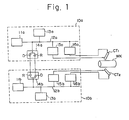
- Fig. 1 is a block diagram of the principal portions of a numerical control unit embodying the present invention, in which numerals 10a, 10b denote standard numerical control devices, 11a, 11 denote main processors, 12a, 12b denote buses, 14a, 14b denote coupling circuits, and 15a, 15b, 16a, 16b denote axis control circuits.
- WK represents a workpiece
- CT 1 , CT 2 represent cutters.
- Each coupling circuit 14a, 14b includes a driver D for transmission and a receiver R for reception, these being capable of providing an electrical connection to the buses 12a, 12b.
- the standard numerical control device 10a is capable of carrying out ordinary numerical control independently by using the arithmetic functions of its main processor 11a a to process the execution program and data stored in the main memory 13a.
- the numerical control device 10b also is capable of carrying out ordinary numerical control independently by using the arithmetic functions of its main processor 11 b to process the execution program and data stored in the main memory 13b.
- the unit of this embodiment is to be arranged as a special-purpose numerical control device for a two- headed lathe, using the two standard numerical control devices 10a, 10b of the type described.
- the buses 12a, 12b are provided with the respective coupling circuits 14a, 14b which are interconnected by cables or the like.
- the coupling circuits 14a, 14b serve as interface circuits with respect to the system of the other processor and, in the case of this embodiment, are so constructed as to be capable of directly accessing the main memories 13a, 13b in the other of the standard numerical control devices 10a, 10b by means of a program mode which uses a read/ write instruction, or a DMA (direct memory access) mode. With such an arrangement it is possible to transmit data between the two standard numerical control devices 10a, 10b. Further, the axis control circuits 15a, 16a in the standard numerical control device 10a drivably control one cutter CT 1 , and the axis control circuits 15b, 16b in the standard numerical control device 10b drivably control the other cutter CT 2 .
- one of the standard numerical control devices serves as the master, while the other standard numerical control device, namely 10b, serves as the stave.
- the standard numerical control device 10a controls the cutter CT, as well as the overall system, and the standard numerical control device 10b controls the other cutter CT 2 .
- synchronization between the two devices is established by exchanging the information required on the master and slave sides.
- the master may send the slave such information as a start command, stop command, the amount of travel, the feed speed, etc.
- the slave may send the master such information as a halt request due to an alarm, an operation completion signal, and the like.
- Such information is transmitted using the coupling circuits 14a, 14b.
- the unit of the present embodiment constitutes a single special-purpose numerical control device obtained by interconnecting two standard numerical control devices 10a, 10b in such a manner that they can exchange data with each other.
- This permits a mass-produced standard numerical control device of an ordinary construction to be utilized intact, without the provision of unique hardware and software as in a conventional special-purpose numerical control device. Consequently, a market can be supplied with an inexpensive special-purpose numerical control device in a short delivery time.
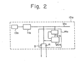
- Fig. 2 is a block diagram showing a modification of the master numerical control device 10a of Fig. 1.
- Numeral 20a denotes a special-purpose memory for data transfer, and 21a a timing control circuit.
- the device according to this embodiment is so arranged that the special-purpose memory 20a for data transfer, which memory is accessable by both the main processor 11 a of the numerical control device 10a and that of the other numerical control device (not shown), is provided within the coupling circuit 14a, and that the transmission of data between the master and slave is carried out through the special-purpose memory 20a, without there being any direct access to the main memory of the companion numerical control device. Accordingly, the access of the main processor to its main memory is not interrupted by a data transfer, so that an improvement in efficiency is achieved. Further, the other numerical control device may access the special-purpose memory 20a by adopting a program mode or DMA mode.
- the present invention may be applied to the control of machine tools that require to be controlled in a complex fashion, such as a machine tool having a large number of controlled axes, or a lathe having two heads.
Landscapes
- Engineering & Computer Science (AREA)
- General Engineering & Computer Science (AREA)
- Manufacturing & Machinery (AREA)
- Quality & Reliability (AREA)
- Physics & Mathematics (AREA)
- General Physics & Mathematics (AREA)
- Automation & Control Theory (AREA)
- Numerical Control (AREA)
- General Factory Administration (AREA)
- Control By Computers (AREA)
Claims (1)
- Numerische Steuereinheit zum Steuern einer Werkzeugmaschine, dadurch gekennzeichnet, daß mehrere numerische Standard-Steuereinheiten (10a, 10b) vorgesehen sind, wovon jede einen Prozessor (11a, 11b) enthält und in der Lage ist, Daten durch Benutzung der arithmetischen Funktionen des Prozessors (11a, 11b) zu verarbeiten, und daß jede numerische Standard-Steuereinheit (10a, 10b) mit einer Verbindungsschaltung (14a, 14b) versehen ist, die als Schnittstellenschaltung zum Austausch von Daten mit der mindestens einen anderen numerischen Standard-Steuereinheit arbeitet, wobei eine der numerischen Standard-Steuereinheiten, die als eine Haupt-Steuereinheit (10a) dient, und jede andere numerische Standard-Steuereinheit, die als eine Neben-Steuereinheit (10b) dient, durch die Verbindungsschaltungen (14a, 14b) miteinander verbunden sind, wobei eine einzige Werkzeugmaschine numerisch durch die mehreren numerischen Standard-Steuereinheiten (10a, 10b) unter Gesamtsteuerung derjenigen numerischen Standard-Steuereinheit steuerbar ist, die als die Haupt-Steuereinheit (10a) dient, und wobei die Verbindungsschaltung (14a) derjenigen numerischen Standard-Steuereinheit, die als die Haupt-Steuereinheit (10a) dient, mit einem Speicher (20a) für Sonderaufgaben für Datenübertragung ausgestattet ist, zu welchem Speicher (20a) durch die Prozessoren (11a, 11b) sowohl der Haupt-Steuereinheit (10a) als auch der mindestens einen Neben-Steuereinheit (10b) Zugriff erfolgen kann.
Applications Claiming Priority (2)
| Application Number | Priority Date | Filing Date | Title |
|---|---|---|---|
| JP92382/80 | 1980-07-07 | ||
| JP9238280A JPS5717012A (en) | 1980-07-07 | 1980-07-07 | Numerical controller |
Publications (3)
| Publication Number | Publication Date |
|---|---|
| EP0055301A1 EP0055301A1 (de) | 1982-07-07 |
| EP0055301A4 EP0055301A4 (de) | 1982-11-25 |
| EP0055301B1 true EP0055301B1 (de) | 1986-10-08 |
Family
ID=14052866
Family Applications (1)
| Application Number | Title | Priority Date | Filing Date |
|---|---|---|---|
| EP81901899A Expired EP0055301B1 (de) | 1980-07-07 | 1981-07-07 | Numerische steuereinheit |
Country Status (4)
| Country | Link |
|---|---|
| US (1) | US4587607A (de) |
| EP (1) | EP0055301B1 (de) |
| JP (1) | JPS5717012A (de) |
| WO (1) | WO1982000211A1 (de) |
Families Citing this family (14)
| Publication number | Priority date | Publication date | Assignee | Title |
|---|---|---|---|---|
| BE896745A (fr) * | 1982-05-14 | 1983-09-16 | Gnb Batteries Inc | Appareil et procede pour le soudage de connexions entre elements de batteries. |
| JPS59223807A (ja) * | 1983-06-01 | 1984-12-15 | Mitsubishi Electric Corp | 数値制御装置の結合方式 |
| JPS6219355A (ja) * | 1985-07-15 | 1987-01-28 | Yamazaki Mazak Corp | 工作機械の運転制御方法 |
| GB2188749A (en) * | 1986-01-07 | 1987-10-07 | Electric Design Limited | Programmable timer |
| JPS62236650A (ja) * | 1986-04-01 | 1987-10-16 | Fanuc Ltd | 4軸旋盤のncプログラム作成方法 |
| JPS6414616A (en) * | 1987-07-08 | 1989-01-18 | Mitsubishi Electric Corp | Numerical controller |
| JPH01282486A (ja) * | 1988-05-09 | 1989-11-14 | Omron Tateisi Electron Co | 認識システムのデータ処理方式 |
| JPH02183809A (ja) * | 1989-01-10 | 1990-07-18 | Fanuc Ltd | トランスファーライン用数値制御装置 |
| JP2840297B2 (ja) * | 1989-06-20 | 1998-12-24 | ファナック株式会社 | 数値制御装置の軸制御方法 |
| DE9406446U1 (de) * | 1993-06-25 | 1994-11-03 | Siemens Ag | Ansteuerbaustein zur Ansteuerung eines Schützes |
| JP3308386B2 (ja) * | 1994-04-25 | 2002-07-29 | ファナック株式会社 | 制御システム |
| JP2004199433A (ja) * | 2002-12-19 | 2004-07-15 | Fanuc Ltd | 同期制御装置 |
| WO2007057390A2 (en) * | 2005-11-16 | 2007-05-24 | Abb Ab | Method and device for controlling motion of an industrial robot with a position switch |
| JPWO2024261913A1 (de) * | 2023-06-21 | 2024-12-26 |
Family Cites Families (9)
| Publication number | Priority date | Publication date | Assignee | Title |
|---|---|---|---|---|
| US3626385A (en) * | 1969-12-30 | 1971-12-07 | Ibm | Time-shared numerical control system |
| FR2182357A5 (de) * | 1972-04-28 | 1973-12-07 | Gachot Jean | |
| IT1062827B (it) * | 1976-03-29 | 1985-02-11 | Olivetti Controllo Numerico | Sistema di controllo numerico per macchine utensili |
| US4058711A (en) * | 1976-04-16 | 1977-11-15 | Cincinnati Milacron Inc. | Asynchronous dual function multiprocessor machine control |
| US4149235A (en) * | 1976-12-27 | 1979-04-10 | Mcdonnell Douglas Corporation | Computer numerical control system for machine tool |
| JPS54106780A (en) * | 1978-02-08 | 1979-08-22 | Toshiba Mach Co Ltd | Controlling of plural machine tools |
| JPS54126547U (de) * | 1978-02-24 | 1979-09-04 | ||
| US4251858A (en) * | 1979-03-06 | 1981-02-17 | The Boeing Company | Paging, status monitoring and report compiling system for support, maintenance and management of operator-supervised automatic industrial machines |
| JPS55146552A (en) * | 1979-05-02 | 1980-11-14 | Hitachi Ltd | N 1 backkup method of dispersion type hierarchy system |
-
1980
- 1980-07-07 JP JP9238280A patent/JPS5717012A/ja active Pending
-
1981
- 1981-07-07 WO PCT/JP1981/000156 patent/WO1982000211A1/ja not_active Ceased
- 1981-07-07 EP EP81901899A patent/EP0055301B1/de not_active Expired
- 1981-07-07 US US06/705,055 patent/US4587607A/en not_active Expired - Lifetime
Non-Patent Citations (2)
| Title |
|---|
| ELECTRONIC DESIGN, vol. 16, no. 11, May 24, 1978, ROCHELLE PARK (US), D. MOSS: "Multiprocessing adds muscle to uPS", pages 238-243 * |
| SIEMENS POWER ENGINEERING, vol. 1, no. 11, november 1979, BERLIN (DE), K.R. HOFFMANN et al.: "Sinumerik sprint 8T, a manually programmable numerical control for lathes", pages 343-347 * |
Also Published As
| Publication number | Publication date |
|---|---|
| WO1982000211A1 (en) | 1982-01-21 |
| EP0055301A1 (de) | 1982-07-07 |
| JPS5717012A (en) | 1982-01-28 |
| EP0055301A4 (de) | 1982-11-25 |
| US4587607A (en) | 1986-05-06 |
Similar Documents
| Publication | Publication Date | Title |
|---|---|---|
| EP0055301B1 (de) | Numerische steuereinheit | |
| US5252899A (en) | Numerical control system | |
| US4628442A (en) | Centralized peripheral interface with a numerical control unit | |
| EP0707251A1 (de) | Steuersystem | |
| EP0275048B1 (de) | Direktspeicherzugriffssteuerung | |
| EP0067228A1 (de) | Digitale steuereinheit | |
| JPS59223807A (ja) | 数値制御装置の結合方式 | |
| JPS61154493A (ja) | サーボモータの駆動制御装置 | |
| JPS59218531A (ja) | 情報処理装置 | |
| EP0577431B1 (de) | Verfahren zur Rückstellung gekoppelter Module und ein dieses Verfahren verwendendes System | |
| JPS5852768A (ja) | マイクロプロセツサの構成方式 | |
| US4837684A (en) | Data input/output system for application system in numerical control equipment | |
| JP3352101B2 (ja) | シーケンスコントローラ及びインターフェース方法 | |
| JPS60263208A (ja) | フアクトリ−・オ−トメイシヨン・システム | |
| JPH04100341A (ja) | シリアルデータ通信方法 | |
| JPS6126706B2 (de) | ||
| JP3227273B2 (ja) | プログラマブルコントローラのリンク処理方式 | |
| SU1221656A1 (ru) | Многоканальное устройство управлени обменом информацией между ЭВМ | |
| EP0404939A1 (de) | Numerische steuerung | |
| JPS62290903A (ja) | 複数のプログラマブルコントロ−ラの接続方式 | |
| JPS6353607A (ja) | コンピユ−タ化数値制御装置 | |
| CA1246721A (en) | Central controlling system for n.c machines group | |
| JPH04144337A (ja) | 通信方式 | |
| JP2735112B2 (ja) | 数値制御装置のデータ・リード・ライト方式 | |
| GB2106674A (en) | Magnetic bubble memory device |
Legal Events
| Date | Code | Title | Description |
|---|---|---|---|
| PUAI | Public reference made under article 153(3) epc to a published international application that has entered the european phase |
Free format text: ORIGINAL CODE: 0009012 |
|
| 17P | Request for examination filed |
Effective date: 19820308 |
|
| AK | Designated contracting states |
Designated state(s): DE FR GB |
|
| RAP1 | Party data changed (applicant data changed or rights of an application transferred) |
Owner name: FANUC LIMITED |
|
| RAP1 | Party data changed (applicant data changed or rights of an application transferred) |
Owner name: FANUC LTD |
|
| GRAA | (expected) grant |
Free format text: ORIGINAL CODE: 0009210 |
|
| AK | Designated contracting states |
Kind code of ref document: B1 Designated state(s): DE FR GB |
|
| REF | Corresponds to: |
Ref document number: 3175441 Country of ref document: DE Date of ref document: 19861113 |
|
| ET | Fr: translation filed | ||
| PLBE | No opposition filed within time limit |
Free format text: ORIGINAL CODE: 0009261 |
|
| STAA | Information on the status of an ep patent application or granted ep patent |
Free format text: STATUS: NO OPPOSITION FILED WITHIN TIME LIMIT |
|
| 26N | No opposition filed | ||
| PGFP | Annual fee paid to national office [announced via postgrant information from national office to epo] |
Ref country code: FR Payment date: 19910620 Year of fee payment: 11 |
|
| PGFP | Annual fee paid to national office [announced via postgrant information from national office to epo] |
Ref country code: GB Payment date: 19910625 Year of fee payment: 11 |
|
| PG25 | Lapsed in a contracting state [announced via postgrant information from national office to epo] |
Ref country code: GB Effective date: 19920707 |
|
| GBPC | Gb: european patent ceased through non-payment of renewal fee |
Effective date: 19920707 |
|
| PG25 | Lapsed in a contracting state [announced via postgrant information from national office to epo] |
Ref country code: FR Effective date: 19930331 |
|
| REG | Reference to a national code |
Ref country code: FR Ref legal event code: ST |
|
| PGFP | Annual fee paid to national office [announced via postgrant information from national office to epo] |
Ref country code: DE Payment date: 19930719 Year of fee payment: 13 |
|
| PG25 | Lapsed in a contracting state [announced via postgrant information from national office to epo] |
Ref country code: DE Effective date: 19950401 |