EP0055400A2 - Dispositif d'escamotage - Google Patents
Dispositif d'escamotage Download PDFInfo
- Publication number
- EP0055400A2 EP0055400A2 EP81110194A EP81110194A EP0055400A2 EP 0055400 A2 EP0055400 A2 EP 0055400A2 EP 81110194 A EP81110194 A EP 81110194A EP 81110194 A EP81110194 A EP 81110194A EP 0055400 A2 EP0055400 A2 EP 0055400A2
- Authority
- EP
- European Patent Office
- Prior art keywords
- film
- shaft
- information
- rotation angle
- wind
- Prior art date
- Legal status (The legal status is an assumption and is not a legal conclusion. Google has not performed a legal analysis and makes no representation as to the accuracy of the status listed.)
- Granted
Links
Images


Classifications
-
- G—PHYSICS
- G03—PHOTOGRAPHY; CINEMATOGRAPHY; ANALOGOUS TECHNIQUES USING WAVES OTHER THAN OPTICAL WAVES; ELECTROGRAPHY; HOLOGRAPHY
- G03B—APPARATUS OR ARRANGEMENTS FOR TAKING PHOTOGRAPHS OR FOR PROJECTING OR VIEWING THEM; APPARATUS OR ARRANGEMENTS EMPLOYING ANALOGOUS TECHNIQUES USING WAVES OTHER THAN OPTICAL WAVES; ACCESSORIES THEREFOR
- G03B17/00—Details of cameras or camera bodies; Accessories therefor
- G03B17/36—Counting number of exposures
-
- G—PHYSICS
- G03—PHOTOGRAPHY; CINEMATOGRAPHY; ANALOGOUS TECHNIQUES USING WAVES OTHER THAN OPTICAL WAVES; ELECTROGRAPHY; HOLOGRAPHY
- G03B—APPARATUS OR ARRANGEMENTS FOR TAKING PHOTOGRAPHS OR FOR PROJECTING OR VIEWING THEM; APPARATUS OR ARRANGEMENTS EMPLOYING ANALOGOUS TECHNIQUES USING WAVES OTHER THAN OPTICAL WAVES; ACCESSORIES THEREFOR
- G03B1/00—Film strip handling
- G03B1/60—Measuring or indicating length of the used or unused film; Counting number of exposures
- G03B1/64—Measuring or indicating length of the used or unused film; Counting number of exposures by means which as certain the radius of the film coiled on a spool
-
- G—PHYSICS
- G03—PHOTOGRAPHY; CINEMATOGRAPHY; ANALOGOUS TECHNIQUES USING WAVES OTHER THAN OPTICAL WAVES; ELECTROGRAPHY; HOLOGRAPHY
- G03B—APPARATUS OR ARRANGEMENTS FOR TAKING PHOTOGRAPHS OR FOR PROJECTING OR VIEWING THEM; APPARATUS OR ARRANGEMENTS EMPLOYING ANALOGOUS TECHNIQUES USING WAVES OTHER THAN OPTICAL WAVES; ACCESSORIES THEREFOR
- G03B17/00—Details of cameras or camera bodies; Accessories therefor
- G03B17/42—Interlocking between shutter operation and advance of film or change of plate or cut-film
- G03B17/425—Interlocking between shutter operation and advance of film or change of plate or cut-film motor drive cameras
Definitions
- This invention relates to a film feeding device, more specifically to a film feeding device for feeding a film at regular pitches.
- the object of this invention is to provide a film feeding device capable of constant-pitch film feeding irrespectively of the change of film wind shaft diameter.
- a film feeding device which comprises film wind driving means engaging and rotating a film wind shaft, film wind shaft diameter detecting means for producing information representing the diameter of the film wind shaft, wound film length detecting means for detecting the length of a film wound on the film wind shaft and producing wound film length information, means for deciding the rotation angle of the film wind shaft in accordance with the shaft diameter information and the wound film length information, and means for driving the film wind driving means to rotate the film wind shaft through the angle decided by the rotation angle deciding means.
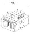
- a camera 11 which contains therein a film cassette 12.
- a mirror shutter 14 is disposed opposite to a film 13 in the film cassette 12.
- a wind shaft 15 of the film cassette 12 is coupled with a shaft 17a of a film wind motor 17 by means of a transmission gear unit 16.
- a motor 18 is provided for driving the mirror shutter 14. When the mirror shutter 14 is raised by the motor 18, the film 13 is exposed to an incident light transmitted through a camera lens system 19.
- the film wind shaft 15 of the film cassette 12 is provided with an engaging hole 15a which engages a shaft 20 coupled to the transmission gear unit 16.
- the shaft 20, which is composed of an engaging portion 20a to engage the engaging hole 15a, a step portion 20b, a shaft portion 20c, and a gear portion 20d, is attached to a baseplate 21 so as to be able to move axially.
- a spring 22 is provided for urging the shaft 20 toward the film cassette 12.
- the gear portion 20d is in mesh with a gear in the transmission gear unit 16.
- the driving source portion of the transmission gear unit 16 is coupled with the shaft 17a of the motor 17.
- a film cassette type setting switch 23 is disposed in close vicinity to the film wind shaft 15. As shown in Fig.
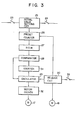
- the film cassette type setting switch 23, along with a back cover switch 24, is connected to the control input terminal of an initial value setting circuit 25.
- the output terminal of the initial value setting circuit 25 is connected with the preset terminal of a preset counter 26 whose output terminal is connected to the address port of a R OM (read-only memory) 27.
- the address of the ROM 27, storing motor drive data as shown in Table 1, is . designated by output data from the preset counter 26.
- the output terminal of the ROM 27 is connected to one comparison input terminal of a comparator 28 whose output terminal is connected to the reset terminal of an oscillator 29.
- the oscillator 29 is so designed as to be set for oscillation in response to the output of a release circuit 30.
- the output terminal of the oscillator 29 is connected to the respective input terminals of a counter 31 and a motor driver 32.
- the output terminals of the counter 31 and the motor driver 32 are connected to the other comparison input terminal of the comparator 28 and the film feeding motor 17, . respectively.
- the release circuit 30 is connected to a release switch 33 to operate in response to the operation of the switch 33.
- the camera 11 is loaded with a 20-exposure film cassette.
- the engaging hole 15a is formed deep in the film wind shaft 15 of the film cassette 12.
- the switch 23 is open in this state.
- the initial value setting circuit 25 of Fig. 3 sets the preset counter 26 for a value, e.g. "0", which represents the film wind shaft diameter of the 20-exposure film cassette.
- the release switch 33 drives a shutter mechanism section including the mirror shutter motor 18.
- the release circuit 28 supplies the oscillator 29 with a release completion signal.
- the oscillator 29 oscillates in response to the release completion signal, and supplies a pulse signal to the counter 31 and the motor driver 32.
- the motor driver 32 rotates the film feeding motor 17 in synchronism with the pulse signal.
- the rotation of the motor 17 is transmitted to the shaft 20 by the transmission gear unit 16.
- the counter 31 counts the pulses of the pulse signal, and supplies the count value to the comparator 28.
- the comparator 28 -compares the count value from the counter 31 with the data from the ROM 27.
- the preset counter 26 is set to "00", and data "100" corresponding to the address 00 of Table 1 is read out from the ROM 27 whose address is designated by the preset counter 26.
- the data "100" which corresponds to the pulse number of the pulse signal, is compared with the count data from the counter 31.
- the output signal of the comparator 28 stops the oscillator 29 from producing output pulses, thereby stopping the rotation of the pulse motor 17.
- the pulse motor 17 has made revolutions corresponding to 100 pulses to cause the wind shaft 15 to rotate through an angle corresponding to the revolutions of the motor 17 and correspondingly to wind the film thereon.
- the release circuit 28 produces a film winding completion signal to cause the preset counter 26 to count up, that is, the shaft diameter information is updated.
- the release circuit 28 produces the release completion signal again to operate the motor driver 32.
- an update address signal "01" is delivered from the preset counter 26, so that the ROM 27 produces data "98".
- the wind shaft 15 rotates through an angle corresponding to the rotation of the pulse motor 17 responsive to 98 pulses.
- the decrease of 2 pulses compared with the 100 pulses for the preceding rotation corresponds to an increase of the film wind shaft diameter caused by the film winding. Constant-pitch film feeding is achieved by thus decreasing the number of revolutions of the pulse motor 17.
- the 20-exposure film cassette is used in the above-mentioned embodiment, there will now be described a case where the camera unit is loaded with a 40-exposure film cassette.
- the film wind shaft and the engaging hole of the 40-exposure film cassette are thinner and shallower than those of the 20-exposure film cassette, respectively. Therefore, when the drive shaft 20 engages the engaging hole 115a of the film wind shaft 115 of the 40-exposure film cassette 12, the step portion 20b of the drive shaft 20 stays in an upper position. Accordingly, the step portion 20b abuts against the switch 23 to close the same.
- the initial value setting circuit 25 presets the preset counter 26 to "21".
- the pulse motor 17 is supplied with a pulse signal including 200 pulses, so that the film wind shaft 115 rotates through an angle corresponding to the rotation of the motor 17 responsive to 200 pulses, thereby winding the film thereon.
- the film in the 40-exposure film cassette is wound with a shaft rotation angle twice as wide as the rotation angle for the film in the 20-exposure film cassette, for the wind shaft of the 40-exposure film cassette is thinner than that of the 20-exposure film cassette.
- the film is wound correspondingly to the rotation of the pulse motor 17 for 197 pulses in the same manner as aforesaid. As the winding advances in this way, the film is fed at constant pitches by reducing the rotation angle of the wind shaft.
- the preset counter is used as the means for producing the addressing data of the ROM.
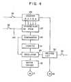
- a conventional counter 126 may be used for this purpose, as shown in Fig. 4.
- the 5-bit counter 126 is combined with a 6-bit ROM 27 so that terminals A, B, C, D and E of the counter 126 are connected to terminals A0, A1, A2, A3 and A4 of the R OM 27, respectively.
- a terminal A5 of the ROM 27 is connected to a film cassette type switch 23.
- data are stored in the ROM 27 as shown in Table 2.
- constant-pitch film feeding can accurately be performed by discriminating variations in the diameter of the wind shaft of the film cassette, setting an initial value of the rotation angle of the wind shaft on the basis of the discrimination data, and successively varying the rotation angle of the wind shaft from the initial value in accordance with the wound film length.
- the pulse motor used in the above embodiment may be replaced with a combination of a DC motor and a rotary encoder.
- the wind shaft diameter may be identified for film cassettes of various types, such as 10/20- and 20/40/60-exposure types, as well as the 20/40-exposure type.
- the film cassette type may be identified not only in response to the switching signal, but also by means of a photosensor 35 or a magnetic head 36, as shown in Fig. 5.
- an identification code is read out optically or magnetically from an identification code portion 37 or 38 attached to the film cassette 12 so that the preset counter may be preset by an identification code signal.
- the counter 31 and the comparator 28 may be replaced with a presettable subtraction counter so that the oscillator may cease to oscillate when the current number in the subtraction counter becomes "0".
Landscapes
- Physics & Mathematics (AREA)
- General Physics & Mathematics (AREA)
- Details Of Cameras Including Film Mechanisms (AREA)
Applications Claiming Priority (2)
| Application Number | Priority Date | Filing Date | Title |
|---|---|---|---|
| JP185947/80 | 1980-12-26 | ||
| JP55185947A JPS57109922A (en) | 1980-12-26 | 1980-12-26 | Film advancing device |
Publications (3)
| Publication Number | Publication Date |
|---|---|
| EP0055400A2 true EP0055400A2 (fr) | 1982-07-07 |
| EP0055400A3 EP0055400A3 (en) | 1982-10-13 |
| EP0055400B1 EP0055400B1 (fr) | 1985-01-30 |
Family
ID=16179655
Family Applications (1)
| Application Number | Title | Priority Date | Filing Date |
|---|---|---|---|
| EP81110194A Expired EP0055400B1 (fr) | 1980-12-26 | 1981-12-05 | Dispositif d'escamotage |
Country Status (4)
| Country | Link |
|---|---|
| US (1) | US4435056A (fr) |
| EP (1) | EP0055400B1 (fr) |
| JP (1) | JPS57109922A (fr) |
| DE (1) | DE3168704D1 (fr) |
Cited By (1)
| Publication number | Priority date | Publication date | Assignee | Title |
|---|---|---|---|---|
| US4918925A (en) * | 1987-09-30 | 1990-04-24 | General Electric Company | Laminar flow fuel distribution system |
Families Citing this family (4)
| Publication number | Priority date | Publication date | Assignee | Title |
|---|---|---|---|---|
| USD286408S (en) | 1984-05-28 | 1986-10-28 | Victor Hasselblad Ab | Motor drive unit for a camera |
| US7256589B2 (en) | 2001-04-27 | 2007-08-14 | Atrua Technologies, Inc. | Capacitive sensor system with improved capacitance measuring sensitivity |
| US7259573B2 (en) * | 2001-05-22 | 2007-08-21 | Atrua Technologies, Inc. | Surface capacitance sensor system using buried stimulus electrode |
| TWI241531B (en) * | 2001-05-22 | 2005-10-11 | Atrua Technologies Inc | Improved connection assembly for integrated circuit sensors |
Family Cites Families (9)
| Publication number | Priority date | Publication date | Assignee | Title |
|---|---|---|---|---|
| US3605598A (en) | 1969-03-12 | 1971-09-20 | Pentacon Dresden Veb | Photographic camera with film transport device |
| US3716299A (en) * | 1971-09-01 | 1973-02-13 | Bell & Howell Co | Frame count cuer for continuous photographic film printer |
| BE790233A (fr) * | 1971-10-18 | 1973-04-18 | Xerox Corp | Dispositif pour faire avancer une piece par bonds |
| US3774160A (en) * | 1972-02-15 | 1973-11-20 | Singer Co | Digital frame counter |
| US4021828A (en) * | 1974-02-13 | 1977-05-03 | Canon Kabushiki Kaisha | Film counter |
| DE2805515A1 (de) | 1978-02-09 | 1979-08-16 | Agfa Gevaert Ag | Vorrichtung zum einsteuern der filmempfindlichkeit durch kennungsmerkmale einer filmkassette |
| JPS6035057Y2 (ja) | 1978-09-26 | 1985-10-18 | 旭光学工業株式会社 | カ−トリッジフイルム用電動巻上カメラ |
| JPS56164331A (en) | 1980-05-23 | 1981-12-17 | Nippon Kogaku Kk <Nikon> | Motor driving device |
| JPS5766432A (en) | 1980-10-13 | 1982-04-22 | Olympus Optical Co Ltd | Automatic camera |
-
1980
- 1980-12-26 JP JP55185947A patent/JPS57109922A/ja active Pending
-
1981
- 1981-12-02 US US06/326,515 patent/US4435056A/en not_active Expired - Fee Related
- 1981-12-05 DE DE8181110194T patent/DE3168704D1/de not_active Expired
- 1981-12-05 EP EP81110194A patent/EP0055400B1/fr not_active Expired
Cited By (1)
| Publication number | Priority date | Publication date | Assignee | Title |
|---|---|---|---|---|
| US4918925A (en) * | 1987-09-30 | 1990-04-24 | General Electric Company | Laminar flow fuel distribution system |
Also Published As
| Publication number | Publication date |
|---|---|
| US4435056A (en) | 1984-03-06 |
| EP0055400B1 (fr) | 1985-01-30 |
| EP0055400A3 (en) | 1982-10-13 |
| DE3168704D1 (en) | 1985-03-14 |
| JPS57109922A (en) | 1982-07-08 |
Similar Documents
| Publication | Publication Date | Title |
|---|---|---|
| US4435056A (en) | Film feeding device | |
| US4916474A (en) | Camera having a CPU reset function | |
| JPS6323115A (ja) | カメラ | |
| JPS6197634A (ja) | カメラのための表示装置 | |
| US5471266A (en) | Data recording apparatus of camera | |
| US5862421A (en) | Light emitting element | |
| US4771309A (en) | Strobe control circuit for flash photography | |
| US4779109A (en) | Camera having film information reading device | |
| US5521661A (en) | Camera having means for indicating whether a film cartridge is loaded into or unloaded from a cartridge chamber | |
| JP3232166B2 (ja) | スプール停止位置制御装置 | |
| JP2769189B2 (ja) | 電動ズームカメラ | |
| US5768639A (en) | Diaphragm controlling device for a camera | |
| JPS60118817A (ja) | 対物レンズ選択用電動レボルバ−装置 | |
| US5907728A (en) | Photographic camera and method of and device for distinguishing condition of use of photographic film in film magazine | |
| US5734939A (en) | Camera capable of displaying information relating to the number of frames of film | |
| US6179494B1 (en) | Camera | |
| US6539178B1 (en) | Camera with system for recording photographic factor on photographed frame of photographic film | |
| EP0435281B1 (fr) | Caméra | |
| JP2855582B2 (ja) | カメラの動力伝達装置及びカメラ | |
| JPH09230415A (ja) | フィルムカートリッジの情報読取装置 | |
| JPH09318999A (ja) | カメラ | |
| JP3060057B2 (ja) | 予備巻き式カメラのdxコードの決定方法 | |
| JPH07270901A (ja) | カメラ | |
| JPH086103A (ja) | フィルム情報読取装置 | |
| JPH1152448A (ja) | カメラ及びカートリッジ情報読取り装置 |
Legal Events
| Date | Code | Title | Description |
|---|---|---|---|
| PUAI | Public reference made under article 153(3) epc to a published international application that has entered the european phase |
Free format text: ORIGINAL CODE: 0009012 |
|
| AK | Designated contracting states |
Designated state(s): AT BE CH DE FR GB IT NL SE |
|
| PUAL | Search report despatched |
Free format text: ORIGINAL CODE: 0009013 |
|
| AK | Designated contracting states |
Designated state(s): AT BE CH DE FR GB IT NL SE |
|
| RHK1 | Main classification (correction) |
Ipc: G03B 1/14 |
|
| 17P | Request for examination filed |
Effective date: 19821019 |
|
| RBV | Designated contracting states (corrected) |
Designated state(s): DE |
|
| GRAA | (expected) grant |
Free format text: ORIGINAL CODE: 0009210 |
|
| AK | Designated contracting states |
Designated state(s): DE |
|
| REF | Corresponds to: |
Ref document number: 3168704 Country of ref document: DE Date of ref document: 19850314 |
|
| PLBE | No opposition filed within time limit |
Free format text: ORIGINAL CODE: 0009261 |
|
| STAA | Information on the status of an ep patent application or granted ep patent |
Free format text: STATUS: NO OPPOSITION FILED WITHIN TIME LIMIT |
|
| 26N | No opposition filed | ||
| PGFP | Annual fee paid to national office [announced via postgrant information from national office to epo] |
Ref country code: DE Payment date: 19901119 Year of fee payment: 10 |
|
| PG25 | Lapsed in a contracting state [announced via postgrant information from national office to epo] |
Ref country code: DE Effective date: 19920901 |