EP0055539A2 - Circuit de commande pour une imprimante thermique et imprimante thermique comportant un tel circuit - Google Patents
Circuit de commande pour une imprimante thermique et imprimante thermique comportant un tel circuit Download PDFInfo
- Publication number
- EP0055539A2 EP0055539A2 EP81305790A EP81305790A EP0055539A2 EP 0055539 A2 EP0055539 A2 EP 0055539A2 EP 81305790 A EP81305790 A EP 81305790A EP 81305790 A EP81305790 A EP 81305790A EP 0055539 A2 EP0055539 A2 EP 0055539A2
- Authority
- EP
- European Patent Office
- Prior art keywords
- circuit
- voltage
- thermal printer
- heat generating
- capacitor
- Prior art date
- Legal status (The legal status is an assumption and is not a legal conclusion. Google has not performed a legal analysis and makes no representation as to the accuracy of the status listed.)
- Granted
Links
Images




Classifications
-
- B—PERFORMING OPERATIONS; TRANSPORTING
- B41—PRINTING; LINING MACHINES; TYPEWRITERS; STAMPS
- B41J—TYPEWRITERS; SELECTIVE PRINTING MECHANISMS, i.e. MECHANISMS PRINTING OTHERWISE THAN FROM A FORME; CORRECTION OF TYPOGRAPHICAL ERRORS
- B41J2/00—Typewriters or selective printing mechanisms characterised by the printing or marking process for which they are designed
- B41J2/315—Typewriters or selective printing mechanisms characterised by the printing or marking process for which they are designed characterised by selective application of heat to a heat sensitive printing or impression-transfer material
- B41J2/32—Typewriters or selective printing mechanisms characterised by the printing or marking process for which they are designed characterised by selective application of heat to a heat sensitive printing or impression-transfer material using thermal heads
- B41J2/35—Typewriters or selective printing mechanisms characterised by the printing or marking process for which they are designed characterised by selective application of heat to a heat sensitive printing or impression-transfer material using thermal heads providing current or voltage to the thermal head
- B41J2/355—Control circuits for heating-element selection
Definitions
- This invention relates to thermal printer drive circuits and to thermal printers provided therewith.
- the drive circuit has a voltage divider circuit for dividing the voltage of said power source, said voltage divider circuit comprising a first constant voltage means; a resistor and second constant voltage means connected in series, one side of said capacitor being connected to a point in said voltage divider circuit, the other side of said capacitor being arranged to be connected to one terminal of said power source.
- the drive circuit has a first voltage divider circuit composed of resistors for dividing the voltage of said power source, a second voltage divider circuit including said constant voltage means and a resistor, and a charging circuit including said capacitor one side of which is connected between a point between the first and second voltage divider circuits and the other side of which is arranged to be connected to one terminal of said power source.
- the drive circuit has a position detector for detecting a print position of said heat generating elements, said discharging circuit being arranged to be operated in synchronism with an output of said position detector.
- thermo printer having a drive circuit as recited above.
- This conventional constant temperature control circuit has a power source 1, such as a battery, whose output or supply voltage Vc varies with time, a resistor 2, and a capacitor 3.
- the capacitor 3 is connected in series with the power source 1 through the resistor 2.
- a switch 4 is connected in parallel with the capacitor 3.
- the resistor 2, the capacitor 3 and the switch 4 form a charge-discharge circuit 11.
- a switch drive circuit 5 operates (opens and closes) the switch 4 at predetermined times.
- the conventional constant temperature control circuit also has a voltage comparison circuit 6, a reference power source 7, a variable voltage divider 8, a thermal pen 9 and a switch 10 for the thermal pen.
- the switch 10 is turned on and off by the output of the voltage comparison circuit, so as to maintain the temperature of the thermal pen 9 constant irrespective of variation of the supply voltage Vc.
- the operating principle that the heat generating elements are heated to a predetermined temperature to obtain a constant print quality is equally applicable to this case.
- the capacitor 3 is discharged by momentarily closing the switch 4, a period of time t required for charging the capacitor to a voltage E, which is obtained by applying the voltage from the reference power source 7 to the variable voltage divider 8, is detected by means of the voltage comparison circuit 6, and the switch 10 is closed for a heating period t with a predetermined period T to control the temperature of the thermal pen 9.
- FIG. 2 is a diagram showing the relationship of the heating period t with the supply voltage Vc.
- the charging time is relatively short and accordingly the heating period is relatively short as indicated by t l .
- the supply voltage is relatively low as indicated by V 2
- the charging time is relatively long and accordingly the heating period is relatively long as indicated by t 2 .
- the resistance of the thermal pen 9 is represented by r
- energy per unit time P W applied to the thermal pen can be represented by the following equation:
- the heating period t can be represented by the following equation:
- Figure 3 is a logarithmic graphical representation with Vc/E as the x-axis and with t/CR as the y-axis.
- curve 31 is obtained by dividing equation 3 by CR.
- Reference numeral 32 designates a straight line having a slope of (-2).
- the locus of a point which is parallel with the straight line 32 can be represented by the following equation: where a is a constant.
- Vc is about 5.3(V). That is, equal temperature drive is effected with voltages in the range from 6.5V to 5.3V.
- a manganese dry cell SUM-3 has an internal resistance of about O.5 ⁇ . Therefore, fin the case where, as in a thermal printer, a plurality of heat generating elements each corresponding to the thermal pen 9 are supplied with current simultaneously, the supply voltage Vc falls markedly, and therefore it is necessary to use a circuit which exhibits the equal energy characteristic over a wider range of voltages. In a system in which, similarly to that of a thermal printer, energy is converted into heat instantaneously to form dots, even a small energy difference greatly affects the print quality, and accordingly a characteristic closer to the straight line 32 is required. In addition, the direction of the curve 31 is such that excessive energy is provided for both high and low voltages.
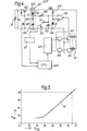
- FIG. 4 there is shown an electronic desck calculator employing one embodiment of a thermal printer drive circuit according to the present invention.
- This electronic desk calculator has a battery or power source 41, a transistor 42 which acts as a switching device for supplying current to the thermal printer drive circuit, a transistor 43 for controlling the transistor 42, the transistor 42 being maintained non-conductive (off) when the thermal printer is not operated, a first constant voltage device or Zener diode 44, a resistor 45 and a diode 46.
- the Zener diode 44, the resistor 45 and the diode 46 form a voltage divider circuit 47 for dividing a supply voltage Vc from the power source 41.
- a capacitor 50 is connected through a variable resistor 48 between the point S which is a voltage divider point of the voltage divider circuit 47 and the power source 41.
- a discharging circuit made up of a protective resistor 51 and a transistor 52 is connected in parallel with the capacitor 50.
- the voltage at the point S is indicated by Vs hereinafter.
- a voltage comparison circuit 53 acts as a switching circuit which is turned on and off according to the charge on the capacitor 50.
- a reference voltage E is developed across the Zener diode 54 connected in series with a resistor 55.
- the reference voltage E and the voltage level of the capacitor 50 are compared by the voltage comparison circuit 53, and according to the result of the comparison, the output of the voltage comparison circuit 53 is changed.
- the output of the voltage comparison circuit 53 is logic O.
- the period of time for applying current to heat generating elements 60 of the thermal printer is determined by the supply voltage.
- the elements described above form a current application time control circuit which is generaly indicated at 56 in Figure 4.
- a heat generating head 61 is made of ceramic material and incorporates the heat generating elements 60. In general, 5 x 7 matrix characters are formed with dots by moving the heat generating head 61 laterally, the heat generating elements 60 being arranged to correspond to seven dots arranged longitudinally.
- a transistor 63 which acts as a current application control device is used to control the application of current to the heat generating elements 60.
- a central processing unit (CPU) 64 is provided for processing operation and for controlling the thermal printer.
- a character signal generating circuit 65 is coupled to the CPU. In the case where a microprocessor is employed as the CPU, in general, an input/output (I/O) port is used.
- Figure 5 is a graphical representation indicating the variation of supply voltage Vc with potential Vs at the point S of the voltage divider circuit 47.
- the Zener diode 44 has a maximum Zener voltage V z of 2.5V for example.
- the diode 46 is a silicon dioxe having a maximum voltage of about 0.7V.
- the forward voltage of the diode 46 is scarcely altered even when the supply voltage Vc is decreased and the current flowing in the diode 46 is decreased. Therefore a characteristic curve 70 is obtained in Figure 5.
- the potential Vs at the point S is an actual charging potential of the capacitor 50. In the case where Vc decreases to about 4V, the potential at the point S can be approximated by the following expression:
- the output pulse width (t) of the voltage comparison circuit 53 can be represented by the following equation: where C is the capacitance of the capacitor 50, and R is the resistance of the variable registor 48. It should be noted that the output pulse width can be substantially represented by equation (6) in the case where the diode 46 is omitted. However, it is represented by the following equation in the case where the diode 46 is provided:
- curve 71 is of the current application time control circuit 56 using the voltage divider circuit 47.
- a region from point J to point K of the curve 71 corresponds to the range of x from 6.0 to 9.2 and is parallel with a straight line 72 having a slope of (-2).
- This means that the equal energy characteristic range is greatly increased when compared with that of the conventional constant temperature control circuit. In other words, even if the capacity of the power source 41 decreases and accordingly its output voltage decreases, suitable power is applied to the heat generating elements 60 and printing is produced with suitable density.
- a curve 73 indicated by a broken line in Figure 6 illustrates the case where the diode 46 is omitted.
- a region of the curve 73 which corresponds to a range of X from 6.8 to 9.2, is substantially in approximation with the straight line 72, and therefore the applicable range of voltages is wider than that of the curve 31.
- This curve 73 is sufficient for a dry cell, such as a nickelcadmium dry cell, having a relatively small range of variation of supply voltage.
- the current application time control circuit 56 may be modified in such a manner that the resistor 45 is omitted, and a series circuit of the Zener diode 44, the variable resistor 48 and the capacitor 50 is connected to the power source 41. In this modification, a curve substantially similar to the curve 73 is obtained.
- the drive circuit for the thermal printer of Figure 4 has the advantage that, as the current application time is increased with reduction in supply voltage, power is economically consumed substantially at all times.
- FIG. 7 is a circuit diagram showing an electronic desk calculator having a second embodiment of a thermal printer drive circuit according to the present invention.
- a first constant voltage device is composed of a transistor 81, a resistor 82, and a resistor 83. If the resistor 83 (or the resistor 82) is a variable resistor the potential Vz may be adjusted.
- a transistor 84 is employed as a second constant voltage device.
- a diode 85 is connected between the point S in the voltage divider circuit 47 formed of the first and second constant voltage devices, and a variable resistor 48 is connected to the capacitor 50.
- the diode 85 is used when it is required to finely change the characteristics of the circuit and therefore it may be omitted.
- reference numeral 52 designates a discharging transistor.
- the protective resistor 51 in Figure 4 is omitted from the discharging transistor 52.
- a transistor 86 is employed instead of the voltage comparison circuit 53 in Figure 4, a transistor 86 is employed.
- the transistor 86 is rendered conductive when the charge on the capacitor 50 reaches the base-emitter voltage Vbe of the transistor 86.
- a load resistor 87 is connected to the collector of the transistor 86.
- the load resistor 87 and the transistor 86 form a switching circuit.
- the variation of the output pulse width of the transistor 86 due to the variation of the base-emitter voltage Vbe attributed to temperature variation coincides with the temperature characteristic of current application time for the heat generating elements 60, thus performing temperature compensation.
- the circuit elements described so far form a current application time control circuit 90.
- the output of the current application time control circuit 90 is applied through a buffer circuit 91 to a plurality of AND gates 92.
- the heat generating elements 60 incorporated in the heat generating head 61 are divided into two groups a and b which are offset in the direction A of movement of the heat generating head 61, so that the maximum number of heat generating elements energised simultaneously is four.
- Character signal generating circuits 93, 94 are provided for the groups a and b of heat generating elements respectively.
- An electric motor 95 acts as the drive source of the thermal printer, the motor 95 being adapted to move the heat generating head 61 in the direction A or to feed a sheet of recording medium such as paper.
- a permanent magnet 96 is fixed to the shaft of the motor 95.
- the provision of the tachometer generator 98 guarantees equal dot intervals on the printing medium irrespective of the speed of the motor 95.
- the output of the tachometer generator 98 is shaped into a timing signal by a timing signal generating circuit 99, the timing signal being applied to the transistor 52 to render the latter conductive momentarily and to the CPU 64.
- the tachometer generator 98 and the timing signal generating circuit 99 form a position detector 100 which operates to detect print position.
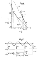
- Figure 8 is a timing diagram of the thermal printer drive circuit shown in Figure 7.
- reference numeral 101 designates the output waveform of the tachometer generator 98, the sinusoidal waveform being generated in the coil of the magnetic haed 97 as the motor is rotated
- reference numeral 102 designates the output waveform of the position detector 100, its pulse width being very small.
- the transistor 52 is rendered conductive and non-conductive repeatedly in synchronization with the period of the tachometer generator 98.
- the initial current application is at T O (a) in Figure 8, then at time T O (b) printing has been achieved for one line. Thereafter, the current application is at T1(a), T 1 (b) and so on to form a character.
- the output waveform of the transistor 96 of the current application time control circuit 56 is as indicated at 103 in Figure 8, and the pulse width varies with the supply voltage Vc.
- the pulse width (t) is iacreased to Tw 1 .
- the pulse width (t) is decreased to Tw 2 .
- the output waveform 103 and the character signal generating circuits 93, 94 are combined through the AND gates 92 to select the groups a and b of heat generating elements 60 to form desired characters.
- a temperature detecting element such as a thermistor (not shown) may be connected in series or in parallel to the variable resistor 48.
- thermal printer drive circuits shown in Figures 4 and 7 may be modified, the constant voltage devices being replaced by one or more diodes which are connected in series according to the value of the voltage Vz, with the forward characteristic of each diode being utilised.
- FIG. 9 is a perspective view of a thermal printer to which a thermal printer drive circuit according to the present invention is applied.
- An electric motor 110 is employed as the drive source.
- a reduction gear box 111 incorporates a reduction gear (not shown) which is engaged with the motor 110.
- a cam gear 112 engages with the reduction gear and operates together with a head feed cam 113.
- the head feed cam 113 has a groove 130.
- the groove 130 is engaged with a carriage 122 which supports a head 124.
- Reference numerals 114, 115 designate a clutch ratchet wheel and a clutch gear, respectively.
- a clutch spring (not shown) incorporated in the clutch ratchet wheel 114, and the clutch gear, one reciprocating rotary motion per line of printing (as indicated by the arrow B) is transmitted to a sheet feed transmission gear 116.
- a sheet feed roller 119 is mounted on the sheet feed roller shaft to feed a sheet 131 of printing medium such as paper for every line of printing.
- a platen lever 120 is engaged with a cam 121 which is integral with the sheet feed transmission gear 116.
- the platen lever 120 is urged against the carriage 122 by a platen spring 126 in the printing operation, and is released in the returning operation.
- a platen 133 is fixed to the platen lever 120.
- the carriage 122 is reciprocated along a guide shaft 123 by the head feed cam 113.
- a print head 124 having heat generating elements 125 is fixed to the carriage 123.
- a flexible power cable (FPC) 127 is connected to the head 124.
- a tachometer generator 128 is engaged with the motor 110 to detect print positions.
- a reset position detector 132 is provided to detect a printing start position of the printing head.
- a thermal printer drive circuit according to the present invention is not only applicable to the thermal printer shown in Figure 9 but also to other types of thermal printers.
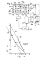
- FIG 10 is a schematic circuit diagram showing an electronic desk calculator having a third embodiment of a thermal printer drive circuit according to the present invention.
- This thermal printer drive circuit has a power source 141, for example a battery, a first voltage divider circuit 142 consisting of resistors 144, 145, ' and a second voltage divider circuit 143 including a Zener diode 146 which is a constant voltage device and a resistor 147.
- a voltage divider point 148 of the first voltage divider circuit is at a potential Vd of the power source 141 divided by a predetermined number (n).
- the second voltage divider circuit 143 utilises the characteristics of the Zener diode 146, that is at a point 149 a voltage Vd - Vz is provided (where Vz is the constant voltage of the Zener diode).
- Diodes 150, 151 are connected to the points 148, 149, respectively.
- the first voltage divider circuit 142 is coupled through the diodes 150, 151 to the second voltage divider circuit 143.
- a variable resistor 153 is connected to a common connecting point 152 of both diodes 150, 151.
- a capacitor 154 is connected between the variable resistor 153 and one terminal of the power source 141.
- the first voltage divider circuit 142, the second voltage divider circuit 143, the diodes 150, 151, the adjusting resistor 153 and the capacitor 154 form a charging circuit.
- a discharging transistor 156 is connected in parallel with the capacitor 154 to control the charge and discharge of the latter.
- a voltage comparison circuit 157 which is a type of switching circuit, is turned on and off according to the charge on the capacitor 154.
- a reference voltage E is produced by a Zener diode 158 and a series-connected resistor 159.
- the charge on the capacitor 154 is compared with the reference voltage E in the voltage comparison circuit 157, and the output level of the comparison circuit 157 is changed according to the result of the comparison. More specifically, in Figure 10, when the charge on the capacitor 154 exceeds the reference voltage E, the output of the voltage comparison circuit 157 is set to logic O.
- the elements described determine the current application time for the heat generating elements 160 of the thermal printer according to supply voltage and form a current application time control circuit.
- a heat generating head 161 made of, for example, ceramic material includes the heat generating elements 160.
- the heat generating elements 160 corresponding to 7 dots are aligned longitudinally in the heat generating head 161.
- a 5 x 7 matrix characters are formed with dots.
- a plurality of transistors 163 operate to control selectively the application of current to the heat generating elements 160.
- a central processing unit (CPU) 165 is provided to process operations and to control the thermal printer.
- a character signal generating circuit 165 is coupled to the CPU 164.
- the outputs of the character signal generating circuit 165 and the voltage comparison circuit 157 are applied to a plurality of AND gates 166, as a result of which the transistors 163 are rendered conductive for a period of time coresponding to the supply voltage Vd, and accordingly printing of desired density is produced.
- a timing signal generating circuit 187 operates to detect the position of the heat generating head 161 to generate a printing timing signal which renders the transistor 156 conductive momentarily.
- the period of time for which the transistor 156 is rendered conductive is from several to several tens of microseconds.
- Figure 11 is a graph showing the characteristics of the thermal printer drive circuit of Figure 10.
- the scale of Figure 11 is similar to that of Figure 3.
- a curve 171 is the same as the characteristic curve of the conventional constant temperature control circuit as shown in Figure 3.
- the curve 171 can be represented by the following equation: where, C is the capacitance of the capacitor 154, and R is the resistance of the variable resistor 153.
- the value t is y.C.R. and represents the period of time for which the transistor 163 is rendered conductive.
- curve 172 is obtained when only the second voltage devider circuit 143 is taken into account.
- the value t can be represented by the following equation:
- Straight lines 173, 174 in Figure 11 have a slope of (-2).
- the voltage drop across the dioders 150, 151 can be theoretically disregarded, but in practice some correction is required.
- n 0.6
- the potential at the point 148 of the first voltage divider circuit 142 is equal to the potential at the point 149 of the second voltage divider circuit 143
- n 0.6
- the supply voltage decreases below 4.OV
- a characteristic that the energy decreases with decreasing potential can be provided depending upon selection of the values Vz and n. Accordingly, the user of the electronic desk calculator can visually detect the decreased supply voltage from the reduced print density, which will prevent the calculator becoming inoperable during the printing operation.
- the thermal printer drive circuit of Figure 10 makes it possible to drive a thermal printer with a power source such as a manganese dry cell having a wide range of voltage variation and efficiently to use the capacity of the dry cell to the full.
- FIG 12 is a schematic circuit diagram of an electronic desck calculator having a fourth embodiment of a thermal printer drive circuit according to the present invention.
- the first voltage divider circuit 142 in Figure 12 is completely identical to that in Figure 10.
- the second voltage divider circuit 143 has a transistor 181 and resistors 182, 183, and utilises the constant voltage characteristics of a transistor. Therefore, if a variable resistor is employed as the resistor 183 (or the resistor 182), then the voltage Vz can be adjusted so that the characteristic can be changed.
- the switching circuit which is turned on or off according to the charge on the capacitor 154, is very simple being formed with a transistor 184 and a load resistor 185.
- a waveform shaping buffer circuit 186 is employed to apply the output of the thermal printer drive circuit to a plurality of AND gates 187.
- the reference voltage E is the base-emitter voltage (Vbe) of the transistor 184 and it is, in general,, of the order of 0.7V.
- the temperature characteristic of the base-emitter voltage coincides with the temperature characteristic of the current application time,for the heat generating elements 160, thus performing temperature compensation also. More specifically, at a low temperature the base-emitter voltage of the transistor 184 is increased and therefore the time required for charging the capacitor 154 is increased. On the other hand, when the temperature is high, the current application time is decreased. Thus, in either case, a suitable print quality can be obtained.
- the circuit elements described so far form a current application time control circuit 195.
- the heat generating elements 160 are divider into two groups a and b which are offset in the direction of movement A so that the maximum number of heat generating elements 160 energised simultaneously or the maximum number of dots printer simultaneously is four.
- Character signal generating circuits 192, 193 are provided for the groups a and b of heat generating elements, respectively.
- the thermal printer has a motor 188 as a drive source which moves the heat generating head 161 in the direction A and to operate the sheet feed unit (not shown).
- a permanent magnet 189 is fixed to the shaft of the motor 188.
- the permanent magnet 189 and a magnetic head 190 ncluding a coil form a tachometer generator 191.
- the tachometer generator 191 produces a waveform for detecting the printing timing of the groups a and b of heat generating elements 160.
- the provision of the tachometer generator 191 guarantees equal dot intervals on a sheet of printing medium (not shown) irrespective of the speed of the motor 188.
- the output of the tachometer generator 191 is converted into a waveform for rendering the transistor 156 conductive momentarily by the timing signal generating circuit, and the output of the latter is applied to the CPU 164 also.
- the tachometer generator 191 and the timing signal generating circuit 167 form a position detector 194 adapted to detect a print position.
Landscapes
- Electronic Switches (AREA)
- Facsimile Heads (AREA)
- Accessory Devices And Overall Control Thereof (AREA)
Applications Claiming Priority (2)
| Application Number | Priority Date | Filing Date | Title |
|---|---|---|---|
| JP55187626A JPS6036949B2 (ja) | 1980-12-29 | 1980-12-29 | サ−マルプリンタの駆動回路 |
| JP187626/80 | 1980-12-29 |
Publications (3)
| Publication Number | Publication Date |
|---|---|
| EP0055539A2 true EP0055539A2 (fr) | 1982-07-07 |
| EP0055539A3 EP0055539A3 (en) | 1983-07-27 |
| EP0055539B1 EP0055539B1 (fr) | 1986-07-16 |
Family
ID=16209395
Family Applications (1)
| Application Number | Title | Priority Date | Filing Date |
|---|---|---|---|
| EP81305790A Expired EP0055539B1 (fr) | 1980-12-29 | 1981-12-08 | Circuit de commande pour une imprimante thermique et imprimante thermique comportant un tel circuit |
Country Status (4)
| Country | Link |
|---|---|
| US (1) | US4409600A (fr) |
| EP (1) | EP0055539B1 (fr) |
| JP (1) | JPS6036949B2 (fr) |
| DE (1) | DE3174942D1 (fr) |
Cited By (1)
| Publication number | Priority date | Publication date | Assignee | Title |
|---|---|---|---|---|
| EP0197549A3 (en) * | 1985-04-08 | 1987-01-28 | Kabushiki Kaisha Sato | Thermal head temperature control device |
Families Citing this family (20)
| Publication number | Priority date | Publication date | Assignee | Title |
|---|---|---|---|---|
| JPS58124678A (ja) * | 1982-01-20 | 1983-07-25 | Fuji Xerox Co Ltd | サ−マルヘツド駆動方式 |
| AU567487B2 (en) * | 1982-01-25 | 1987-11-26 | Sony Corporation | Thermal printer |
| JPS58150370A (ja) * | 1982-03-02 | 1983-09-07 | Sony Corp | プリンタにおける階調信号発生回路 |
| JPS58197063A (ja) * | 1982-05-13 | 1983-11-16 | Toshiba Corp | 印字ヘッド駆動方式 |
| US4542281A (en) * | 1984-03-02 | 1985-09-17 | Combustion Engineering, Inc. | Thermal printer contrast control |
| JPS60210473A (ja) * | 1984-04-04 | 1985-10-22 | Canon Inc | サ−マルヘツド駆動装置 |
| US4714363A (en) * | 1984-05-18 | 1987-12-22 | Seiko Epson Corporation | Print control device for a dot matrix printer |
| JPS615960A (ja) * | 1984-06-20 | 1986-01-11 | Ricoh Co Ltd | 非安定化電源を用いた感熱記録方式 |
| JPS6237179A (ja) * | 1985-08-13 | 1987-02-18 | Oki Electric Ind Co Ltd | アラ−ム検出回路 |
| DE3620535A1 (de) * | 1986-06-19 | 1987-12-23 | Mannesmann Ag | Elektronische steuerschaltung, insbesondere fuer einen drucker |
| US5432533A (en) * | 1986-07-18 | 1995-07-11 | Canon Kabushiki Kaisha | Recording method with control of head energization and recording medium conveyance power consumption |
| US5191356A (en) * | 1986-07-18 | 1993-03-02 | Canon Kabushiki Kaisha | Tower conserving recording apparatus |
| US4717924A (en) * | 1986-08-18 | 1988-01-05 | Ncr Corporation | Thermal printing control system |
| JPH0611801Y2 (ja) * | 1986-12-24 | 1994-03-30 | 富士通株式会社 | サ−マルヘツド駆動装置 |
| JPH05501992A (ja) * | 1989-11-02 | 1993-04-15 | イーストマン コダック カンパニー | 少なくとも1つの再充電可能な電池から給電される記録装置の作動方法 |
| JP2993804B2 (ja) * | 1992-09-01 | 1999-12-27 | 富士写真フイルム株式会社 | サーマルヘッドの抵抗値測定方法及び装置並びにこれを備えたサーマルプリンタ |
| JP3013042B1 (ja) * | 1998-12-21 | 2000-02-28 | セイコーインスツルメンツ株式会社 | サーマルプリンタ装置 |
| US6799004B2 (en) * | 2002-09-19 | 2004-09-28 | Hewlett-Packard Development Company, L.P. | Imaging equipment acceleration apparatus and methods |
| US7197268B2 (en) * | 2005-07-01 | 2007-03-27 | Xerox Corporation | Current measurement circuit for transformer with high frequency output |
| US8157340B2 (en) * | 2006-11-21 | 2012-04-17 | Intermec Ip Corp. | Apparatus and method for thermal printers that employ a battery or other portable power source |
Family Cites Families (7)
| Publication number | Priority date | Publication date | Assignee | Title |
|---|---|---|---|---|
| US3577137A (en) * | 1968-12-31 | 1971-05-04 | Texas Instruments Inc | Temperature compensated electronic display |
| JPS511145A (en) * | 1974-06-21 | 1976-01-07 | Copal Co Ltd | Hatsushokunodono choseikanonakannetsukirokushikidentaku |
| US3934695A (en) * | 1974-09-23 | 1976-01-27 | Hewlett-Packard Company | Method and apparatus for enhancing and maintaining character quality in thermal printers |
| JPS52141526A (en) * | 1975-10-27 | 1977-11-25 | Seiko Epson Corp | Voltage and temperature compensating control of thermal printer |
| JPS536045A (en) * | 1976-07-07 | 1978-01-20 | Hitachi Ltd | Thermal recording device |
| DE2928304C2 (de) * | 1978-07-18 | 1983-01-13 | Oki Electric Industry Co., Ltd., Tokyo | Steuerschaltung zum Aufrechterhalten einer konstanten Farbintensität bei einer thermischen Aufzeichnungsvorrichtung |
| US4262188A (en) * | 1979-01-02 | 1981-04-14 | Hewlett-Packard Company | Method and apparatus for improving print quality of a thermal printer |
-
1980
- 1980-12-29 JP JP55187626A patent/JPS6036949B2/ja not_active Expired
-
1981
- 1981-12-08 EP EP81305790A patent/EP0055539B1/fr not_active Expired
- 1981-12-08 DE DE8181305790T patent/DE3174942D1/de not_active Expired
- 1981-12-28 US US06/334,757 patent/US4409600A/en not_active Expired - Lifetime
Cited By (1)
| Publication number | Priority date | Publication date | Assignee | Title |
|---|---|---|---|---|
| EP0197549A3 (en) * | 1985-04-08 | 1987-01-28 | Kabushiki Kaisha Sato | Thermal head temperature control device |
Also Published As
| Publication number | Publication date |
|---|---|
| US4409600A (en) | 1983-10-11 |
| JPS6036949B2 (ja) | 1985-08-23 |
| DE3174942D1 (en) | 1986-08-21 |
| EP0055539B1 (fr) | 1986-07-16 |
| EP0055539A3 (en) | 1983-07-27 |
| JPS57110467A (en) | 1982-07-09 |
Similar Documents
| Publication | Publication Date | Title |
|---|---|---|
| EP0055539B1 (fr) | Circuit de commande pour une imprimante thermique et imprimante thermique comportant un tel circuit | |
| US4113391A (en) | Method for controlling voltage and providing temperature compensation in a thermal printer | |
| EP0202922B1 (fr) | Système d'impression thermique | |
| EP0613782B1 (fr) | Dispositif de commande pour imprimantes thermiques | |
| JPS5928849Y2 (ja) | プリンタ | |
| CA1162228A (fr) | Circuit d'excitation a compensation pour tete d'impression par voie thermique | |
| US20050135132A1 (en) | Power supply device and printing apparatus having the same | |
| US4442342A (en) | Thermal printer with print density control | |
| KR900014137A (ko) | 휴대용 데이터 터미널의 열전사프린터 | |
| US4714363A (en) | Print control device for a dot matrix printer | |
| JP2554871B2 (ja) | サ−マルプリンタの印字制御装置 | |
| US20100320984A1 (en) | Apparatus including power supply circuit | |
| JPS6238152B2 (fr) | ||
| JPS6238149B2 (fr) | ||
| JPH0818440B2 (ja) | サーマルヘッド | |
| JPH07102709B2 (ja) | サ−マルプリンタの印字制御装置 | |
| JPS6238151B2 (fr) | ||
| KR100212322B1 (ko) | 잉크젯 프린터의 헤드 온도 조절 장치 | |
| JPH0351162Y2 (fr) | ||
| JPS5856873A (ja) | サ−マルプリンタの駆動回路 | |
| JPH02241762A (ja) | 小型サーマルプリンタ | |
| JPS61266269A (ja) | サ−マルプリンタ | |
| JPS60132773A (ja) | サ−マルプリンタの駆動回路 | |
| JPH0939237A (ja) | インクジェットヘッド駆動電源回路 | |
| JPH0790646B2 (ja) | サ−マルプリンタの印字制御装置 |
Legal Events
| Date | Code | Title | Description |
|---|---|---|---|
| PUAI | Public reference made under article 153(3) epc to a published international application that has entered the european phase |
Free format text: ORIGINAL CODE: 0009012 |
|
| AK | Designated contracting states |
Designated state(s): DE FR GB IT |
|
| 17P | Request for examination filed |
Effective date: 19821213 |
|
| RAP1 | Party data changed (applicant data changed or rights of an application transferred) |
Owner name: EPSON CORPORATION |
|
| PUAL | Search report despatched |
Free format text: ORIGINAL CODE: 0009013 |
|
| AK | Designated contracting states |
Designated state(s): DE FR GB IT |
|
| RAP1 | Party data changed (applicant data changed or rights of an application transferred) |
Owner name: SEIKO EPSON CORPORATION |
|
| GRAA | (expected) grant |
Free format text: ORIGINAL CODE: 0009210 |
|
| AK | Designated contracting states |
Kind code of ref document: B1 Designated state(s): DE FR GB IT |
|
| PG25 | Lapsed in a contracting state [announced via postgrant information from national office to epo] |
Ref country code: IT Free format text: LAPSE BECAUSE OF FAILURE TO SUBMIT A TRANSLATION OF THE DESCRIPTION OR TO PAY THE FEE WITHIN THE PRESCRIBED TIME-LIMIT;WARNING: LAPSES OF ITALIAN PATENTS WITH EFFECTIVE DATE BEFORE 2007 MAY HAVE OCCURRED AT ANY TIME BEFORE 2007. THE CORRECT EFFECTIVE DATE MAY BE DIFFERENT FROM THE ONE RECORDED. Effective date: 19860716 |
|
| ET | Fr: translation filed | ||
| REF | Corresponds to: |
Ref document number: 3174942 Country of ref document: DE Date of ref document: 19860821 |
|
| PLBE | No opposition filed within time limit |
Free format text: ORIGINAL CODE: 0009261 |
|
| STAA | Information on the status of an ep patent application or granted ep patent |
Free format text: STATUS: NO OPPOSITION FILED WITHIN TIME LIMIT |
|
| 26N | No opposition filed | ||
| PGFP | Annual fee paid to national office [announced via postgrant information from national office to epo] |
Ref country code: GB Payment date: 19971201 Year of fee payment: 17 |
|
| PGFP | Annual fee paid to national office [announced via postgrant information from national office to epo] |
Ref country code: FR Payment date: 19971209 Year of fee payment: 17 |
|
| PGFP | Annual fee paid to national office [announced via postgrant information from national office to epo] |
Ref country code: DE Payment date: 19971212 Year of fee payment: 17 |
|
| PG25 | Lapsed in a contracting state [announced via postgrant information from national office to epo] |
Ref country code: GB Free format text: LAPSE BECAUSE OF NON-PAYMENT OF DUE FEES Effective date: 19981208 |
|
| GBPC | Gb: european patent ceased through non-payment of renewal fee |
Effective date: 19981208 |
|
| PG25 | Lapsed in a contracting state [announced via postgrant information from national office to epo] |
Ref country code: FR Free format text: LAPSE BECAUSE OF NON-PAYMENT OF DUE FEES Effective date: 19990831 |
|
| REG | Reference to a national code |
Ref country code: FR Ref legal event code: ST |
|
| PG25 | Lapsed in a contracting state [announced via postgrant information from national office to epo] |
Ref country code: DE Free format text: LAPSE BECAUSE OF NON-PAYMENT OF DUE FEES Effective date: 19991001 |