EP0056063A1 - Installation pour le transport des pièces entre des postes de travail - Google Patents
Installation pour le transport des pièces entre des postes de travail Download PDFInfo
- Publication number
- EP0056063A1 EP0056063A1 EP19810100075 EP81100075A EP0056063A1 EP 0056063 A1 EP0056063 A1 EP 0056063A1 EP 19810100075 EP19810100075 EP 19810100075 EP 81100075 A EP81100075 A EP 81100075A EP 0056063 A1 EP0056063 A1 EP 0056063A1
- Authority
- EP
- European Patent Office
- Prior art keywords
- branch
- workpiece carrier
- conveyor line
- conveyor system
- main conveyor
- Prior art date
- Legal status (The legal status is an assumption and is not a legal conclusion. Google has not performed a legal analysis and makes no representation as to the accuracy of the status listed.)
- Granted
Links
- 239000000969 carrier Substances 0.000 claims abstract description 15
- 230000002441 reversible effect Effects 0.000 claims abstract description 5
- 239000003999 initiator Substances 0.000 claims description 8
- 238000006073 displacement reaction Methods 0.000 claims 1
- 238000009415 formwork Methods 0.000 claims 1
- 238000003754 machining Methods 0.000 description 10
- 230000005540 biological transmission Effects 0.000 description 1
- 230000001934 delay Effects 0.000 description 1
- 230000000694 effects Effects 0.000 description 1
- 238000003780 insertion Methods 0.000 description 1
- 230000037431 insertion Effects 0.000 description 1
- 230000000284 resting effect Effects 0.000 description 1
- 230000033764 rhythmic process Effects 0.000 description 1
- 239000000523 sample Substances 0.000 description 1
- 230000011664 signaling Effects 0.000 description 1
- 230000001960 triggered effect Effects 0.000 description 1
- 238000011144 upstream manufacturing Methods 0.000 description 1
Images


Classifications
-
- B—PERFORMING OPERATIONS; TRANSPORTING
- B23—MACHINE TOOLS; METAL-WORKING NOT OTHERWISE PROVIDED FOR
- B23Q—DETAILS, COMPONENTS, OR ACCESSORIES FOR MACHINE TOOLS, e.g. ARRANGEMENTS FOR COPYING OR CONTROLLING; MACHINE TOOLS IN GENERAL CHARACTERISED BY THE CONSTRUCTION OF PARTICULAR DETAILS OR COMPONENTS; COMBINATIONS OR ASSOCIATIONS OF METAL-WORKING MACHINES, NOT DIRECTED TO A PARTICULAR RESULT
- B23Q7/00—Arrangements for handling work specially combined with or arranged in, or specially adapted for use in connection with, machine tools, e.g. for conveying, loading, positioning, discharging, sorting
- B23Q7/14—Arrangements for handling work specially combined with or arranged in, or specially adapted for use in connection with, machine tools, e.g. for conveying, loading, positioning, discharging, sorting co-ordinated in production lines
- B23Q7/1426—Arrangements for handling work specially combined with or arranged in, or specially adapted for use in connection with, machine tools, e.g. for conveying, loading, positioning, discharging, sorting co-ordinated in production lines with work holders not rigidly fixed to the transport devices
- B23Q7/1463—Arrangements for handling work specially combined with or arranged in, or specially adapted for use in connection with, machine tools, e.g. for conveying, loading, positioning, discharging, sorting co-ordinated in production lines with work holders not rigidly fixed to the transport devices using rotary driving means
- B23Q7/1468—Arrangements for handling work specially combined with or arranged in, or specially adapted for use in connection with, machine tools, e.g. for conveying, loading, positioning, discharging, sorting co-ordinated in production lines with work holders not rigidly fixed to the transport devices using rotary driving means comprising rollers or cogwheels, or pinions or the like
-
- B—PERFORMING OPERATIONS; TRANSPORTING
- B23—MACHINE TOOLS; METAL-WORKING NOT OTHERWISE PROVIDED FOR
- B23Q—DETAILS, COMPONENTS, OR ACCESSORIES FOR MACHINE TOOLS, e.g. ARRANGEMENTS FOR COPYING OR CONTROLLING; MACHINE TOOLS IN GENERAL CHARACTERISED BY THE CONSTRUCTION OF PARTICULAR DETAILS OR COMPONENTS; COMBINATIONS OR ASSOCIATIONS OF METAL-WORKING MACHINES, NOT DIRECTED TO A PARTICULAR RESULT
- B23Q41/00—Combinations or associations of metal-working machines not directed to a particular result according to classes B21, B23, or B24
- B23Q41/02—Features relating to transfer of work between machines
Definitions
- the invention relates to a conveyor system with at least one main conveyor line, in particular from a friction roller conveyor, for transporting workpieces or workpiece carriers with workpieces on which (manual) work is to be performed in the area of workstations.
- Such conveyor systems are mainly used in the automotive industry.
- the workpieces in particular motors, gears, axes, etc., are mounted on special workpiece carriers, which in turn are transported on the conveyor system.
- the conveyor system which may be very long, is mainly formed by friction roller conveyors. These can also be designed in various ways in the invention. However, a friction roller conveyor with the characteristics of. DE - C-25 02 557. In this design principle, friction shafts with friction rollers arranged on them are driven by bevel gears through a main shaft.
- Machining work is often carried out on the workpieces during their stay on the conveyor system. Insofar as these are carried out by machines or machine tools, a momentary stopping of the workpiece carriers in the area of the machine tools installed next to a main conveyor line is required. Manual processing is often carried out during onward transport. In any case, the machining of workpieces during their stay on the main conveyor line is disadvantageous because this necessarily results in delays in the movement sequence.
- the invention has for its object to further develop and improve a conveyor system of the type mentioned in such a way that machining, in particular manual work, can be carried out on workpieces without disturbing the transport flow on the main conveyor line.
- the conveyor system according to the invention is characterized in that in the region of a work station at least one branch of a conveyor directed transversely to the main conveyor line connects to the main conveyor line, the workpiece to be machined being able to be conveyed into the branch.
- a work station to be operated by a worker is assigned two branches which are arranged on the same side of the main conveyor line and are at an appropriate distance from one another.
- This streamlines the workflow since the worker in question, after carrying out the machining on a workpiece of one branch, can turn directly to machining a workpiece in the region of the other branch by rotating through 180 °.
- Several such work stations are arranged in the area of the main conveyor line. Since the workpieces or workpiece carriers for carrying out the processing can emerge from the area of the main conveyor line, respectively. in this the transport runs unhindered. The finished workpieces are automatically returned to the main conveyor line for removal.
- the workstations or the branches which are likewise equipped with a friction roller conveyor are equipped in a special way.
- the length of these branches corresponds approximately to the length of the workpiece or the workpiece carrier plus an adequate working margin compared to the main conveyor line.
- the retracted workpiece carrier is automatically locked in the branch, so that relative movements in one direction or the other are excluded for the duration of the machining.
- the friction roller conveyor in the area of this junction is equipped with a reversing drive.
- the workpiece carrier is conveyed back into the main conveyor line by reversing the drive direction, the locking of the workpiece carrier being released beforehand by starting the return conveyor movement.
- the conveyor system according to the invention is also with provided a circulating conveyor line, which extends next to the main conveyor line.
- the task of this circulating conveyor line is to pick up workpiece carriers that have not been called up for processing in the work stations, to convey them back to the beginning of the working route and to reinsert them into the main conveyor line there. This ensures that the work of the workers is not tied to fixed working hours due to the transport rhythm. Rather, a sufficient number of workpieces or workpiece carriers in the main conveyor line are always made available for retrieval. If individual workpieces are not processed, they are returned to the workstation area via the circulating conveyor line.
- the main conveyor line is equipped in the area of the branches and the connection of the circulating conveyor line with suitable devices for deriving and resuming the workpieces or workpiece carriers, in particular with a lifting station with which the respective workpiece carrier is lifted from the friction roller conveyor of the main conveyor line and reaches the branch by cross-conveying.
- a lifting station is preferably designed with the features of DE-GM-80 11 623.
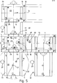
- the conveyor system shown schematically in FIG. 1 shows a section of a main conveyor line 10 with three work stations 11.
- the main conveyor line 10 is part of an extensive transport line, for example in a motor vehicle or engine factory.
- Workpieces or workpiece carriers 12 with workpieces arranged on them are transported on the main conveyor line 10, from right to left in the embodiment of FIG. 1.
- Certain (manual) tasks are to be performed on the workpieces arranged on the workpiece carriers 12.
- the main conveyor line 10 is designed as a friction roller conveyor, essentially in an embodiment according to DE-C-25 02 557.
- Friction rollers 13 arranged on the side are rotatably arranged on transverse friction shafts 14. These in turn are supported at the ends in side mounting rails 15 and 16.
- a main drive shaft 17 runs on one of these mounting rails 15, 16 and is connected to the end of a friction shaft 14 via bevel gears 18, 19.
- cross-directional branches 20, 21 are connected to the conveyor line formed in the above manner. These are used for Inclusion of one workpiece carrier 12 (or several workpiece carriers) for performing work on the workpieces.
- the length of the branch 20, 21 corresponds approximately to the length of a workpiece carrier 12 plus an adequate working latitude.
- the workpiece carrier 12 in question is stopped in the region of the branch 20, 21 on the main conveyor line 10 by a stop device 22, for. B. in the version according to DE-A-28 23 188. Then a built in this area in the main conveyor 10 lifting station 23 is actuated.
- This is preferably designed with the features of DE-GM 80 11 623.
- the workpiece carrier 12 is raised in this lifting station 13 by a lifting table with friction roller conveyor sections 24 and conveyed transversely to the main conveyor line 10.
- the friction roller conveyor section 24 is equipped in the region of the branch 20 with a separate drive (drive motor 42).
- the workpiece carrier 12 is conveyed over the side support rail 16, which is equipped for this purpose with intermediate rollers 25, into the area of one of the branches 20, 21.
- the necessary work is carried out while a workpiece carrier 12 is in the area of the branch 20, 21.
- the workpiece carrier 12 is then conveyed back into the main conveyor line 10 by a pulse triggered by the worker.
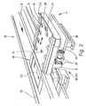
- the branch 20, 21 resting on the free end on a support frame 26 is designed as a section of a friction roller conveyor, that is to say with side mounting rails 15, 16, main drive shaft 17, bevel gears 18, 19 and friction rollers 13.
- an electric motor 27 is attached to the branch 20, 21. This. Electric motor 27 is reversible, so that the friction roller conveyor of the branch 20, 21 can convey in both directions.
- the friction rollers 13 are each in a corresponding manner Direction driven by the electric motor 27.
- the workpiece carrier 12 is releasably locked during the stay in the branch 20, 21, so that relative movements in one direction or the other are excluded.
- an automatically operating pawl 28 is attached in the region of the branch 20, 21. This is located approximately at the end of the branch 20, 21 next to its longitudinal median plane.
- the pawl 28 interacts with a stop 29 on the underside of the workpiece carrier 12.
- the pawl 28 is formed with an inclined run-up surface 30, over which the stop 29 runs when the workpiece carrier 12 is moved into the branch 20, 21 while the pawl 28 is moving downward. This then lies against the back of the stop 29 and prevents movement of the workpiece carrier 12 in the direction of the main conveyor line 10.
- a fixed stop 31 is attached to the branch 20, 21.
- the fixed stop 31 sits on a crossbar 32 between the support rails 15, 16.
- the fixed stop 31 works together with a second stop 33 on the underside of the workpiece carrier 12. The arrangement is such that the stop 29 runs past the fixed stop 31 while the stop 33 acts on it.
- the pawl 28 is designed to work automatically.
- the pawl 28 is seated at one end of a two-armed latch lever 34. This can be tilted about a transverse axis 35.
- the proportions of the pawl lever 34 are such that the pawl 28 arranged at the outer end is always loaded by its own weight into the upper locking position shown in FIG. 3.
- the pawl lever 34 is pivoted counterclockwise (with reference to FIG. 3).
- the pawl 28 is moved to return the workpiece carrier 12 after carrying out the processing in the main conveyor line 10 without any special measure by the worker, in the present case by starting up the friction rollers 13 by switching on the electric motor 27.
- the rotary movement thereby caused Friction shaft 14a results in a lowering of the pawl 38 by pivoting the pawl lever 34.
- actuating pin 36 On the friction shaft 14a there is mounted an actuating pin 36 which rotates therewith and which runs in the corresponding direction of rotation of the friction shaft 14a against the pawl lever 34 and thereby moves it counterclockwise, that is to say in the lowering sense of the pawl 28.
- the actuating pin 36 is arranged on a control roller 37 which is mounted on the friction shaft 14a with a freewheel 38.
- the freewheel 38 has the effect that the actuating pin 36 is only taken along when the friction shaft 14a rotates when the friction shaft 14a is driven in the return-conveying sense of the workpiece carrier 12. In the opposite direction of rotation, namely when the workpiece carrier 12 is fed into the branch 20, 21, the actuating pin 36 does not rotate; the latch lever 34 is therefore not operated.
- a circulation conveyor line 39 is assigned to the processing section defined by a plurality of workstations 11 in the present exemplary embodiment. This consists of a friction roller conveyor with the features already described, that is to say essentially with the structure of the main conveyor line 10.
- the circulating conveyor line 39 extends parallel to the main conveyor line 10 and is driven in the opposite direction.
- Transverse connecting sections 40 and 41 are formed at the ends of the circulating conveyor line 39 which is limited in length. These are also sections of friction roller conveyors with the features mentioned.
- workpiece carriers 12 under certain conditions, namely when machining has not been carried out, lead out of the area of the main conveyor line 10 and into the circulating conveyor line 39 or back into the main conveyor line 10, namely in a direction of conveyance past area.
- a workpiece carrier 12 which has not been called up for carrying out machining operations is thereby conveyed past the work stations 11 again.
- the connecting sections 40, 41 are arranged in the region of a work station or a branch 20/21.
- the lifting station 23 arranged here in the main conveyor line 10 for carrying out the transverse movements of the workpiece carrier 12 is designed with a drive motor 42 with a reversible direction of rotation for driving the section of the friction roller conveyor assigned to the lifting station 23.
- the workpiece carrier 12 can alternatively be fed to the branch 20, 21 and the connecting section 40 through one and the same lifting station 23.
- the lifting station 23 is designed in an analogous manner in the area of the re-introduction of the workpiece carrier 12 into the main conveyor line 10.
- the connecting sections 40, 41 convey in each case only in one transport direction, driven by the corresponding type drive motors 43. This also serves to drive a further lifting station 23 provided at the ends of the circulating conveyor line 39.
- each workpiece carrier 12 can be provided with a status code, which can be set for machining that has not yet taken place or machining of the workpiece that has already been carried out.
- This status code is read during the transport of the workpiece carrier, in such a way that the described devices of the conveyor system are actuated in one sense or another in the sense of the respective code.
- each workpiece carrier is provided on its underside with a metallic sensing element, which cooperates with initiators arranged in the region of the conveyor track.
- a metallic sensing element which cooperates with initiators arranged in the region of the conveyor track.
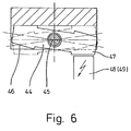
- the movable member on the workpiece carrier 12 is designed as a (metallic) rocker 44. This can be tilted about a pivot bearing 45. At the ends of the rocker 44 there are push buttons 46 and 47. The arrangement is such that, depending on the position of the rocker 44, one or the other push button 46, 47 is directed downward and thus in the position required for the transmission of a control signal is brought to a (fixed) initiator 48, 49. In Fig. 6 the probe 47 is in this relative position.
- two initiators 48 and 49 are arranged upstream of the branch 20 or the lifting station 23 belonging to it, in the direction of movement.
- one or the other initiator 48 or 49 is addressed, one reacting to the signal "finished” and the other reacting to the signal "not processed".
- the stop device 22 is actuated in such a way that the workpiece carrier in question is positioned exactly on the lifting station 23, namely stopped.
- the further sequence then follows, namely the insertion of the workpiece carrier into the branch 20.
- the lifting station 23 is acted upon by the initiator 48, 49 in such a way that the workpiece carrier continues to run on the main conveyor line 10 .
- the coding on the workpiece carrier 12, that is to say the position of the rocker 44 is changed.
- the worker actuates a pushbutton (not shown). This in turn triggers a coding magnet 53, which is arranged in the region below the rocker 44 in the branch 20. The position of the rocker 44 is changed by the coding magnet 53. If the necessary signals are now available that access to the main conveyor line 10 is free, the workpiece carrier 12 is automatically returned in the manner already described.
- an initiator 50 is provided, which has the task of sensing and signaling the status of the branch concerned. Furthermore, initiators 51 and 52 are arranged at a suitable point in the area of the lifting station 23. These have the task of triggering the necessary switching steps, if there is a workpiece carrier 12 in the exact position on the lifting station 23.
- the actuated members also include a further stop device 54, which is actuated when a workpiece carrier 12 is returned from the branch 20 into the main conveyor line 10.
Landscapes
- Engineering & Computer Science (AREA)
- Mechanical Engineering (AREA)
- Intermediate Stations On Conveyors (AREA)
- Rollers For Roller Conveyors For Transfer (AREA)
Priority Applications (2)
| Application Number | Priority Date | Filing Date | Title |
|---|---|---|---|
| DE8181100075T DE3170353D1 (en) | 1981-01-08 | 1981-01-08 | Plant for transferring workpieces subject to operating stations |
| EP19810100075 EP0056063B1 (fr) | 1981-01-08 | 1981-01-08 | Installation pour le transport des pièces entre des postes de travail |
Applications Claiming Priority (1)
| Application Number | Priority Date | Filing Date | Title |
|---|---|---|---|
| EP19810100075 EP0056063B1 (fr) | 1981-01-08 | 1981-01-08 | Installation pour le transport des pièces entre des postes de travail |
Publications (2)
| Publication Number | Publication Date |
|---|---|
| EP0056063A1 true EP0056063A1 (fr) | 1982-07-21 |
| EP0056063B1 EP0056063B1 (fr) | 1985-05-08 |
Family
ID=8187527
Family Applications (1)
| Application Number | Title | Priority Date | Filing Date |
|---|---|---|---|
| EP19810100075 Expired EP0056063B1 (fr) | 1981-01-08 | 1981-01-08 | Installation pour le transport des pièces entre des postes de travail |
Country Status (2)
| Country | Link |
|---|---|
| EP (1) | EP0056063B1 (fr) |
| DE (1) | DE3170353D1 (fr) |
Cited By (10)
| Publication number | Priority date | Publication date | Assignee | Title |
|---|---|---|---|---|
| DE3615164A1 (de) * | 1986-02-12 | 1987-08-13 | Micafil Ag | Transporteinrichtung fuer eine fertigungsstrasse mit parallelgeschalteten bearbeitungsstationen |
| FR2613969A1 (fr) * | 1987-04-16 | 1988-10-21 | Schwaebische Huettenwerke Gmbh | Dispositif de changement de palettes comportant une table de maintien |
| AT392946B (de) * | 1984-02-06 | 1991-07-10 | Sticht Walter | Verfahren und vorrichtung zum codieren von werkstuecktraegern in fertigungsanlagen |
| US5205026A (en) * | 1989-04-04 | 1993-04-27 | Walter Sticht | Production installation |
| AT406352B (de) * | 1988-03-03 | 2000-04-25 | Sticht Walter | Anlage zur bearbeitung und bzw. oder montage von bauteilen |
| EP0929483A4 (fr) * | 1996-09-25 | 2001-06-27 | Shuttleworth Inc | Appareil transporteur pour poste de travail ergonomique et procede |
| EP1125684A3 (fr) * | 2000-02-16 | 2002-12-04 | FELSOMAT GmbH & Co. KG | Système de fabrication à enchaínement et cellule d'automatisation pour celle-ci |
| EP1473112A1 (fr) * | 2003-04-28 | 2004-11-03 | GROB-Werke Burkhart Grob e.K. | Machine outil |
| EP1488884A3 (fr) * | 2003-06-06 | 2006-05-10 | GROB-Werke Burkhart Grob e.K. | Chaîne de production |
| US8096402B2 (en) * | 2009-12-30 | 2012-01-17 | Pitney Bowes Inc. | Sorter having a container shuttle system |
Families Citing this family (1)
| Publication number | Priority date | Publication date | Assignee | Title |
|---|---|---|---|---|
| DE3714108A1 (de) * | 1987-04-28 | 1988-11-17 | Manfred Von Quenaudon | Vorrichtung zur uebergabe von werkstuecktraegern |
Citations (9)
| Publication number | Priority date | Publication date | Assignee | Title |
|---|---|---|---|---|
| US2139403A (en) * | 1934-09-08 | 1938-12-06 | Gen Machinery Corp | Machine tool |
| DE1814452A1 (de) * | 1967-12-15 | 1969-08-28 | Cincinnati Milling Machine Co | Bearbeitungssystem oder Transferstrasse |
| DE2106595A1 (de) * | 1971-02-12 | 1972-10-19 | Fraunhofer Ges Forschung | Fertigungssystem, insbesondere für mittlere Stückzahlen umfassende Serienfertigung von Werkstücken |
| DE2410242A1 (de) * | 1973-06-15 | 1975-01-09 | Instandsetzungskombinat Kohle | Verfahren zum transport von werkstuecken mittels haengebahn |
| FR2306788A1 (fr) * | 1975-04-11 | 1976-11-05 | Bosch Gmbh Robert | Systeme de transport pour l'enchainement de postes de travail paralleles en une chaine de travail |
| DE2749678A1 (de) * | 1976-11-05 | 1978-05-11 | Maurice Prodel | Transfer-maschine mit mehreren arbeitsstationen und einer die arbeitsstation durchlaufenden endlosen transportvorrichtung mit einer vielzahl von werkstuecktraegern |
| FR2369906A1 (fr) * | 1976-11-05 | 1978-06-02 | Prodel Maurice | Machine-transfert a plusieurs postes pour l'assemblage et/ou l'usinage de pieces |
| EP0003024A1 (fr) * | 1978-01-11 | 1979-07-25 | Gebr. Heller Maschinenfabrik GmbH | Système de fabrication flexible |
| EP0013733A1 (fr) * | 1979-01-10 | 1980-08-06 | Robert Bosch Gmbh | Système variable de transport et d'assemblage |
-
1981
- 1981-01-08 EP EP19810100075 patent/EP0056063B1/fr not_active Expired
- 1981-01-08 DE DE8181100075T patent/DE3170353D1/de not_active Expired
Patent Citations (9)
| Publication number | Priority date | Publication date | Assignee | Title |
|---|---|---|---|---|
| US2139403A (en) * | 1934-09-08 | 1938-12-06 | Gen Machinery Corp | Machine tool |
| DE1814452A1 (de) * | 1967-12-15 | 1969-08-28 | Cincinnati Milling Machine Co | Bearbeitungssystem oder Transferstrasse |
| DE2106595A1 (de) * | 1971-02-12 | 1972-10-19 | Fraunhofer Ges Forschung | Fertigungssystem, insbesondere für mittlere Stückzahlen umfassende Serienfertigung von Werkstücken |
| DE2410242A1 (de) * | 1973-06-15 | 1975-01-09 | Instandsetzungskombinat Kohle | Verfahren zum transport von werkstuecken mittels haengebahn |
| FR2306788A1 (fr) * | 1975-04-11 | 1976-11-05 | Bosch Gmbh Robert | Systeme de transport pour l'enchainement de postes de travail paralleles en une chaine de travail |
| DE2749678A1 (de) * | 1976-11-05 | 1978-05-11 | Maurice Prodel | Transfer-maschine mit mehreren arbeitsstationen und einer die arbeitsstation durchlaufenden endlosen transportvorrichtung mit einer vielzahl von werkstuecktraegern |
| FR2369906A1 (fr) * | 1976-11-05 | 1978-06-02 | Prodel Maurice | Machine-transfert a plusieurs postes pour l'assemblage et/ou l'usinage de pieces |
| EP0003024A1 (fr) * | 1978-01-11 | 1979-07-25 | Gebr. Heller Maschinenfabrik GmbH | Système de fabrication flexible |
| EP0013733A1 (fr) * | 1979-01-10 | 1980-08-06 | Robert Bosch Gmbh | Système variable de transport et d'assemblage |
Cited By (10)
| Publication number | Priority date | Publication date | Assignee | Title |
|---|---|---|---|---|
| AT392946B (de) * | 1984-02-06 | 1991-07-10 | Sticht Walter | Verfahren und vorrichtung zum codieren von werkstuecktraegern in fertigungsanlagen |
| DE3615164A1 (de) * | 1986-02-12 | 1987-08-13 | Micafil Ag | Transporteinrichtung fuer eine fertigungsstrasse mit parallelgeschalteten bearbeitungsstationen |
| FR2613969A1 (fr) * | 1987-04-16 | 1988-10-21 | Schwaebische Huettenwerke Gmbh | Dispositif de changement de palettes comportant une table de maintien |
| AT406352B (de) * | 1988-03-03 | 2000-04-25 | Sticht Walter | Anlage zur bearbeitung und bzw. oder montage von bauteilen |
| US5205026A (en) * | 1989-04-04 | 1993-04-27 | Walter Sticht | Production installation |
| EP0929483A4 (fr) * | 1996-09-25 | 2001-06-27 | Shuttleworth Inc | Appareil transporteur pour poste de travail ergonomique et procede |
| EP1125684A3 (fr) * | 2000-02-16 | 2002-12-04 | FELSOMAT GmbH & Co. KG | Système de fabrication à enchaínement et cellule d'automatisation pour celle-ci |
| EP1473112A1 (fr) * | 2003-04-28 | 2004-11-03 | GROB-Werke Burkhart Grob e.K. | Machine outil |
| EP1488884A3 (fr) * | 2003-06-06 | 2006-05-10 | GROB-Werke Burkhart Grob e.K. | Chaîne de production |
| US8096402B2 (en) * | 2009-12-30 | 2012-01-17 | Pitney Bowes Inc. | Sorter having a container shuttle system |
Also Published As
| Publication number | Publication date |
|---|---|
| EP0056063B1 (fr) | 1985-05-08 |
| DE3170353D1 (en) | 1985-06-13 |
Similar Documents
| Publication | Publication Date | Title |
|---|---|---|
| DE2756422C2 (de) | Fertigungsanlage für in mehreren Schritten herzustellende Bauteile | |
| EP0062267B1 (fr) | Système de fabrication et d'assemblage | |
| DE3304090C2 (fr) | ||
| DE3730434C2 (fr) | ||
| DD140559A5 (de) | Fertigungsanlage fuer in zwei oder mehreren schritten herzustellende bauteile | |
| DE4409532A1 (de) | Handhabungssystem | |
| DE1814452A1 (de) | Bearbeitungssystem oder Transferstrasse | |
| DE69001317T2 (de) | Automatischer hoch- und niedergeschwindigkeits-sortierfoerderer. | |
| DE4100477A1 (de) | Vorrichtung zur behandlung von gegenstaenden | |
| DE2342445A1 (de) | Palettiervorrichtung | |
| DE2608393C2 (de) | Förderanlage | |
| DE4229067A1 (de) | Flexibles Transportsystem | |
| EP0056063A1 (fr) | Installation pour le transport des pièces entre des postes de travail | |
| DE20202491U1 (de) | Zuführvorrichtung zum Zuführen von Werkstückträgern in Längsrichtung eines Gurtförderers zu einer Bearbeitungsstation | |
| DE3422150C2 (fr) | ||
| CH690575A5 (de) | Weichenmodul zum Ein- oder Ausschleusen eines Werkstückträgers. | |
| DE69808980T2 (de) | Palettenwechsler | |
| DE3538149C2 (fr) | ||
| DE9404713U1 (de) | Handhabungssystem | |
| DE19546887A1 (de) | Förderbahn für Paletten | |
| DE3508841C2 (fr) | ||
| DE4111632C2 (de) | Montagelinie | |
| EP0252107A1 (fr) | Dispositif pour usiner des pieces en forme de plaques, ainsi que des lattes ou des poutrelles. | |
| EP0450556A2 (fr) | Appareil de transfert | |
| DE4112279C2 (de) | Vorrichtung zum Transport und zur Übergabe von Werkstückträgern in vernetzten Transfersystemen mit Linearachsen |
Legal Events
| Date | Code | Title | Description |
|---|---|---|---|
| PUAI | Public reference made under article 153(3) epc to a published international application that has entered the european phase |
Free format text: ORIGINAL CODE: 0009012 |
|
| 17P | Request for examination filed |
Effective date: 19811128 |
|
| AK | Designated contracting states |
Designated state(s): DE FR GB IT NL SE |
|
| GRAA | (expected) grant |
Free format text: ORIGINAL CODE: 0009210 |
|
| AK | Designated contracting states |
Designated state(s): DE FR GB IT NL SE |
|
| PG25 | Lapsed in a contracting state [announced via postgrant information from national office to epo] |
Ref country code: NL Effective date: 19850508 Ref country code: IT Free format text: LAPSE BECAUSE OF FAILURE TO SUBMIT A TRANSLATION OF THE DESCRIPTION OR TO PAY THE FEE WITHIN THE PRESCRIBED TIME-LIMIT;WARNING: LAPSES OF ITALIAN PATENTS WITH EFFECTIVE DATE BEFORE 2007 MAY HAVE OCCURRED AT ANY TIME BEFORE 2007. THE CORRECT EFFECTIVE DATE MAY BE DIFFERENT FROM THE ONE RECORDED. Effective date: 19850508 |
|
| PG25 | Lapsed in a contracting state [announced via postgrant information from national office to epo] |
Ref country code: SE Effective date: 19850530 |
|
| REF | Corresponds to: |
Ref document number: 3170353 Country of ref document: DE Date of ref document: 19850613 |
|
| NLV1 | Nl: lapsed or annulled due to failure to fulfill the requirements of art. 29p and 29m of the patents act | ||
| PLBE | No opposition filed within time limit |
Free format text: ORIGINAL CODE: 0009261 |
|
| STAA | Information on the status of an ep patent application or granted ep patent |
Free format text: STATUS: NO OPPOSITION FILED WITHIN TIME LIMIT |
|
| 26N | No opposition filed | ||
| REG | Reference to a national code |
Ref country code: FR Ref legal event code: CD |
|
| REG | Reference to a national code |
Ref country code: GB Ref legal event code: 732 |
|
| PGFP | Annual fee paid to national office [announced via postgrant information from national office to epo] |
Ref country code: GB Payment date: 19921229 Year of fee payment: 13 |
|
| PGFP | Annual fee paid to national office [announced via postgrant information from national office to epo] |
Ref country code: FR Payment date: 19930111 Year of fee payment: 13 |
|
| PGFP | Annual fee paid to national office [announced via postgrant information from national office to epo] |
Ref country code: DE Payment date: 19930127 Year of fee payment: 13 |
|
| PG25 | Lapsed in a contracting state [announced via postgrant information from national office to epo] |
Ref country code: GB Effective date: 19940108 |
|
| GBPC | Gb: european patent ceased through non-payment of renewal fee |
Effective date: 19940108 |
|
| PG25 | Lapsed in a contracting state [announced via postgrant information from national office to epo] |
Ref country code: FR Effective date: 19940930 |
|
| PG25 | Lapsed in a contracting state [announced via postgrant information from national office to epo] |
Ref country code: DE Effective date: 19941001 |
|
| REG | Reference to a national code |
Ref country code: FR Ref legal event code: ST |