EP0057118A2 - Elektromechanisches Druckwerk für einen Serienparalleldrucker - Google Patents
Elektromechanisches Druckwerk für einen Serienparalleldrucker Download PDFInfo
- Publication number
- EP0057118A2 EP0057118A2 EP82400032A EP82400032A EP0057118A2 EP 0057118 A2 EP0057118 A2 EP 0057118A2 EP 82400032 A EP82400032 A EP 82400032A EP 82400032 A EP82400032 A EP 82400032A EP 0057118 A2 EP0057118 A2 EP 0057118A2
- Authority
- EP
- European Patent Office
- Prior art keywords
- motor
- movement
- sheet
- print head
- rotation
- Prior art date
- Legal status (The legal status is an assumption and is not a legal conclusion. Google has not performed a legal analysis and makes no representation as to the accuracy of the status listed.)
- Granted
Links
- 238000007639 printing Methods 0.000 title claims abstract description 25
- 230000033001 locomotion Effects 0.000 claims abstract description 50
- 230000005540 biological transmission Effects 0.000 claims abstract description 26
- 230000001131 transforming effect Effects 0.000 claims abstract description 9
- 230000001360 synchronised effect Effects 0.000 claims description 7
- 238000006073 displacement reaction Methods 0.000 description 7
- 238000000034 method Methods 0.000 description 3
- 125000004122 cyclic group Chemical group 0.000 description 1
- 238000004519 manufacturing process Methods 0.000 description 1
- 230000009347 mechanical transmission Effects 0.000 description 1
- 230000033764 rhythmic process Effects 0.000 description 1
- 238000007651 thermal printing Methods 0.000 description 1
Images

Classifications
-
- B—PERFORMING OPERATIONS; TRANSPORTING
- B41—PRINTING; LINING MACHINES; TYPEWRITERS; STAMPS
- B41J—TYPEWRITERS; SELECTIVE PRINTING MECHANISMS, i.e. MECHANISMS PRINTING OTHERWISE THAN FROM A FORME; CORRECTION OF TYPOGRAPHICAL ERRORS
- B41J25/00—Actions or mechanisms not otherwise provided for
- B41J25/001—Mechanisms for bodily moving print heads or carriages parallel to the paper surface
- B41J25/006—Mechanisms for bodily moving print heads or carriages parallel to the paper surface for oscillating, e.g. page-width print heads provided with counter-balancing means or shock absorbers
-
- B—PERFORMING OPERATIONS; TRANSPORTING
- B41—PRINTING; LINING MACHINES; TYPEWRITERS; STAMPS
- B41J—TYPEWRITERS; SELECTIVE PRINTING MECHANISMS, i.e. MECHANISMS PRINTING OTHERWISE THAN FROM A FORME; CORRECTION OF TYPOGRAPHICAL ERRORS
- B41J19/00—Character- or line-spacing mechanisms
- B41J19/76—Line-spacing mechanisms
- B41J19/78—Positive-feed mechanisms
- B41J19/94—Positive-feed mechanisms automatically operated in response to carriage return
Definitions
- the present invention relates to electromechanical printing devices for printers of the series-parallel type.
- Serial-parallel type printers are well known. Their print head is driven in an alternating rectilinear movement parallel to the writing lines and comprises n elements (n positive integer) each capable of printing a series of k consecutive dots on a line (k positive integer).
- n elements n positive integer
- k positive integer k positive integer
- current printers use a rotary motor coupled to an eccentric (or to a cam) placed in a light formed in the print head.
- these printers include an auxiliary rotary motor coupled to a movement device. the printing sheet, and a motor control circuit. This circuit controls the motors in order to animate the print head in a reciprocating linear movement parallel to the writing lines and to advance the printing sheet as soon as the writing of a line is finished.
- the disadvantage of the two motors and their control circuit is that they are expensive.
- a printing device comprising a single motor, a roller supporting a sheet, a fixed printing head, first transmission elements transforming the rotary movement generated by the motor into a rotation movement of the roller around its axis, to advance the sheet, and second transmission elements transforming the rotary movement generated by the motor into a reciprocating and rectilinear movement moving the roller parallel to its axis and in synchronism with its rotational movement.
- a device is described in European patent application No. 80 400632.8, it has the disadvantage of difficult access to the sheet of paper, the print head being fixed to the frame, on the one hand, and on the other hand the roller being connected to the chassis by two mechanical transmission systems, one to ensure its alternating and rectilinear movement and the other to ensure its rotation.
- the present invention relates to an electromechanical printing device having the advantage of using only one rotary motor for control both the advance of the paper and the movement of the print head, which results in a lower production cost, and on the other hand requiring only a rotation of the roller, which simplifies the system putting it in motion so that you can easily move the roller to handle the sheet of paper.
- an electromechanical printing device for a printer of the series-parallel type, comprising: a printing head intended for printing a sheet; a rotary motor; a roller supporting the sheet; first transmission elements transforming the rotary movement generated by the motor into a rotation movement of the roller around its axis, to advance the sheet, is characterized in that it comprises second transmission elements transforming the rotary movement generated by the motor in an alternating and rectilinear movement applied to the print head, perpendicular and synchronous with the movement of advancement of the sheet.
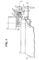
- This device comprises a rotary step-by-step motor 4, a thermal printing head 1 intended for printing a sheet of electro-sensitive paper 2, a roller 3 on which the sheet of paper 2 is placed, and transmission elements transforming the rotary movement printed by the motor 4, on the one hand in a rectilinear reciprocating movement animating the printing head 1, and on the other hand in a rotary movement animating the roller 3.
- the direction of the rectilinear reciprocating movement printed at the head d 'impression 1 is y'y. This direction is parallel to the registration lines of the sheet 2 and the axis of rotation of the roller 3.
- a rotation of the roller 3 causes a displacement of the sheet of paper in a direction perpendicular to the writing lines.
- the principle implemented by the transmission elements of the device consists in synchronizing the movements of the print head 1 and of the roller 3 in order to allow a paper advance at the end of the writing of a line and before the start. the registration of a new line.
- the displacement of the print head 1 is generated by an eccentric 5 placed inside a light formed in the print head 1.
- this eccentric 5 is coupled to the motor 4 by means of a transmission axis 6 which corresponds to the axis of rotation of the eccentric 5 and to the motor shaft 4. It follows that the eccentric 5 transforms the stepping rotation movement generated by the motor 4 into a reciprocating rectilinear movement, of direction y'y, animating the print head 1.
- the displacement of the print head 1 is carried out from a first extreme position (position 1) to a second extreme position (position 2) .
- the pitch of the motor 4 is 90 ° and the number of stops of this motor during a cycle of the translational movement of the print head 1 is four. Each engine stop corresponds to an extreme position of the print head 1.
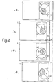
- FIGS. 2a, 2b, 2c and 2d allow a better understanding of the movement animating the print head 1.
- the print head 1 the transmission axis 6, the eccentric 5, and the rectangular section 30 of the light formed in the printing head 1, seen from the section plane AA of FIG. 1.
- an orthogonal coordinate system OX 1 y has also been shown, the origin of which O corresponds to the center of the section of the transmission axis 6. This coordinate system is only used to reveal the rotary movement of the eccentric 5.
- the instants t l , t 2 , t 3 and t 4 correspond to the four instants at which the engine 4 stops during a cycle of the translational movement of the print head 1.
- Figure 2a corresponds to the position of the print head 1 at time t l .
- This position is the first extreme position of the print head 1, it is position 1.
- the axis of transmission 6 rotates 90 ° and causes a linear displacement of the print head 1. This displacement has the amplitude d.
- the eccentric 5 and the print head 1 are in the position shown in Figure 2b.
- This position corresponds to the second extreme position of the print head 1, this is position 2.
- the transmission axis 6 again rotates 90 °, but this rotation does not cause no translation of the print head 1.
- the print head 1 is therefore always in position 2 as shown in FIG. 2c.
- the electrodes of the print head 1 are controlled to print the sheet at the characteristic instants t l , t 2 , t 3 and t 4 of each cycle of the movement of the print head 1. In fact, these instants correspond to on the one hand at the instants of stopping the printhead 1 and on the other hand at extreme positions of the printhead 1. For each writing line, it is necessary that each electrode can print two different dots.
- the method consists in giving a first print order to the n electrodes at time t l , in moving the print head 1 between the instants t 1 and t 2 , in giving a second print order to the n electrodes at at time t 2 , to command an advance of the printing sheet between times t 2 and t 3 so as to present to the n electrodes a blank writing line, and so on.
- transmission elements have been placed between the motor 4 and the roller 3 which transforms the rotary movement of the motor 4 into a rotary movement which only drives the roller 3 'between, on the one hand the instants t 2 and t 31 and on the other hand the instants t 3 and t 4 of the rotation cycle of the motor 4.
- the advance of the sheet will be controlled between the end of the inscription of each line and the start of the registration of the next line.
- the motor 4 is coupled to the roller 3 via a transmission consisting of: a first synchronous pulley 7 whose axis of rotation corresponds to l axis 6, and a second synchronous pulley 9 linked to the synchronous pulley 7 by means of the toothed belt 8, a worm 11 whose axis of rotation 10 of direction x'x corresponds to l the axis of rotation of the pulley 9, of a toothed wheel 12 meshed with the worm 11, of a toothed wheel 13 whose axis of rotation 20 corresponds to the axis of rotation of the toothed wheel 12, and of a toothed wheel 14 meshed with the toothed wheel 13 and having an axis of rotation 15 corresponding to the axis of rotation of the roller 3.
- a transmission consisting of: a first synchronous pulley 7 whose axis of rotation corresponds to l axis 6, and a second synchronous pulley 9 linked to the synchronous pulley 7 by means of the toothed belt
- the transmission consisting of pulleys 7 and 9, the transmission axis 6, the axis of rotation 10, and the toothed belt 8, serves to drive the worm 11 in a rotational movement around the axis 10.
- the multiplication ratio of this gear is 1, so that a 90 ° rotation of the motor shaft 4 corresponds to a 90 ° rotation of the screw 11.
- the gear consisting of the toothed wheels 13 and 14 and transmission axes 15 and 20 it serves to drive the roller 3 in a rotational movement around the axis 15.
- Each gear step of the tooth wheel 12 corresponds to a rotation of the roller 3 which drives an advance of sheet 2 over a length equal to the interval between two consecutive inscription lines.
- the gear relating to the toothed wheel 12 and the worm 11 is the most complex. To better understand its operation, this gear has been represented in FIG. 3, seen from the section plane BB of FIG. 1.
- the face of the tooth wheel 12 which is seen from this cutting plane BB comprises all of the teeth d. (i varying from 1 to 32). These teeth i have a cylindrical shape. They are distributed on a concentric circle at the circumference of the wheel and mesh successively in the thread of the endless screw 11.
- the shape of the thread is alternately helical and circular.
- the rhythm of the change in shape of the thread corresponds to a quadrant of the screw 11. In fact, as shown in FIG. 3, the thread of the screw 11 is circular on a quadrant of the screw, helical on the next quadrant, then circular And so on.
- the screw comprises an active part, consisting of the two quadrants comprising the thread of helical shape, and an inactive part consisting of the two quadrants comprising the thread of circular shape.
- an active part consisting of the two quadrants comprising the thread of helical shape
- an inactive part consisting of the two quadrants comprising the thread of circular shape.
- the screw 11 is previously positioned so that the active part of the screw corresponds to a pitch of rotation of the motor 4 taking place, either between the instants t 2 and t 3 , or between the instants t 4 and t l of each cycle of rotation, and that the inactive part corresponds to the pitch of rotation taking place either between the instants t 1 and t 2 , or between the instants t 3 and t 4 .
- the screw 11 generates a rotation of the toothed wheel 12 and therefore an advance of the sheet 2, only between the instants t 2 and t 3 and that between the instants t 4 and t of each rotation cycle motor 4.
- the roll 3 can easily be moved away from the print head 1.
- the toothed wheels 13 and 14 constitute a convenient means for transmitting a rotational movement to the roller 3 while allowing it to be moved away from the print head 1.
Landscapes
- Character Spaces And Line Spaces In Printers (AREA)
- Impact Printers (AREA)
- Common Mechanisms (AREA)
Applications Claiming Priority (2)
| Application Number | Priority Date | Filing Date | Title |
|---|---|---|---|
| FR8101464A FR2498524B1 (fr) | 1981-01-27 | 1981-01-27 | Dispositif electromecanique d'impression pour imprimante du type serie-parallele et telecopieur comportant un tel dispositif |
| FR8101464 | 1981-01-27 |
Publications (3)
| Publication Number | Publication Date |
|---|---|
| EP0057118A2 true EP0057118A2 (de) | 1982-08-04 |
| EP0057118A3 EP0057118A3 (en) | 1982-08-18 |
| EP0057118B1 EP0057118B1 (de) | 1985-01-23 |
Family
ID=9254546
Family Applications (1)
| Application Number | Title | Priority Date | Filing Date |
|---|---|---|---|
| EP82400032A Expired EP0057118B1 (de) | 1981-01-27 | 1982-01-08 | Elektromechanisches Druckwerk für einen Serienparalleldrucker |
Country Status (5)
| Country | Link |
|---|---|
| US (1) | US4420763A (de) |
| EP (1) | EP0057118B1 (de) |
| JP (1) | JPS57144781A (de) |
| DE (1) | DE3261980D1 (de) |
| FR (1) | FR2498524B1 (de) |
Cited By (7)
| Publication number | Priority date | Publication date | Assignee | Title |
|---|---|---|---|---|
| GB2140746A (en) * | 1983-05-31 | 1984-12-05 | Alps Electric Co Ltd | Thermal printer |
| EP0143522A1 (de) * | 1983-09-29 | 1985-06-05 | Ing. C. Olivetti & C., S.p.A. | Zeilenschaltmechanismus für Druckmaschine |
| EP0158017A3 (de) * | 1984-01-31 | 1986-01-29 | Nec Home Electronics Ltd. | Punktzeilendrucker |
| EP0387698A3 (de) * | 1989-03-13 | 1991-07-10 | LEPTONS ITALIA S.p.A. | Thermischer Drucker, insbesondere für Etiketten |
| EP0650845A3 (de) * | 1993-10-29 | 1997-02-19 | Hewlett Packard Co | Druckmedienzufuhr und Wagenantrieb für Schwingrahmendrucker. |
| AP619A (en) * | 1994-08-24 | 1997-10-10 | Hyal Pharma Corp | Use of hyaluronic acid or salt for the treatment of a human having a stroke or myocardial infarction. |
| CN1065819C (zh) * | 1995-02-03 | 2001-05-16 | 阿尔卑斯电气株式会社 | 热敏印字机 |
Families Citing this family (4)
| Publication number | Priority date | Publication date | Assignee | Title |
|---|---|---|---|---|
| US4520371A (en) * | 1982-12-30 | 1985-05-28 | International Business Machines Corporation | Multi-zone thermal print head |
| JPS6015170A (ja) * | 1983-07-08 | 1985-01-25 | Hitachi Koki Co Ltd | ドットラインプリンタのシャトル機構 |
| US5106216A (en) * | 1989-11-22 | 1992-04-21 | Samsung Electronics Co., Ltd. | Device for driving a platen and carriage of a printing machine |
| JP3334185B2 (ja) * | 1991-10-14 | 2002-10-15 | セイコーエプソン株式会社 | プリンタ |
Family Cites Families (7)
| Publication number | Priority date | Publication date | Assignee | Title |
|---|---|---|---|---|
| IT1000641B (it) * | 1973-12-28 | 1976-04-10 | Olivetti & Co Spa | Unita di stampa elettrotermica di tipo perfezionato |
| FR2300678A1 (fr) * | 1975-02-13 | 1976-09-10 | Logabax | Dispositif d'impression pour imprimantes rapides |
| JPS5829761B2 (ja) * | 1975-08-13 | 1983-06-24 | 住友化学工業株式会社 | 含水殺虫組成物 |
| CA1122477A (en) * | 1978-02-27 | 1982-04-27 | Akira Katsura | Printer |
| IT1108649B (it) * | 1978-04-14 | 1985-12-09 | Olivetti C Ing E C Spa | Dispositivo di stampa a punti |
| GB2046177B (en) * | 1979-03-26 | 1983-04-20 | Seiko Instr & Electronics | Printer |
| FR2457772A1 (fr) * | 1979-05-31 | 1980-12-26 | Enertec | Dispositif d'impression a deplacement transversal relatif d'une tete d'impression et d'un support d'impression applique sur un rouleau |
-
1981
- 1981-01-27 FR FR8101464A patent/FR2498524B1/fr not_active Expired
-
1982
- 1982-01-08 DE DE8282400032T patent/DE3261980D1/de not_active Expired
- 1982-01-08 EP EP82400032A patent/EP0057118B1/de not_active Expired
- 1982-01-18 US US06/340,018 patent/US4420763A/en not_active Expired - Fee Related
- 1982-01-25 JP JP57009033A patent/JPS57144781A/ja active Pending
Cited By (7)
| Publication number | Priority date | Publication date | Assignee | Title |
|---|---|---|---|---|
| GB2140746A (en) * | 1983-05-31 | 1984-12-05 | Alps Electric Co Ltd | Thermal printer |
| EP0143522A1 (de) * | 1983-09-29 | 1985-06-05 | Ing. C. Olivetti & C., S.p.A. | Zeilenschaltmechanismus für Druckmaschine |
| EP0158017A3 (de) * | 1984-01-31 | 1986-01-29 | Nec Home Electronics Ltd. | Punktzeilendrucker |
| EP0387698A3 (de) * | 1989-03-13 | 1991-07-10 | LEPTONS ITALIA S.p.A. | Thermischer Drucker, insbesondere für Etiketten |
| EP0650845A3 (de) * | 1993-10-29 | 1997-02-19 | Hewlett Packard Co | Druckmedienzufuhr und Wagenantrieb für Schwingrahmendrucker. |
| AP619A (en) * | 1994-08-24 | 1997-10-10 | Hyal Pharma Corp | Use of hyaluronic acid or salt for the treatment of a human having a stroke or myocardial infarction. |
| CN1065819C (zh) * | 1995-02-03 | 2001-05-16 | 阿尔卑斯电气株式会社 | 热敏印字机 |
Also Published As
| Publication number | Publication date |
|---|---|
| FR2498524A1 (fr) | 1982-07-30 |
| US4420763A (en) | 1983-12-13 |
| EP0057118B1 (de) | 1985-01-23 |
| DE3261980D1 (en) | 1985-03-07 |
| FR2498524B1 (fr) | 1986-07-25 |
| JPS57144781A (en) | 1982-09-07 |
| EP0057118A3 (en) | 1982-08-18 |
Similar Documents
| Publication | Publication Date | Title |
|---|---|---|
| EP0057118B1 (de) | Elektromechanisches Druckwerk für einen Serienparalleldrucker | |
| EP2356052B1 (de) | Einspeisevorrichtung einer verarbeitungseinheit mit endlosbandauflage für eine versorgungsstation in einer maschine zur herstellung von verpackungen | |
| FR2636149A1 (fr) | Dispositif de transmission a mouvement de rotation intermittent pour un mecanisme de telecommande d'appareillage electrique | |
| FR2472973A1 (fr) | Machine a ecrire electronique | |
| EP4031828B1 (de) | Zielabschussvorrichtung | |
| JP3151328B2 (ja) | インクジェットプリンタの回復装置 | |
| EP0283339A1 (de) | Grafische Vorrichtung mit Annahmeeinheit für einen ununterbrochenen Träger | |
| EP0020212B1 (de) | Druckeinrichtung mit einem Mechanismus zur relativen Querbewegung eines auf einer Druckwalze abgeordneten Aufzeichnungsträger in Bezug auf einen Druckkopf | |
| EP1494872B1 (de) | Papiereinzugsgerät für punktdrucker, z.b. tintenstrahlfotographiedrucker | |
| EP0912265B1 (de) | Vorrichtung zum regeln der grösse eines werkzeugmaschinen-blechhalters | |
| FR2601744A1 (fr) | Mecanisme d'engrenage intermittent | |
| FR2486611A1 (fr) | Systeme de transformation de mouvement circulaire continu en mouvement alternatif lineaire | |
| EP0112759A1 (de) | Mechanische Multiplexvorrichtung für einen Thermodrucker | |
| CN1161963C (zh) | 传真装置的纸张驱动控制装置 | |
| EP0439400B2 (de) | Bürogerät mit zwei Dokumentverarbeitungseinrichtungen | |
| EP0604317A1 (de) | Vorrichtung zum Einstellen der Typenräder einer Frankiermaschine | |
| EP1742802B1 (de) | Cd-druckvorrichtung | |
| FR2847512A1 (fr) | Entrainement d'un cylindre d'une machine d'impression rotative | |
| EP0023452A1 (de) | Druck-Vorrichtungen mit pulverisierter magnetischer Druckerschwärze | |
| EP1251010A1 (de) | Büromachine mit Drucker und Abtaster und multifunktionellem Motor | |
| JPH07128934A (ja) | 歯車機構およびこの歯車機構を備える原稿読み取り装置 | |
| KR100475655B1 (ko) | 팩시밀리의 원모터 구동장치 | |
| JPS5943766A (ja) | 記録紙搬送装置 | |
| EP0085007A1 (de) | Numerisch gesteuerte Maschine zum Schneiden von Glasplatten | |
| JP2005313424A (ja) | 熱転写プリンタ |
Legal Events
| Date | Code | Title | Description |
|---|---|---|---|
| PUAI | Public reference made under article 153(3) epc to a published international application that has entered the european phase |
Free format text: ORIGINAL CODE: 0009012 |
|
| PUAL | Search report despatched |
Free format text: ORIGINAL CODE: 0009013 |
|
| AK | Designated contracting states |
Designated state(s): DE GB NL |
|
| AK | Designated contracting states |
Designated state(s): DE GB NL |
|
| 17P | Request for examination filed |
Effective date: 19830114 |
|
| GRAA | (expected) grant |
Free format text: ORIGINAL CODE: 0009210 |
|
| AK | Designated contracting states |
Designated state(s): DE GB NL |
|
| REF | Corresponds to: |
Ref document number: 3261980 Country of ref document: DE Date of ref document: 19850307 |
|
| PLBE | No opposition filed within time limit |
Free format text: ORIGINAL CODE: 0009261 |
|
| STAA | Information on the status of an ep patent application or granted ep patent |
Free format text: STATUS: NO OPPOSITION FILED WITHIN TIME LIMIT |
|
| 26N | No opposition filed | ||
| PGFP | Annual fee paid to national office [announced via postgrant information from national office to epo] |
Ref country code: NL Payment date: 19890131 Year of fee payment: 10 |
|
| PGFP | Annual fee paid to national office [announced via postgrant information from national office to epo] |
Ref country code: GB Payment date: 19891231 Year of fee payment: 9 |
|
| PGFP | Annual fee paid to national office [announced via postgrant information from national office to epo] |
Ref country code: DE Payment date: 19900222 Year of fee payment: 9 |
|
| PG25 | Lapsed in a contracting state [announced via postgrant information from national office to epo] |
Ref country code: GB Effective date: 19910108 |
|
| PG25 | Lapsed in a contracting state [announced via postgrant information from national office to epo] |
Ref country code: NL Effective date: 19910801 |
|
| GBPC | Gb: european patent ceased through non-payment of renewal fee | ||
| NLV4 | Nl: lapsed or anulled due to non-payment of the annual fee | ||
| PG25 | Lapsed in a contracting state [announced via postgrant information from national office to epo] |
Ref country code: DE Effective date: 19911001 |