EP0057342A2 - Brûleur à évaporation de mazout - Google Patents
Brûleur à évaporation de mazout Download PDFInfo
- Publication number
- EP0057342A2 EP0057342A2 EP81730117A EP81730117A EP0057342A2 EP 0057342 A2 EP0057342 A2 EP 0057342A2 EP 81730117 A EP81730117 A EP 81730117A EP 81730117 A EP81730117 A EP 81730117A EP 0057342 A2 EP0057342 A2 EP 0057342A2
- Authority
- EP
- European Patent Office
- Prior art keywords
- evaporation
- pot
- oil
- combustion chamber
- annular space
- Prior art date
- Legal status (The legal status is an assumption and is not a legal conclusion. Google has not performed a legal analysis and makes no representation as to the accuracy of the status listed.)
- Granted
Links
Images


Classifications
-
- F—MECHANICAL ENGINEERING; LIGHTING; HEATING; WEAPONS; BLASTING
- F23—COMBUSTION APPARATUS; COMBUSTION PROCESSES
- F23D—BURNERS
- F23D11/00—Burners using a direct spraying action of liquid droplets or vaporised liquid into the combustion space
- F23D11/005—Burners using a direct spraying action of liquid droplets or vaporised liquid into the combustion space with combinations of different spraying or vaporising means
- F23D11/008—Burners using a direct spraying action of liquid droplets or vaporised liquid into the combustion space with combinations of different spraying or vaporising means combination of means covered by sub-groups F23D5/00 and F23D11/00
-
- F—MECHANICAL ENGINEERING; LIGHTING; HEATING; WEAPONS; BLASTING
- F23—COMBUSTION APPARATUS; COMBUSTION PROCESSES
- F23D—BURNERS
- F23D11/00—Burners using a direct spraying action of liquid droplets or vaporised liquid into the combustion space
- F23D11/04—Burners using a direct spraying action of liquid droplets or vaporised liquid into the combustion space the spraying action being obtained by centrifugal action
- F23D11/08—Burners using a direct spraying action of liquid droplets or vaporised liquid into the combustion space the spraying action being obtained by centrifugal action using a vertical shaft
Definitions
- the present invention relates to an oil vapor burner according to the preamble of the main claim.
- an oil evaporation burner in particular for burners of low power, has become known, which consists of * an outer housing in which an inner pot-like insert is rigidly fastened, the opening of which faces a combustion site. Inside this insert there is a combustion air guide insert and a conical evaporation pot which can be rotated by means of a shaft and whose opening faces away from the combustion chamber, an oil supply line opening approximately in the middle of the height of the evaporation pot. Furthermore, a fresh air blower is provided in the air supply line, evaporation pot and blower wheels are driven by the same motor.
- the oil evaporating in the pot emerges from the pot against the direction of flow and, due to the circulating exhaust gas between the duct guide element and the outer jacket of the evaporation pot, enters the combustion chamber, the fresh air supply takes place between the housing and the outer jacket of the fixed pot insert.
- a disadvantage of this embodiment is that the entire outer surface area of the evaporation pot cannot be used for the evaporation, since due to the centrifugal effect the Ü1 has a considerable thickness in its layer at the point closest to the combustion chamber. Furthermore, the evaporation can only take place indirectly via the outer wall due to the radiant and convective heat of the combustion chamber or the recirculating combustion products. There is no direct influence on the O1 in the pot. There is also the possibility that the oil vapor comes into contact with cold housing parts, so that there is condensation of already evaporated oil.
- the object of the present invention is to improve the evaporation pot and its arrangement in the oil evaporation burner decisively in order to obtain more favorable evaporation conditions, wherein at the same time this evaporation should only take place by means of recirculating combustion products in order to avoid pre-oxidation of the oil.
- this evaporation should only take place by means of recirculating combustion products in order to avoid pre-oxidation of the oil.
- It is important to ensure that thermal insulation from cold housing parts or from the fresh air is brought about in order to avoid condensation of the evaporated oil.
- the oil gasification burner according to FIG. 1 has a housing 1 which is approximately circular in cross section. In an area of larger diameter 2, the housing surrounds a combustion chamber 3. On the side facing away from the combustion chamber 3, an air supply line 4 opens, in which a fan 6 driven by a motor 5 is arranged. The fan 6 and a distributor housing 7, into which a heating oil supply line 8 opens, are penetrated by the drive shaft 9, which projects beyond the motor 5 on both sides. Behind the distributor housing 7, the shaft 9 continues as a hollow shaft, where it serves as a continuation of the oil line 8.
- the shaft 9 is guided by means of a bearing 10 in an interior 11 of an insert 12, which is cup-shaped and has an outer cylinder jacket 13 and one for this purpose has a coaxial inner cylinder jacket 14 which is approximately half the height of the outer cylinder jacket 13.
- the insert 12 is fixed and is connected to the housing 1 via a plurality of supports 15 distributed over its circumference. This creates an outer annular space 16 which is connected to the air supply line 4 and continues in an inner annular space 17, since the outer jacket 18 of the housing 1 extends around the end 19 of the outer cylinder 13 continues inside the combustion chamber 3 and here forms an inner casing shell 20 which ends in a rounding 21, which in turn is directed inwards.
- An annular opening 22 thus arises between the rounding 21 and the inner jacket 14, through which the combustion air enters the combustion chamber 3.
- a double-walled evaporation pot 23 is arranged inside the inner jacket 14 and is connected to the hollow shaft 9.
- the evaporation pot consists of an outer wall 24 and an inner wall 25, both of which are connected to one another at their end facing away from the oil supply shaft 9 via swirl vanes 39, which thus face the combustion chamber 3.
- Both walls 24 and 26 have a cylindrical shape.
- the outer wall 24 merges into a base part 27, to which the shaft 9 is connected centrally.
- a bottom 28 of the inner wall 25 is provided with a central recess 29 which is connected to the combustion chamber 3 for the purpose of recirculating the combustion products.
- the evaporation pot 23 converts the combustion chamber 3, which is in itself cylindrical, into an annular space 30, which extends approximately to the rounding 21, and into a central space 31 divided, which extends approximately to the bottom 28.
- the function of the oil evaporation burner described with reference to FIG. 1 is as follows: When the engine 5 starts up, combustion air is conveyed via the air supply line 4 into the outer annular space 16 and into the inner annular space 17, which it leaves through the annular space 22 in order to enter the annular space 30 of the Combustion chamber 3 to enter. Oil is made available to the burner via line 8 via a pump, not shown. In the area of the distributor housing 7, the oil reaches the interior of the hollow shaft 9 and is thus supplied via the bottom 27 to the inside of the outer wall of the evaporation pot 23.
- the space between the inner jacket 14 and the outer jacket 24 of the evaporation pot 23 provides thermal insulation of the evaporation pot, so that its cooling by fresh combustion air is prevented. Due to the reflection of the flame, the inner jacket 20 of the housing 1 is heated, which on the one hand leads to heating of the freshly supplied combustion air, so that condensation of already evaporated oil in the area of the inner jacket 20 is avoided.
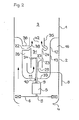
- the housing and the shape of the evaporation pot have been simplified without abandoning the basic principles of the invention:
- the housing is designed as a simple cylinder jacket which is simple in its area surrounding the combustion chamber 3.
- the end facing away from the combustion chamber in turn represents the air supply line 4 via a constriction, the air supply line 4 is assigned the fan 6 driven by a motor via a shaft 9.
- the interior of the blower 1 is formed by an insert 12 which is fixedly connected to the housing and has a bottom 33 and a cylinder jacket 13 which is connected to the inner jacket of the housing 1 over its entire circumference. So that becomes led combustion air from the fan 6 pressed into the annular space 16 between the housing 1 and the cylinder jacket 13.
- the shaft 9 - which is not designed as a hollow shaft in this exemplary embodiment - is guided over the bearing 10 and holds the hollow-cylindrical evaporation pot 23, which is single-walled here, via three webs 34 arranged in a star shape. At its lower end, it has the cylindrical recess 29 in its base 26, so that the central space 31 in the interior of the evaporation pot is connected to the annular space 26 via the recess 29.
- a cylindrical guide surface 35 is provided in the direction of the combustion chamber 3, which is connected to the jacket 13 via three cylindrical hollow supports 36.
- the annular space 16 for the combustion air is connected to the central space 31 downstream of the evaporation pot 23.
- the oil evaporates under the heat of the flame in the combustion chamber 3 on the inside of the cylindrical evaporation pot and leaves the pot via the end of the pot on the combustion chamber side.
- hot combustion gas is sucked into the annular space 26 from the combustion space 3, enters the space 11 and via the recess 29 into the interior 31 of the evaporation pot 23.
- the outside of the evaporation plug is also immediately coated by the recirculating combustion gases, so that the evaporation pot is heated from the inside and outside. Due to the cylinder 35, evaporated fuel cannot condense on cold housing parts of the evaporative burner.
- the end of the evaporation pot 23 facing away from the combustion chamber 3 can be provided with fan blades 40 instead of a bottom 28, which suck combustion products recirculating in the direction of an arrow 41 through the recess 29, so that again the interior 31 of the evaporation pot 23 is subjected to combustion products.
Landscapes
- Engineering & Computer Science (AREA)
- Chemical & Material Sciences (AREA)
- Combustion & Propulsion (AREA)
- Mechanical Engineering (AREA)
- General Engineering & Computer Science (AREA)
- Evaporation-Type Combustion Burners (AREA)
- Fats And Perfumes (AREA)
Priority Applications (1)
| Application Number | Priority Date | Filing Date | Title |
|---|---|---|---|
| AT81730117T ATE11074T1 (de) | 1981-01-31 | 1981-10-31 | Oelverdampfungsbrenner. |
Applications Claiming Priority (2)
| Application Number | Priority Date | Filing Date | Title |
|---|---|---|---|
| DE8102806 | 1981-01-31 | ||
| DE8102806U | 1981-01-31 |
Publications (3)
| Publication Number | Publication Date |
|---|---|
| EP0057342A2 true EP0057342A2 (fr) | 1982-08-11 |
| EP0057342A3 EP0057342A3 (en) | 1983-02-09 |
| EP0057342B1 EP0057342B1 (fr) | 1985-01-02 |
Family
ID=6724283
Family Applications (1)
| Application Number | Title | Priority Date | Filing Date |
|---|---|---|---|
| EP81730117A Expired EP0057342B1 (fr) | 1981-01-31 | 1981-10-31 | Brûleur à évaporation de mazout |
Country Status (3)
| Country | Link |
|---|---|
| EP (1) | EP0057342B1 (fr) |
| AT (1) | ATE11074T1 (fr) |
| DE (1) | DE3168087D1 (fr) |
Cited By (2)
| Publication number | Priority date | Publication date | Assignee | Title |
|---|---|---|---|---|
| EP0189515A3 (fr) * | 1984-12-01 | 1987-01-28 | Deutsche Babcock Werke Aktiengesellschaft | Brûleur de faible puissance et procédé pour la combustion de combustibles liquides |
| FR2665942A1 (fr) * | 1990-08-14 | 1992-02-21 | Samsung Electronics Co Ltd | Appareil de chauffage rotatif a convexion forcee. |
Family Cites Families (6)
| Publication number | Priority date | Publication date | Assignee | Title |
|---|---|---|---|---|
| GB191412821A (en) * | 1914-05-25 | 1915-02-11 | Julius Henry Becker | Improvements in Centrifugal Burners for Oil and other Liquid Fuels. |
| GB156614A (en) * | 1918-04-25 | 1922-06-06 | Ballard Oil Burning Equipment | Improved rotary oil burner |
| DE630027C (de) * | 1932-08-27 | 1936-05-19 | Junkers & Co | OElbrenner mit einem durch einen Elektromotor angetriebenen, um eine senkrechte Achse umlaufenden schalenfoermigen Zerstaeuber |
| US2559792A (en) * | 1947-08-13 | 1951-07-10 | Pietri Francois | Rotary atomizing liquid fuel burner |
| GB751218A (en) * | 1954-05-07 | 1956-06-27 | Otto Zuellig Schmid | Improvements in or relating to oil burners |
| DE2649669C2 (de) * | 1976-10-29 | 1984-06-07 | Messerschmitt-Bölkow-Blohm GmbH, 8000 München | Brenner für flüssige Brennstoffe, insbesondere Öle |
-
1981
- 1981-10-31 EP EP81730117A patent/EP0057342B1/fr not_active Expired
- 1981-10-31 AT AT81730117T patent/ATE11074T1/de not_active IP Right Cessation
- 1981-10-31 DE DE8181730117T patent/DE3168087D1/de not_active Expired
Cited By (2)
| Publication number | Priority date | Publication date | Assignee | Title |
|---|---|---|---|---|
| EP0189515A3 (fr) * | 1984-12-01 | 1987-01-28 | Deutsche Babcock Werke Aktiengesellschaft | Brûleur de faible puissance et procédé pour la combustion de combustibles liquides |
| FR2665942A1 (fr) * | 1990-08-14 | 1992-02-21 | Samsung Electronics Co Ltd | Appareil de chauffage rotatif a convexion forcee. |
Also Published As
| Publication number | Publication date |
|---|---|
| EP0057342A3 (en) | 1983-02-09 |
| ATE11074T1 (de) | 1985-01-15 |
| EP0057342B1 (fr) | 1985-01-02 |
| DE3168087D1 (en) | 1985-02-14 |
Similar Documents
| Publication | Publication Date | Title |
|---|---|---|
| DE69214154T2 (de) | Emissionsarme brennerdüse für gasturbinenanlage | |
| DE2013249C3 (de) | Ringbrennkammer für Gasturbinentriebwerke | |
| EP1110033B1 (fr) | Bruleur destine a des combustibles liquides | |
| DE19507556A1 (de) | Brenner für ein Fahrzeugheizgerät oder einen Partikelfilter-Regenerator | |
| DE2140354C3 (de) | Brenner für flüssige Brennstoffe | |
| DE2444188A1 (de) | Brennkammeranordnung mit einem drehbaren topffoermigen brennstoffverteiler | |
| EP0057342B1 (fr) | Brûleur à évaporation de mazout | |
| DE3103682A1 (de) | Oelverdampfungsbrenner | |
| DE3743205C2 (fr) | ||
| DE2706892C2 (de) | Vergaser für eine Brennkraftmaschine | |
| DE2649669C2 (de) | Brenner für flüssige Brennstoffe, insbesondere Öle | |
| DE4126745A1 (de) | Drehheizvorrichtung | |
| DE3228446C2 (fr) | ||
| DE3338543C2 (de) | Verdampfungsbrenner für flüssigen Brennstoff | |
| DE4330082C2 (de) | Brenner zur stöchiometrischen Verbrennung von flüssigem oder gasförmigem Brennstoff | |
| CH272065A (de) | Verbrennungseinrichtung. | |
| DE2843908A1 (de) | Oelzerstaeubungsbrenner, insbesondere fuer geraete kleiner leistung, z.b. fuer heizzwecke im haushalt | |
| DE2142018B2 (de) | Durchlauferhitzer mit einem heizschacht | |
| DE2715161C3 (de) | Gasturbinenanlage | |
| DE2133134A1 (de) | Vergaser fuer brennkraftmaschinen | |
| EP1915571A1 (fr) | Dispositif de combustion | |
| DE3031255C2 (de) | Glüheinsatz für einen Gebläsebrenner | |
| JPS605209Y2 (ja) | 燃焼装置 | |
| EP0151214A2 (fr) | Brûleur pour combustibles liquides du type à vaporisation | |
| DE1501842C3 (de) | Brenner fur flussige Brennstoffe |
Legal Events
| Date | Code | Title | Description |
|---|---|---|---|
| PUAI | Public reference made under article 153(3) epc to a published international application that has entered the european phase |
Free format text: ORIGINAL CODE: 0009012 |
|
| AK | Designated contracting states |
Designated state(s): AT BE CH DE FR GB IT LI LU NL SE |
|
| PUAL | Search report despatched |
Free format text: ORIGINAL CODE: 0009013 |
|
| AK | Designated contracting states |
Designated state(s): AT BE CH DE FR GB IT LI LU NL SE |
|
| RHK1 | Main classification (correction) |
Ipc: F23D 5/02 |
|
| 17P | Request for examination filed |
Effective date: 19821227 |
|
| ITF | It: translation for a ep patent filed | ||
| RAP1 | Party data changed (applicant data changed or rights of an application transferred) |
Owner name: VAILLANT GMBH Owner name: SCHONEWELLE B.V. Owner name: VAILLANT LTD. Owner name: VAILLANT GES.M.B.H Owner name: VAILLANT S.A.R.L Owner name: JOH. VAILLANT GMBH U. CO |
|
| RAP1 | Party data changed (applicant data changed or rights of an application transferred) |
Owner name: VAILLANT GMBH Owner name: SCHONEWELLE B.V. Owner name: VAILLANT LTD. Owner name: VAILLANT GES.M.B.H Owner name: VAILLANT S.A.R.L Owner name: COFRABEL N.V. Owner name: JOH. VAILLANT GMBH U. CO |
|
| GRAA | (expected) grant |
Free format text: ORIGINAL CODE: 0009210 |
|
| AK | Designated contracting states |
Designated state(s): AT BE CH DE FR GB IT LI LU NL SE |
|
| REF | Corresponds to: |
Ref document number: 11074 Country of ref document: AT Date of ref document: 19850115 Kind code of ref document: T |
|
| REF | Corresponds to: |
Ref document number: 3168087 Country of ref document: DE Date of ref document: 19850214 |
|
| ET | Fr: translation filed | ||
| PG25 | Lapsed in a contracting state [announced via postgrant information from national office to epo] |
Ref country code: LU Free format text: LAPSE BECAUSE OF NON-PAYMENT OF DUE FEES Effective date: 19851031 |
|
| PGFP | Annual fee paid to national office [announced via postgrant information from national office to epo] |
Ref country code: NL Payment date: 19851031 Year of fee payment: 5 |
|
| PLBE | No opposition filed within time limit |
Free format text: ORIGINAL CODE: 0009261 |
|
| STAA | Information on the status of an ep patent application or granted ep patent |
Free format text: STATUS: NO OPPOSITION FILED WITHIN TIME LIMIT |
|
| PGFP | Annual fee paid to national office [announced via postgrant information from national office to epo] |
Ref country code: AT Payment date: 19851108 Year of fee payment: 5 |
|
| 26N | No opposition filed | ||
| PG25 | Lapsed in a contracting state [announced via postgrant information from national office to epo] |
Ref country code: FR Free format text: LAPSE BECAUSE OF NON-PAYMENT OF DUE FEES Effective date: 19860630 |
|
| PG25 | Lapsed in a contracting state [announced via postgrant information from national office to epo] |
Ref country code: DE Effective date: 19860701 |
|
| REG | Reference to a national code |
Ref country code: FR Ref legal event code: ST |
|
| PG25 | Lapsed in a contracting state [announced via postgrant information from national office to epo] |
Ref country code: LI Effective date: 19861031 Ref country code: CH Effective date: 19861031 Ref country code: BE Effective date: 19861031 Ref country code: AT Effective date: 19861031 |
|
| PG25 | Lapsed in a contracting state [announced via postgrant information from national office to epo] |
Ref country code: SE Effective date: 19861101 |
|
| BERE | Be: lapsed |
Owner name: COFRABEL N.V. Effective date: 19861031 |
|
| PG25 | Lapsed in a contracting state [announced via postgrant information from national office to epo] |
Ref country code: NL Effective date: 19870501 |
|
| NLV4 | Nl: lapsed or anulled due to non-payment of the annual fee | ||
| REG | Reference to a national code |
Ref country code: CH Ref legal event code: PL |
|
| GBPC | Gb: european patent ceased through non-payment of renewal fee | ||
| PG25 | Lapsed in a contracting state [announced via postgrant information from national office to epo] |
Ref country code: GB Effective date: 19881121 |
|
| EUG | Se: european patent has lapsed |
Ref document number: 81730117.9 Effective date: 19870901 |