EP0058220B1 - Ferrure d'assemblage - Google Patents
Ferrure d'assemblage Download PDFInfo
- Publication number
- EP0058220B1 EP0058220B1 EP81103813A EP81103813A EP0058220B1 EP 0058220 B1 EP0058220 B1 EP 0058220B1 EP 81103813 A EP81103813 A EP 81103813A EP 81103813 A EP81103813 A EP 81103813A EP 0058220 B1 EP0058220 B1 EP 0058220B1
- Authority
- EP
- European Patent Office
- Prior art keywords
- latching
- lever
- fixture
- parts
- side face
- Prior art date
- Legal status (The legal status is an assumption and is not a legal conclusion. Google has not performed a legal analysis and makes no representation as to the accuracy of the status listed.)
- Expired
Links
- 230000037431 insertion Effects 0.000 claims description 5
- 238000003780 insertion Methods 0.000 claims description 5
- 230000000881 depressing effect Effects 0.000 claims description 2
- 230000007423 decrease Effects 0.000 claims 1
- 230000000694 effects Effects 0.000 description 3
- 238000004873 anchoring Methods 0.000 description 1
- 230000006835 compression Effects 0.000 description 1
- 238000007906 compression Methods 0.000 description 1
- 230000001419 dependent effect Effects 0.000 description 1
Images



Classifications
-
- A—HUMAN NECESSITIES
- A47—FURNITURE; DOMESTIC ARTICLES OR APPLIANCES; COFFEE MILLS; SPICE MILLS; SUCTION CLEANERS IN GENERAL
- A47B—TABLES; DESKS; OFFICE FURNITURE; CABINETS; DRAWERS; GENERAL DETAILS OF FURNITURE
- A47B47/00—Cabinets, racks or shelf units, characterised by features related to dismountability or building-up from elements
-
- F—MECHANICAL ENGINEERING; LIGHTING; HEATING; WEAPONS; BLASTING
- F16—ENGINEERING ELEMENTS AND UNITS; GENERAL MEASURES FOR PRODUCING AND MAINTAINING EFFECTIVE FUNCTIONING OF MACHINES OR INSTALLATIONS; THERMAL INSULATION IN GENERAL
- F16B—DEVICES FOR FASTENING OR SECURING CONSTRUCTIONAL ELEMENTS OR MACHINE PARTS TOGETHER, e.g. NAILS, BOLTS, CIRCLIPS, CLAMPS, CLIPS OR WEDGES; JOINTS OR JOINTING
- F16B12/00—Jointing of furniture or the like, e.g. hidden from exterior
- F16B12/10—Jointing of furniture or the like, e.g. hidden from exterior using pegs, bolts, tenons, clamps, clips, or the like
- F16B12/12—Jointing of furniture or the like, e.g. hidden from exterior using pegs, bolts, tenons, clamps, clips, or the like for non-metal furniture parts, e.g. made of wood, of plastics
- F16B12/26—Jointing of furniture or the like, e.g. hidden from exterior using pegs, bolts, tenons, clamps, clips, or the like for non-metal furniture parts, e.g. made of wood, of plastics using snap-action elements
-
- A—HUMAN NECESSITIES
- A47—FURNITURE; DOMESTIC ARTICLES OR APPLIANCES; COFFEE MILLS; SPICE MILLS; SUCTION CLEANERS IN GENERAL
- A47B—TABLES; DESKS; OFFICE FURNITURE; CABINETS; DRAWERS; GENERAL DETAILS OF FURNITURE
- A47B2230/00—Furniture jointing; Furniture with such jointing
- A47B2230/02—Assembly systems with separate fixing devices on each corner wall and a common corner joining element
-
- E—FIXED CONSTRUCTIONS
- E05—LOCKS; KEYS; WINDOW OR DOOR FITTINGS; SAFES
- E05D—HINGES OR SUSPENSION DEVICES FOR DOORS, WINDOWS OR WINGS
- E05D5/00—Construction of single parts, e.g. the parts for attachment
- E05D5/02—Parts for attachment, e.g. flaps
- E05D5/08—Parts for attachment, e.g. flaps of cylindrical shape
-
- E—FIXED CONSTRUCTIONS
- E05—LOCKS; KEYS; WINDOW OR DOOR FITTINGS; SAFES
- E05Y—INDEXING SCHEME ASSOCIATED WITH SUBCLASSES E05D AND E05F, RELATING TO CONSTRUCTION ELEMENTS, ELECTRIC CONTROL, POWER SUPPLY, POWER SIGNAL OR TRANSMISSION, USER INTERFACES, MOUNTING OR COUPLING, DETAILS, ACCESSORIES, AUXILIARY OPERATIONS NOT OTHERWISE PROVIDED FOR, APPLICATION THEREOF
- E05Y2900/00—Application of doors, windows, wings or fittings thereof
- E05Y2900/20—Application of doors, windows, wings or fittings thereof for furniture, e.g. cabinets
-
- Y—GENERAL TAGGING OF NEW TECHNOLOGICAL DEVELOPMENTS; GENERAL TAGGING OF CROSS-SECTIONAL TECHNOLOGIES SPANNING OVER SEVERAL SECTIONS OF THE IPC; TECHNICAL SUBJECTS COVERED BY FORMER USPC CROSS-REFERENCE ART COLLECTIONS [XRACs] AND DIGESTS
- Y10—TECHNICAL SUBJECTS COVERED BY FORMER USPC
- Y10S—TECHNICAL SUBJECTS COVERED BY FORMER USPC CROSS-REFERENCE ART COLLECTIONS [XRACs] AND DIGESTS
- Y10S403/00—Joints and connections
- Y10S403/11—Furniture type having a snap fit
-
- Y—GENERAL TAGGING OF NEW TECHNOLOGICAL DEVELOPMENTS; GENERAL TAGGING OF CROSS-SECTIONAL TECHNOLOGIES SPANNING OVER SEVERAL SECTIONS OF THE IPC; TECHNICAL SUBJECTS COVERED BY FORMER USPC CROSS-REFERENCE ART COLLECTIONS [XRACs] AND DIGESTS
- Y10—TECHNICAL SUBJECTS COVERED BY FORMER USPC
- Y10T—TECHNICAL SUBJECTS COVERED BY FORMER US CLASSIFICATION
- Y10T403/00—Joints and connections
- Y10T403/46—Rod end to transverse side of member
- Y10T403/4602—Corner joint
-
- Y—GENERAL TAGGING OF NEW TECHNOLOGICAL DEVELOPMENTS; GENERAL TAGGING OF CROSS-SECTIONAL TECHNOLOGIES SPANNING OVER SEVERAL SECTIONS OF THE IPC; TECHNICAL SUBJECTS COVERED BY FORMER USPC CROSS-REFERENCE ART COLLECTIONS [XRACs] AND DIGESTS
- Y10—TECHNICAL SUBJECTS COVERED BY FORMER USPC
- Y10T—TECHNICAL SUBJECTS COVERED BY FORMER US CLASSIFICATION
- Y10T403/00—Joints and connections
- Y10T403/60—Biased catch or latch
- Y10T403/608—Pivoted
Definitions
- the invention relates to a connecting fitting for releasably connecting two, preferably right-angled, plate-shaped furniture parts according to the preamble of patent claim 1.
- connection fitting of this type known from DE-U-70 47 932
- the hook-shaped projection engages with play a recess in the other fitting part, which is noticeable in an annoying wobble of the connected furniture parts relative to one another.
- this known connection fitting can only be released by depressing a pushbutton, so that difficulties can arise during disassembly if several connection fittings have to be released at the same time.
- the object of the invention is therefore to provide an easy-to-use connection fitting according to the preamble of claim 1, which enables a play-free connection of the furniture parts.
- connection fitting according to the invention is easy and convenient to use. To make the connections, the fitting parts only need to be pushed together until the locking projection engages behind the corresponding support edge of the other fitting part. When the connection fittings are released, the locking levers are held in their unlocked position by these unlocking devices, so that the connection fittings can be released before the furniture parts are taken apart, without complicated manipulations being necessary to keep them in their released position.
- a connecting fitting known from US-A-41 86 976 also has two fitting parts which can be fastened to the furniture parts to be connected, one of which is provided with a latching lever which is pivotably mounted against the force of a spring and has a front hook-shaped latching projection which is snapped in by snapping the rear flank of the Snap projection behind a support edge of the other fitting part can be connected to this.
- the rear flank of the locking projection is provided with grooves or grooves in this connection fitting, so that a self-tightening effect of the fitting parts cannot be achieved, because the rear flank cannot slide on the support edge of the other fitting part, but on this, like a ratchet, only a tooth to advance to tooth.
- the cup-shaped fitting part 46 inserted into a milled blind hole in the vertical furniture wall is provided with a slot-shaped insertion opening 47 for the latching lever 49 carrying a hook or latching projection 48.
- the underside of the insertion opening 47 rises in a wedge shape up to the bolt 45 which forms a latching edge and which is fastened in the side walls of the pot-shaped housing part 46. Behind the bolt 45, the underside of the insertion opening 47 drops steeply, forming a step.
- the bolt 45 is arranged in the rear edge of the step and thereby forms a locking edge.
- the underside of the insertion opening 47 connects approximately tangentially to the jacket of the bolt 45, while this protrudes over the falling side of the step.
- the locking lever 49 is pivotally mounted in the pot-shaped housing part 50 about the hinge pin 51 and is acted upon by the helical compression spring 52 in the direction of its locking position.
- the pin-shaped screw 54 is screwed into a threaded bore 53, which, by screwing in deeper, presses the locking lever 49 out of its locked position and fixes it in this position.
- This position of the locking lever 49 is shown in Fig. 3 in solid lines.
- the rear flank 55 of the hook 48 of the locking lever 49 is supported on the bolt 45 in the manner shown in FIG. 3 in weak solid lines.
- the flank 55 engages with a flat wedge angle on the bolt 45, so that the fitting parts shown in FIG. 3 in their locked position are clamped together.
- the bolt 45 is provided in the manner shown in FIG. 2 with grooves running in the axial direction.
- the housing part 50 is provided on both sides of the locking lever 49 with conical pins 56, 57 which engage in corresponding recesses in the housing part 46.
- the flange 58 of the housing part 46 forms in its central region a horizontal step 59 on which the housing part 50 provided with the locking lever 49 is supported with its front edge in the locked state.
- the housing part 46 is provided on its side opposite the flange 58 with short flange-like extensions 60, which are supported on the edge of the blind hole. To accommodate these extensions 60, the housing part 50 is provided with a corresponding step-shaped recess 61.
- the housing part 50 is also provided on its front with lateral hook-like projections 62, 63, which serve for better anchoring on the furniture part.
- the housing part 46 is provided with corresponding recesses for receiving the projections 62, 63.
- the fitting part provided with the locking lever is provided with a two-armed lever 64 in the embodiment shown in FIG. 4.
- this is provided with stub axles 65 in the manner shown in FIG. 5.
- the lever 64 is provided with a crank 66, so that it is fixed in its position shown in FIG. 4 in weak lines, which releases the locking.
- the longer arm 67 of the lever 65 lies in the locked position in a groove-shaped depression of the top of the housing part 50.
- the fitting part provided with the locking lever 49 consists of two parts in the manner shown in FIGS. 6 and 7 50, 50 '.
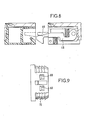
- the basic structure of the fitting part shown in FIG. 8 corresponds to that shown in FIG. 1. It differs from this essentially only in that the interlocking fitting parts are attached to the narrow ends of furniture boards and are used to connect these butt-jointed boards.
- the pins 68 arranged on the side of the latching lever 49 are longer and, as follows from the receptacles 69 of the housing part 70 that can be seen in FIG. 9, have a truncated pyramid shape.
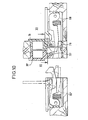
- FIGS. 10 and 11 correspond to the embodiments according to FIGS. 1 and 4 and have been modified in such a way that they allow the connection of intermediate floors or the like to a vertical furniture wall on both sides.
- the housings 78, 78 'of the fitting parts provided with the locking bolts 79, 79', which are inserted into a through hole in the vertical furniture wall, are open at the bottom in order to enable the hook parts of the locking lever to pass freely.
- the housings 78, 78 ' are identical and have laterally offset, stepped and protruding parts which engage in one another in the mirror-image assembly shown in FIG. 11.
- the locking levers of the fitting parts 80, 80 ' are arranged off-center, so that in the locked position shown in FIG. 11 they overlap one another.
Landscapes
- Engineering & Computer Science (AREA)
- General Engineering & Computer Science (AREA)
- Mechanical Engineering (AREA)
- Furniture Connections (AREA)
- Connection Of Plates (AREA)
- Hinges (AREA)
Claims (10)
Priority Applications (17)
| Application Number | Priority Date | Filing Date | Title |
|---|---|---|---|
| AT81103813T ATE15254T1 (de) | 1980-12-17 | 1981-05-18 | Verbindungsbeschlag. |
| IL64398A IL64398A0 (en) | 1980-12-17 | 1981-11-27 | Furniture connecting fitting |
| SU813364221A SU1269748A3 (ru) | 1980-12-17 | 1981-12-11 | Соединительна фурнитура |
| PT74131A PT74131B (de) | 1980-12-17 | 1981-12-15 | Verbindungsbeschlag |
| SE8107508A SE8107508L (sv) | 1980-12-17 | 1981-12-15 | Forbindningsbeslag |
| AR287836A AR229257A1 (es) | 1980-12-17 | 1981-12-16 | Herraje de union tensada y separable para dos elementos |
| AU78569/81A AU7856981A (en) | 1980-12-17 | 1981-12-16 | Furniture connection |
| HU813800A HU183747B (en) | 1980-12-17 | 1981-12-16 | Jointing armature |
| DD81235828A DD201821A5 (de) | 1980-12-17 | 1981-12-16 | Verbindungsbeschlag |
| ES1981270031U ES270031Y (es) | 1980-12-17 | 1981-12-16 | Herraje de union. |
| DK558581A DK558581A (da) | 1980-12-17 | 1981-12-16 | Forbindelsesbeslag |
| FI814041A FI814041A7 (fi) | 1980-12-17 | 1981-12-16 | Liitosheloitus. |
| BR8108180A BR8108180A (pt) | 1980-12-17 | 1981-12-16 | Guarnicao de uniao |
| NO814292A NO814292L (no) | 1980-12-17 | 1981-12-16 | Forbindelsesbeslag |
| PL1981234267A PL130085B1 (en) | 1980-12-17 | 1981-12-16 | Ferrule for disconnectably jointing two panel-like furniture components |
| CA000392576A CA1168690A (fr) | 1980-12-17 | 1981-12-17 | Raccord d'assemblage |
| RO106032A RO85241B (ro) | 1980-12-17 | 1981-12-17 | ELEMENTE DE îMBINARE PENTRU MOBILA |
Applications Claiming Priority (2)
| Application Number | Priority Date | Filing Date | Title |
|---|---|---|---|
| DE3047642 | 1980-12-17 | ||
| DE19803047642 DE3047642A1 (de) | 1980-12-17 | 1980-12-17 | Verbindungsbeschlag |
Publications (2)
| Publication Number | Publication Date |
|---|---|
| EP0058220A1 EP0058220A1 (fr) | 1982-08-25 |
| EP0058220B1 true EP0058220B1 (fr) | 1985-08-28 |
Family
ID=6119430
Family Applications (1)
| Application Number | Title | Priority Date | Filing Date |
|---|---|---|---|
| EP81103813A Expired EP0058220B1 (fr) | 1980-12-17 | 1981-05-18 | Ferrure d'assemblage |
Country Status (6)
| Country | Link |
|---|---|
| US (1) | US4752150A (fr) |
| EP (1) | EP0058220B1 (fr) |
| JP (1) | JPS57129911A (fr) |
| KR (1) | KR830007040A (fr) |
| BE (1) | BE891495A (fr) |
| DE (2) | DE3047642A1 (fr) |
Cited By (4)
| Publication number | Priority date | Publication date | Assignee | Title |
|---|---|---|---|---|
| GB2147386A (en) * | 1983-09-15 | 1985-05-09 | Linde Ag | A panel |
| DE3640012A1 (de) * | 1986-11-24 | 1988-06-01 | Salice Arturo Spa | Zweiteiliger verbindungsbeschlag |
| US4756637A (en) * | 1985-11-09 | 1988-07-12 | Hafele Kg | Fitting, particularly furniture fitting |
| EP0791755A2 (fr) | 1996-02-22 | 1997-08-27 | Julius Blum Gesellschaft m.b.H. | Ferrure pour l'assemblage démontable de deux éléments d'ameublement |
Families Citing this family (78)
| Publication number | Priority date | Publication date | Assignee | Title |
|---|---|---|---|---|
| DE3122978C2 (de) * | 1981-06-10 | 1984-06-28 | Arturo Salice S.p.A., 22060 Novedrate, Como | Verbindungsbeschlag |
| CA1130359A (fr) * | 1981-07-29 | 1982-08-24 | Jacques Ducharme | Joint de demantelement pour construction a charpente modulaire |
| JPS60114306U (ja) * | 1984-01-11 | 1985-08-02 | 千住金属工業株式会社 | 家具の背板係止装置 |
| AT392884B (de) * | 1985-04-25 | 1991-06-25 | Blum Gmbh Julius | Moebelverbinder |
| DE3644062C1 (de) * | 1986-12-22 | 1988-01-28 | Salice Arturo Spa | Verbindungsbeschlag |
| AT392885B (de) * | 1988-06-17 | 1991-06-25 | Blum Gmbh Julius | Verbinder zum verbinden zweier bauelemente, vorzugsweise zum stirnseitigen verbinden zweier moebelplatten |
| US5083387A (en) * | 1988-07-18 | 1992-01-28 | The Toro Company | Removable snowthrower chute |
| AT401851B (de) * | 1991-01-21 | 1996-12-27 | Blum Gmbh Julius | Beschlag |
| DE9106280U1 (de) * | 1991-05-22 | 1991-08-01 | Fröscher Aspect GmbH & Co KG, 7141 Steinheim | Rahmen mit eingelegter Platte |
| DE59404139D1 (de) * | 1993-07-28 | 1997-10-30 | Blum Gmbh Julius | Vorrichtung zur Befestigung der Frontblende einer Schublade an Schubladenzargen |
| FR2720127B1 (fr) * | 1994-05-18 | 1996-08-02 | Alain Cherel | Dispositif de liaison de panneaux. |
| SE9402361L (sv) * | 1994-07-04 | 1995-06-26 | Foga System International Ab | Anordning vid koppling |
| DE59600259D1 (de) * | 1995-04-19 | 1998-07-16 | Salice Arturo Spa | Befestigungselement |
| DE29510504U1 (de) * | 1995-06-28 | 1995-09-07 | Arturo Salice S.P.A., Novedrate, Como | Verbindungsbeschlag |
| AT403192B (de) * | 1995-08-21 | 1997-11-25 | Blum Gmbh Julius | Verbindungsbeschlag zum lösbaren verbinden zweier möbelteile |
| NO304158B1 (no) * | 1996-11-21 | 1998-11-02 | Grorud Ind As | Anordning ved en d°rhengselkonstruksjon av innsneppingstypen |
| NO974666L (no) * | 1997-10-09 | 1999-04-12 | New Ideas | Sammenf°yningsanordning for plateformete konstruksjonsdeler, samt m°belkonstruksjon |
| DE19980228D2 (de) * | 1998-02-11 | 2001-07-12 | Ipeg Unabhaengige Immobilienbe | Verbindungsvorrichtung für flächige Körper oder sonstige Bauteile |
| DE50000789D1 (de) * | 1999-02-16 | 2003-01-02 | Moebelfabrik Zehnder Ag Einsie | Vorrichtung zum verbinden von zwei bauteilen, deren verwendung und entsprechende konstruktionen |
| EP1148256A3 (fr) | 2000-01-26 | 2004-05-26 | IPEG GmbH, Ingenieurdienstleistungen | Assemblage pour joint de serrage/pression en tension, détachable, en particulier pour deux panneaux |
| ITPN20030037U1 (it) * | 2003-11-14 | 2005-05-15 | Livenza Ferramenta Srl | Dispositivo reggi-piano perfezionato |
| US20050196249A1 (en) * | 2004-03-03 | 2005-09-08 | Ting-Tsai Huang | Hinge fastening apparatus |
| US8132371B2 (en) * | 2006-04-14 | 2012-03-13 | Knoll International, S.P.A. | Modular furniture system |
| US20080084143A1 (en) * | 2006-10-06 | 2008-04-10 | Wen-Te Ho | Detachable fastener assembly |
| DE202007015212U1 (de) * | 2007-11-02 | 2008-01-24 | Anton Schneider Gmbh & Co Kg | Befestigungsvorrichtung für Möbelteile |
| GB0902627D0 (en) * | 2009-02-17 | 2009-04-01 | Pilkington Group Ltd | Improvements in or relating to structural glass assemblies |
| DE202009004827U1 (de) * | 2009-05-18 | 2010-10-21 | Hettich-Heinze Gmbh & Co. Kg | Verbundungsbeschlag und Möbelplattenanordnung |
| DE202009008093U1 (de) * | 2009-06-08 | 2009-08-27 | Gamper, Eugen | Möbelsystem |
| UA109938C2 (uk) | 2011-05-06 | 2015-10-26 | Механічна фіксуюча система для будівельних панелей | |
| CN102421266A (zh) * | 2011-08-19 | 2012-04-18 | 鸿富锦精密工业(深圳)有限公司 | 具有顶出机构的电子设备 |
| CN103032427B (zh) * | 2011-09-30 | 2016-08-24 | 富泰华工业(深圳)有限公司 | 锁扣组件 |
| ITPN20110085A1 (it) * | 2011-12-30 | 2013-07-01 | Livenza Ferramenta Srl | Reggi piano a scomparsa |
| AT512753B1 (de) * | 2012-04-05 | 2017-03-15 | Van Hoecke Nv | Anordnung zum Verbinden einer Schubladenseitenwand mit einer weiteren Schubladenwand |
| CN103982494A (zh) * | 2013-02-07 | 2014-08-13 | 星云电脑股份有限公司 | 扣具 |
| DE102013203289A1 (de) * | 2013-02-27 | 2014-08-28 | Franz Baur | Verbindungsmittel |
| KR101495638B1 (ko) * | 2013-06-24 | 2015-02-26 | 민일만 | 가구 조립 셋트 |
| US9726210B2 (en) | 2013-09-16 | 2017-08-08 | Valinge Innovation Ab | Assembled product and a method of assembling the product |
| EP3047160B1 (fr) | 2013-09-16 | 2019-01-09 | Välinge Innovation AB | Meuble |
| US9714672B2 (en) | 2014-01-10 | 2017-07-25 | Valinge Innovation Ab | Panels comprising a mechanical locking device and an assembled product comprising the panels |
| AU2014376416B2 (en) | 2014-01-10 | 2019-08-29 | Valinge Innovation Ab | A furniture panel |
| SG11201608909VA (en) | 2014-05-09 | 2016-11-29 | Vaelinge Innovation Ab | Mechanical locking system for building panels |
| JP6602798B2 (ja) | 2014-07-11 | 2019-11-06 | ベーリンゲ、イノベイション、アクチボラグ | スライダを持つパネル |
| CN104299532A (zh) * | 2014-09-12 | 2015-01-21 | 广东日美光电科技有限公司 | 一种手提式灯箱快速拆装结构 |
| RU2709003C2 (ru) | 2014-12-19 | 2019-12-12 | Велинге Инновейшн Аб | Панели, содержащие запирающее устройство, и собранное изделие, содержащее панели |
| US10670064B2 (en) | 2015-04-21 | 2020-06-02 | Valinge Innovation Ab | Panel with a slider |
| CA2983111A1 (fr) | 2015-04-30 | 2016-11-03 | Valinge Innovation Ab | Panneau a dispositif de fixation |
| DE102015211076B3 (de) * | 2015-06-17 | 2016-09-29 | BSH Hausgeräte GmbH | Befestigungsvorrichtung für Dunstabzugshaube, Dunstabzugshaube mit Befestigungsvorrichtung und Aufhängesystem |
| CN108026956B (zh) | 2015-09-22 | 2020-07-17 | 瓦林格创新股份有限公司 | 包括机械锁定装置的镶板和包括所述镶板的组合产品 |
| EP3384165B1 (fr) | 2015-12-03 | 2021-08-04 | Välinge Innovation AB | Set de panneaux comprenant un dispositif de verrouillage mécanique |
| KR102746991B1 (ko) | 2016-01-26 | 2024-12-24 | 뵈린게 이노베이션 에이비이 | 기계식 잠금 디바이스를 포함하는 패널들 및 패널들을 포함하는 조립된 제품 |
| CN108496013B (zh) | 2016-02-04 | 2020-06-02 | 瓦林格创新股份有限公司 | 用于装配产品的一组镶板 |
| EP3413752B1 (fr) | 2016-02-09 | 2020-11-25 | Välinge Innovation AB | Ensemble de trois éléments en forme de panneau |
| EP3414462B1 (fr) | 2016-02-09 | 2020-10-07 | Välinge Innovation AB | Élément et procédé de fourniture de rainure de démontage |
| MX2018009631A (es) | 2016-02-15 | 2018-12-17 | Vaelinge Innovation Ab | Un metodo para formar un panel para un producto de mobiliario. |
| WO2017145098A1 (fr) * | 2016-02-26 | 2017-08-31 | Bcg Design Group Limited | Table améliorée et système de raccord de table |
| DE202016101880U1 (de) * | 2016-04-11 | 2016-04-27 | Häfele Berlin Gmbh & Co Kg | Beschlag zum lösbaren Verbinden zweier Möbelteile |
| DE102016215037B4 (de) | 2016-08-11 | 2024-10-24 | Lamello Ag | Federvorrichtung und Verbindungsvorrichtung |
| PL3532737T3 (pl) | 2016-10-27 | 2024-09-30 | Välinge Innovation AB | Zestaw paneli z mechanicznym urządzeniem blokującym |
| CN110621889A (zh) | 2017-05-15 | 2019-12-27 | 瓦林格创新股份有限公司 | 用于组合产品的元件和锁定装置 |
| DK3728870T3 (da) | 2017-12-22 | 2023-07-24 | Vaelinge Innovation Ab | Pladesæt |
| EP3728869B1 (fr) | 2017-12-22 | 2023-01-25 | Välinge Innovation AB | Ensemble de panneaux, leur procédé d'assemblage et dispositif de verrouillage pour un produit de mobilier |
| AT520822B1 (de) * | 2018-02-01 | 2019-08-15 | Blum Gmbh Julius | Schubladenseitenwand |
| MY204146A (en) | 2018-03-23 | 2024-08-09 | Vlinge Innovation Ab | Panels comprising a mechanical locking device and an assembled product comprising the panels |
| JP7305673B2 (ja) | 2018-04-18 | 2023-07-10 | ベーリンゲ、イノベイション、アクチボラグ | 機械的ロック装置を有するパネルのセット |
| EP3781824B1 (fr) | 2018-04-18 | 2024-04-10 | Välinge Innovation AB | Ensemble de panneaux avec un dispositif de verrouillage mécanique |
| CN112119226B (zh) | 2018-04-18 | 2022-05-27 | 瓦林格创新股份有限公司 | 具有机械锁定装置的镶板组 |
| CN112262265B (zh) | 2018-04-18 | 2022-12-20 | 瓦林格创新股份有限公司 | 对称榫舌和t形交叉组件 |
| US11614114B2 (en) | 2018-04-19 | 2023-03-28 | Valinge Innovation Ab | Panels for an assembled product |
| PT3844407T (pt) | 2018-08-30 | 2024-06-18 | Vaelinge Innovation Ab | Conjunto de painéis com dispositivo de travamento mecânico |
| PE20210692A1 (es) | 2018-08-30 | 2021-04-12 | Valinge Innovation Ab | Conjunto de paneles con un dispositivo de bloqueo mecanico |
| DE202019100109U1 (de) * | 2019-01-10 | 2020-04-16 | Innotec Motion GmbH | Sitzmöbelchassis |
| US11725872B2 (en) * | 2019-01-12 | 2023-08-15 | Zhongshan Haile Electric Appliance Co., Ltd | Support frame for sliding adjustment shelves of refrigerated cabinet |
| JP7340824B2 (ja) * | 2019-06-27 | 2023-09-08 | パナソニックIpマネジメント株式会社 | 保持装置 |
| DE102019128034A1 (de) * | 2019-10-17 | 2021-04-22 | Grass Gmbh | Vorrichtung zum Verbinden eines Frontbauteils eines bewegbaren Möbelteils mit einem Seitenbauteil des bewegbaren Möbelteils |
| CN111637119A (zh) * | 2020-06-11 | 2020-09-08 | 惠州家因美家具有限公司 | 一种智能全隐藏式家具板体用连接件 |
| DE202021100139U1 (de) | 2021-01-14 | 2021-02-05 | Häfele Berlin Gmbh & Co Kg | Eckverbinder und zugehörige Eckverbindungsanordnung |
| US12516691B2 (en) | 2021-05-25 | 2026-01-06 | Textron Innovations Inc. | Fastening system with edgemount insert |
| US11882936B2 (en) * | 2021-06-10 | 2024-01-30 | Shweta HARVE | Magnet, pin, and spring assisted lockable horizontally and vertically aligning ergonomic novel latch mechanisms |
Citations (2)
| Publication number | Priority date | Publication date | Assignee | Title |
|---|---|---|---|---|
| DE7047932U (de) * | 1971-05-27 | Eubel K | Vorrichtung zum losbaren Verbinden von winklig, z B , rechtwinklig aufeman derstoßenden Leisten, insbesondere der Holme von zusammenlegbaren Laufgittern | |
| DE2206684A1 (de) * | 1972-02-12 | 1973-08-16 | Dichmann Ag Geb | Montagebeschlag |
Family Cites Families (34)
| Publication number | Priority date | Publication date | Assignee | Title |
|---|---|---|---|---|
| US358883A (en) * | 1887-03-08 | Leather-scrap-splitting machine | ||
| BE417204A (fr) * | ||||
| DE231111C (de) * | 1910-08-18 | 1911-02-16 | Hager Sebastian | Beschlag zum lösbaren verbinden und zusammenziehen von möbelteilen |
| US2739361A (en) * | 1954-07-12 | 1956-03-27 | Gen Logistics | Pivoted dog construction |
| US2805866A (en) * | 1954-12-22 | 1957-09-10 | Arthur L Amend | Tool-locking device |
| US2840405A (en) * | 1956-08-17 | 1958-06-24 | Urban J Feltz | Electrically-controlled refrigerator door |
| US3008741A (en) * | 1958-12-12 | 1961-11-14 | Gen Electric | Structural apparatus |
| DE1300357B (de) * | 1965-06-21 | 1969-07-31 | Lautenschlaeger Kg Karl | Beschlag zum Verbinden von zwei senkrecht zueinander stehenden Moebelplatten |
| US3365223A (en) * | 1965-10-07 | 1968-01-23 | Southco | Butt joint draw fastener |
| DE1963566U (de) * | 1967-01-17 | 1967-07-06 | Christian Holzaepfel K G Moebe | Vorrichtung zum gegenseitigen verspannen von aufeinander senkrecht stehenden moebelwaenden. |
| DE1650975A1 (de) * | 1968-01-26 | 1970-10-22 | Johannes Jankowski | Vorrichtung zum Anschliessen bzw. Verbinden von Bauelementen |
| US3526040A (en) * | 1968-05-03 | 1970-09-01 | Sidney G Young | Measuring instrument |
| US3608935A (en) * | 1970-01-28 | 1971-09-28 | Hughes Aircraft Co | Helmet mounted display unit with fastener device |
| GB1466758A (en) * | 1974-08-21 | 1977-03-09 | Hygena Ltd | Connector means for furniture components |
| US3944153A (en) * | 1975-03-19 | 1976-03-16 | Electronic Engineering Co. Of California | Spindle and latch |
| DE2541554C3 (de) * | 1975-09-18 | 1979-03-08 | Fa. Richard Heinze, 4900 Herford | Beschlaganordnung für Kastenmöbel |
| DE2546526B2 (de) * | 1975-10-17 | 1980-05-08 | Richard Heinze Gmbh & Co Kg, 4900 Herford | Beschlag zum lösbaren Verbinden zweier senkrecht aufeinanderstoßender plattenförmiger Bauteile |
| PT65899B (de) * | 1975-12-02 | 1978-05-18 | Heinze Fa R | Mobelscharnier |
| DE2634558C3 (de) * | 1976-07-31 | 1981-07-23 | Karl Lautenschläger KG, Möbelbeschlagfabrik, 6107 Reinheim | Möbelscharnier |
| JPS601626Y2 (ja) * | 1976-11-16 | 1985-01-17 | 株式会社伊藤喜工作所 | 組立てデスク |
| GR64219B (en) * | 1977-03-16 | 1980-02-12 | Unerman Greenman Berger Ltd | A coupling device primarily for connecting two sections of an article of furniture |
| JPS5438864A (en) * | 1977-08-31 | 1979-03-24 | Itoki Kosakusho | Sectional desk |
| DE2748272A1 (de) * | 1977-10-27 | 1979-05-03 | Heinze Fa R | Beschlag |
| AT376770B (de) * | 1978-07-28 | 1984-12-27 | Heinze Richard Gmbh Co Kg | Moebelbeschlagteil |
| DE2909656A1 (de) * | 1978-08-22 | 1980-09-25 | Lautenschlaeger Kg Karl | Verbindungsbeschlag |
| DE2836678A1 (de) * | 1978-08-22 | 1980-03-06 | Lautenschlaeger Kg Karl | Verbindungsbeschlag |
| AT376281B (de) * | 1979-03-01 | 1984-10-25 | Grass Alfred Metallwaren | Verbindungsbeschlag fuer moebelteile |
| DE2908475C2 (de) * | 1979-03-05 | 1981-10-01 | Karl Lautenschläger KG, Möbelbeschlagfabrik, 6107 Reinheim | Verbindungsbeschlag |
| AT369869B (de) * | 1979-03-12 | 1983-02-10 | Blum Gmbh Julius | Beschlag zum verbinden zweier moebelteile |
| US4286891A (en) * | 1979-05-01 | 1981-09-01 | Fixtures Manufacturing Company | Connector for an elongate member in frame structures |
| US4300455A (en) * | 1979-05-14 | 1981-11-17 | Ernesto Ornati | Leg structure for table, chair or the like |
| DE3009380C2 (de) * | 1980-03-12 | 1982-07-22 | Häfele KG, 7270 Nagold | Beschlag zum Verbinden von zwei senkrecht aufeinander stoßenden Möbelteilen |
| US4355917A (en) * | 1980-09-29 | 1982-10-26 | The Bendix Corporation | Starter jaw coupling fastener |
| US4416040A (en) * | 1981-05-29 | 1983-11-22 | John Alan Enterprises | Weaving loom with interchangeable sections |
-
1980
- 1980-12-17 DE DE19803047642 patent/DE3047642A1/de not_active Withdrawn
-
1981
- 1981-05-18 DE DE8181103813T patent/DE3172005D1/de not_active Expired
- 1981-05-18 EP EP81103813A patent/EP0058220B1/fr not_active Expired
- 1981-12-11 US US06/329,872 patent/US4752150A/en not_active Expired - Fee Related
- 1981-12-16 KR KR1019810004958A patent/KR830007040A/ko not_active Withdrawn
- 1981-12-16 BE BE0/206848A patent/BE891495A/fr not_active IP Right Cessation
- 1981-12-17 JP JP56204497A patent/JPS57129911A/ja active Pending
Patent Citations (2)
| Publication number | Priority date | Publication date | Assignee | Title |
|---|---|---|---|---|
| DE7047932U (de) * | 1971-05-27 | Eubel K | Vorrichtung zum losbaren Verbinden von winklig, z B , rechtwinklig aufeman derstoßenden Leisten, insbesondere der Holme von zusammenlegbaren Laufgittern | |
| DE2206684A1 (de) * | 1972-02-12 | 1973-08-16 | Dichmann Ag Geb | Montagebeschlag |
Cited By (4)
| Publication number | Priority date | Publication date | Assignee | Title |
|---|---|---|---|---|
| GB2147386A (en) * | 1983-09-15 | 1985-05-09 | Linde Ag | A panel |
| US4756637A (en) * | 1985-11-09 | 1988-07-12 | Hafele Kg | Fitting, particularly furniture fitting |
| DE3640012A1 (de) * | 1986-11-24 | 1988-06-01 | Salice Arturo Spa | Zweiteiliger verbindungsbeschlag |
| EP0791755A2 (fr) | 1996-02-22 | 1997-08-27 | Julius Blum Gesellschaft m.b.H. | Ferrure pour l'assemblage démontable de deux éléments d'ameublement |
Also Published As
| Publication number | Publication date |
|---|---|
| BE891495A (fr) | 1982-04-16 |
| KR830007040A (ko) | 1983-10-14 |
| EP0058220A1 (fr) | 1982-08-25 |
| DE3172005D1 (en) | 1985-10-03 |
| JPS57129911A (en) | 1982-08-12 |
| US4752150A (en) | 1988-06-21 |
| DE3047642A1 (de) | 1982-10-28 |
Similar Documents
| Publication | Publication Date | Title |
|---|---|---|
| DE2936468C2 (de) | Vorrichtung zur Befestigung eines Instruments in einer Vertiefung der Armaturentafel eines Kraftfahrzeugs | |
| EP0066893B1 (fr) | Fourniture de jonction connectant des éléments de meuble à forme plate d'une manière détachable | |
| EP0043903B2 (fr) | Bras de charnière avec plaque de fixation | |
| DE69117281T2 (de) | Autostereoanlage mit abnehmbarer Steuereinheit | |
| DE68914595T2 (de) | Türscharnier mit Schnellkupplung. | |
| EP0058220A1 (fr) | Ferrure d'assemblage | |
| DE3887872T2 (de) | Verriegelungssystem. | |
| DE3026796C2 (de) | Scharnier mit einem Scharnierarm und einer Befestigungsplatte | |
| DE29517115U1 (de) | Möbelbeschlag zum Verbinden von Möbelelementen und damit herstellbare Möbelverbindung | |
| DE29813726U1 (de) | Verbindungsvorrichtung für Möbelteile | |
| DE60110954T2 (de) | Kassetten und Schublade für Schubladenschränke | |
| CH667139A5 (de) | Verbindungsbeschlag. | |
| AT392884B (de) | Moebelverbinder | |
| DE8803408U1 (de) | Halter für Werkzeuge und dgl. an Lochtafeln | |
| EP0473886A1 (fr) | Boîte du rassemblement | |
| EP0050242A2 (fr) | Assemblage d'éléments de châssis de meuble, en particulier de bureau | |
| WO2017063737A1 (fr) | Liaison montant-support et procédé de réalisation de celle-ci | |
| EP0203352A1 (fr) | Profil de guidage pour une bande transport | |
| DE3042057A1 (de) | Schraubenlose klemme | |
| AT403942B (de) | Möbelscharnier zur schnellmontage mit einschnappmechanik | |
| CH662370A5 (de) | Webschaft mit loesbaren eckverbindungen. | |
| DE69107066T2 (de) | Befestigungsvorrichtung. | |
| DE1553772B2 (de) | Scherkopf fuer ein trockenrasiergeraet | |
| EP0203476B1 (fr) | Appareil téléphonique de table et mural | |
| AT392128B (de) | Beschlag zum loesbaren verbinden zweier, vorzugsweise im rechten winkel aufeinanderstossender plattenfoermiger moebelteile |
Legal Events
| Date | Code | Title | Description |
|---|---|---|---|
| PUAI | Public reference made under article 153(3) epc to a published international application that has entered the european phase |
Free format text: ORIGINAL CODE: 0009012 |
|
| AK | Designated contracting states |
Designated state(s): AT DE FR GB IT |
|
| 17P | Request for examination filed |
Effective date: 19821016 |
|
| ITF | It: translation for a ep patent filed | ||
| GRAA | (expected) grant |
Free format text: ORIGINAL CODE: 0009210 |
|
| AK | Designated contracting states |
Designated state(s): AT DE FR GB IT |
|
| REF | Corresponds to: |
Ref document number: 15254 Country of ref document: AT Date of ref document: 19850915 Kind code of ref document: T |
|
| REF | Corresponds to: |
Ref document number: 3172005 Country of ref document: DE Date of ref document: 19851003 |
|
| ET | Fr: translation filed | ||
| PLBE | No opposition filed within time limit |
Free format text: ORIGINAL CODE: 0009261 |
|
| STAA | Information on the status of an ep patent application or granted ep patent |
Free format text: STATUS: NO OPPOSITION FILED WITHIN TIME LIMIT |
|
| 26N | No opposition filed | ||
| ITTA | It: last paid annual fee | ||
| PGFP | Annual fee paid to national office [announced via postgrant information from national office to epo] |
Ref country code: FR Payment date: 19940403 Year of fee payment: 14 |
|
| PGFP | Annual fee paid to national office [announced via postgrant information from national office to epo] |
Ref country code: GB Payment date: 19940421 Year of fee payment: 14 |
|
| PGFP | Annual fee paid to national office [announced via postgrant information from national office to epo] |
Ref country code: AT Payment date: 19940511 Year of fee payment: 14 |
|
| PGFP | Annual fee paid to national office [announced via postgrant information from national office to epo] |
Ref country code: DE Payment date: 19940526 Year of fee payment: 14 |
|
| PG25 | Lapsed in a contracting state [announced via postgrant information from national office to epo] |
Ref country code: GB Effective date: 19950518 Ref country code: AT Effective date: 19950518 |
|
| GBPC | Gb: european patent ceased through non-payment of renewal fee |
Effective date: 19950518 |
|
| PG25 | Lapsed in a contracting state [announced via postgrant information from national office to epo] |
Ref country code: DE Effective date: 19960201 |
|
| PG25 | Lapsed in a contracting state [announced via postgrant information from national office to epo] |
Ref country code: FR Effective date: 19960229 |
|
| REG | Reference to a national code |
Ref country code: FR Ref legal event code: ST |
|
| REG | Reference to a national code |
Ref country code: FR Ref legal event code: ST |