EP0058517A2 - Fernbedientes Bohrgerät - Google Patents
Fernbedientes Bohrgerät Download PDFInfo
- Publication number
- EP0058517A2 EP0058517A2 EP82300672A EP82300672A EP0058517A2 EP 0058517 A2 EP0058517 A2 EP 0058517A2 EP 82300672 A EP82300672 A EP 82300672A EP 82300672 A EP82300672 A EP 82300672A EP 0058517 A2 EP0058517 A2 EP 0058517A2
- Authority
- EP
- European Patent Office
- Prior art keywords
- jig
- drill
- axis
- pipe
- cutting tool
- Prior art date
- Legal status (The legal status is an assumption and is not a legal conclusion. Google has not performed a legal analysis and makes no representation as to the accuracy of the status listed.)
- Ceased
Links
Images


Classifications
-
- B—PERFORMING OPERATIONS; TRANSPORTING
- B23—MACHINE TOOLS; METAL-WORKING NOT OTHERWISE PROVIDED FOR
- B23B—TURNING; BORING
- B23B51/00—Tools for drilling machines
- B23B51/04—Drills for trepanning
- B23B51/044—Drills for trepanning with core holding devices
-
- B—PERFORMING OPERATIONS; TRANSPORTING
- B23—MACHINE TOOLS; METAL-WORKING NOT OTHERWISE PROVIDED FOR
- B23B—TURNING; BORING
- B23B41/00—Boring or drilling machines or devices specially adapted for particular work; Accessories specially adapted therefor
-
- B—PERFORMING OPERATIONS; TRANSPORTING
- B23—MACHINE TOOLS; METAL-WORKING NOT OTHERWISE PROVIDED FOR
- B23B—TURNING; BORING
- B23B51/00—Tools for drilling machines
- B23B51/04—Drills for trepanning
- B23B51/0426—Drills for trepanning with centering devices
-
- B—PERFORMING OPERATIONS; TRANSPORTING
- B23—MACHINE TOOLS; METAL-WORKING NOT OTHERWISE PROVIDED FOR
- B23B—TURNING; BORING
- B23B2215/00—Details of workpieces
- B23B2215/72—Tubes, pipes
Definitions
- This invention relates to a cutting device primarily for use on a work surface in a confined space, and in particular for drilling an..aperture in the wall of an underground pipe.
- the invention has particular application to the renovation of sewers.
- One technique of sewer renovation involves lining the existing damaged stone or ceramic sewer . with an internal polyethylene pipe.
- an underground sewer section can be repaired without excavating along the whole length of sewer, the internal pipe being inserted at an open end and passed through the interior of the sewer section to emerge at the other end.
- the technique is applied to a sewer which has frequent branches, as may occur for example when the sewer serves rows of closely spaced buildings, its advantages are diminished since large numbers of holes must be excavated to allow branches to be'connected to the new pipe.
- the cost of excavation and back-filling can rise to the extent that it would cost no more to excavate, remove, and replace the whole sewer.
- Polyethylene branching pipes are attached to the main internal pipe by breaking the existing earthenware sewer to expose the internal pipe and then drilling a hole in the wall of the internal pipe so that the branching pipe can be connected to the main pipe.
- the connection may be sealed with a plastics adhesive. Drilling the hole in the main pipe requires accurate positioning of drilling apparatus, which may be secured by chains passed around the pipe, which in turn necessitates that a person has to be able to reach the pipe. Consequently the excavated hole must be at least 1.5 metres in diameter and should preferably be timbered for safety.
- a cutting device primarily for use on a work surface in a confined space, wherein the device comprises a jig for receiving a rotatable cutter or drill, and at least two expandable struts connected to the jig, each strut being extendable laterally at an inclined angle relative to the axis of rotation of the cutter or drill, so that in use of the device the struts can be expanded outwardly from the jig to bear against adjacent support surfaces so as to exert a force on the jig generally in the direction of the said axis, thereby pressing the jig against the work surface.
- a method of cutting an aperture in a workpiece in a confined space wherein a jig for rotatably housing a cutter or drill is positioned on or adjacent the workpiece, and wherein expandable struts attached to the jig and extending laterally and at an inclined angle relative to the axis of rotation of the cutter or drill are each expanded outwardly against an adjacent surface or surfaces to urge the jig against the workpiece, whereby the cutter or drill can be rotated in the jig to cut the aperture.
- the expandable struts referred to above are preferably hydraulic or pneumatic rams which can be ' expanded remotely via a pipe or pipes leading from the confined space to a remote pump.
- An advantage of the invention is that the drilling of a hole in an underground pipe can be controlled remotely from ground level. It is not necessary for the operator to descend to the level of the pipe, and therefore the excavated shaft need only be of a size sufficient to accommodate the jig and its hydraulic rams. Such a shaft is typically only 0.5 metres in diameter, and is therefore significantly quicker and cheaper to dig and refill than a shaft large enough for a man to descend to the level of the pipe.
- the jig has a cylindrical sleeve housing for a drill block and drill bit, the housing being supported on a saddle having curved lower edges which match the outside diameter of the pipe to be drilled.
- a number of inter-changeable saddles may be provided to suit different pipe sizes.
- the rams are preferably mounted by hinged joints or universal joints on the upper edge of the housing so that the rams can be folded upwardly as the jig is lowered down the shaft; the rams can 'then be swung outwardly to the required angle, (preferably less than 45° to the horizontal), when the jig is seated on the pipe. Stops may be provided on the housing so that the rams fall automatically to the required inclination necessary for exerting a downward force on the pipe.
- the jig may be lowered down the shaft and manipulated by rods screwed into the housing. These provide a solid connection for the operator at ground level so that he can judge when the saddle is correctly seated on the pipe before operating the rams.
- a concrete ring or battens may be positioned in the shaft immediately above the pipe.
- Drive to the drill block is preferably via a removable telescopic shaft including a universal joint for ease of operation and to prevent lateral strain on the shaft and drill block.
- the universal joint is preferably at ground level and may be provided with a means of locking the joint, for example, a sliding outer tube, to give the operator more control when inserting the drill block in the housing.
- the drive shaft has a threaded portion received in a fixed support to provide a feed device for feeding the drill into the workpiece at a predetermined rate as the drill is rotated. This may be a dual thread feed device having a forward thread and a reverse thread of different pitches to give a . wider choice of feed rates.
- the threaded feed device is replaced by a pair of pneumatic or hydraulic feed rams acting on the drive shaft on the drill to drive the drill into the workpiece in response to pressurisation of the feed rams.
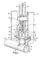
- FIG. 1 apparatus for drilling an aperture in a polyethylene pipe 10 is shown seated on a portion of the pipe 10 and anchored against two battens 12 and 14, the latter representing the sides of an excavated shaft of approximately 0.5 metres diameter which has been bored to expose the pipe 10.
- the apparatus includes a drilling jig comprising a drill housing 16 and a saddle 18 seated on the surface of the pipe 10.
- the battens 12 and 14 are placed against the walls of the shaft to provide a solid support for the feet of the rams 24 and 26, but it will be understood that depending on the soil conditions this extra support may not be needed.
- a metal or concrete pipe section may be positioned in the shaft to provide the necessary support.
- the rams 24 and 26 may have screw extensions to allow for shafts of different-diameters. They are connected by a pair of fluid supply pipes 28 and 30-to a pump (not shown) at ground level. When the rams 24 and 26 are pressurised their upward inclination results in a net downward force on to the housing 16, pushing the saddle 18 onto the pipe 10, thereby providing a firm location while the pipe is being drilled.
- Tubular manipulating rods 32 and 34 located in brackets 36 and 38 on the sides of the housing 16 extend to ground level to allow an operator to lower the apparatus onto the pipe 10 and position the housing 16 over the required drilling location before the rams 24 and 26 are operated.
- the rods 32 and 34 are rotatable in the brackets, and have threaded ends secured in the lower brackets 38.
- the housing 16 contains a rotatable drill block 40 to which is mounted a cup drill (described below with reference to Fig. 4).
- a square section drive shaft 42 is located in the drill block 40 and extends upwardly to a drive motor (not shown) at ground level.
- a universal joint 45 provides for inclination of the upper portion of the shaft, and a telescopic connection (not shown) may be included if required.
- a drill feed device is attached to the shaft 42 as shown.
- the device comprises a bridge section 44 attached to the manipulating rods 32 and 34 and having an internally threaded hole for guiding a threaded portion 46 of the drive shaft 42.
- a collar 48 fixed to the shaft 42 is coupled to a ring 50 connected to a pair of stays 52 and 54 to prevent the drill block 40 from dropping into pipe 10 should the threaded portion 46 pass completely out of the bridge section 44.
- the excavated shaft may be 3 metres deep.
- the pipe 10 is a polyethylene pipe previously inserted in an existing earthenware sewage pipe which has been broken away at the bottom of the shaft to expose the pipe 10.
- the apparatus may be used typically to drill a hole approximately 100 mm in diameter in the wall of the pipe 10 so that a branching pipe can be inserted and bonded to the sides of the hole.
- the sequence of operations for drilling the hole may be as follows:-
- the feed device, the drill block 40 and the drill can be removed prior to depressurising the rams so that the housing 40 can be used as a guide for locating the branch pipe in the drilled hole.
- the rams 24 and 26 and the manipulating rods 32 and 34 may be mounted on a single pair of enlarged brackets 56 and 58, the rods 32 and 34 being received in threaded holes 60 and 62.
- the rams 24 and 26 are each hinged about a horizontal axis defined by a hinge pin 64 so that they can be retracted when the housing 16 is being raised or lowered.
- the brackets 56 and 58 have projecting stops 66 and 68 which each abut the side of the respective ram to set the upward inclination of the rams at 15 0 in their operative position.
- Slots 70 and 72 are provided for circumferential adjustment of the ram position when, for example, the pipe 10 is not centrally located in the excavated shaft.
- Fig. 4 also illustrates additional features not shown in Figs. 1 to 3.
- the housing.16 rests on the saddle 18 which is shaped to correspond to the outer surface of the pipe 10.
- the saddle 18 is detachable from the housing 16 to allow replacement by a different saddle shaped to correspond to a pipe of another diameter.
- the housing 16 may also be rotated on the saddle since the saddle retaining bolts 74 are located in a groove 76 in the housing.
- the drill block 40 is rotatable inside the housing 16 and is in contact with a replaceable liner 78 of corresponding diameter.
- the drill for cutting the aperture 79 in the pipe 10 is in two parts, which are (i) a pilot drill 80 and (ii) a cup drill 82, the latter being shown at a position corresponding to an intermediate stage in the drilling process.
- the pilot drill 80 is threaded at its upper end and receive in a threaded bore in the drill block 40.
- a flange 84 serves to secure the cup drill 82 to the underside of the drill block 40, rotation of the cup drill 82 relative to the block 40 being prevented by the dowel 86.
- a small spring loaded pip 88 projects from the side of the drill. The purpose of this is to prevent the waste coupon cut away from the pipe 10 by the cup drill 82 from falling into the pipe 10 when drilling is complete.
- a variety of different cup drill sizes can be . .accommodated, up to a maximum diameter corresponding to the internal diameter of the liner 78.
- the drive shaft 42 includes a second universal joint 90.
- Fig. 4 also illustrates an alternative, dual threaded drill feed device comprising a first threaded sleeve 92 having a square hole at its upper end so that it rotates with the drive shaft 42, and a second non-rotatable threaded sleeve 94 coupled to a rotatable collar 96 fixed to the drive shaft.
- the first sleeve 92 is mounted in a threaded ring 98 fitted'to the bridge section 44 so that, as the drive shaft 42 rotates in clockwise direction, the sleeve 92 moves towards the pipe 10.
- the first sleeve 92 is also internally threaded to receive the external thread of the second sleeve 94.
- the thread on sleeve 94 is finer in pitch than the external thread of sleeve 92.
- the first sleeve 92 rotates it draws the second sleeve 94 upwards relative to the first sleeve 92, but the net effect is that the second sleeve 94 moves towards the pipe 10 at a relatively slow rate due to the combined effect of the two threads.
- This allows a relatively slow feed rate to be obtained without reducing the speed of rotation of the drive shaft, and without reducing the pitch of a single thread feed device as shown in Fig. 1 to an impracticable degree.
- Stays 52 and 54 prevent rotation of the second sleeve 94, and slide in the bridge 44 against springs 100 and 102 to maintain the two sleeves in contact with each other when the ends of threads are reached.
- Additional feed travel can be achieved by providing two spaced attachment points on the housing 16 for each manipulating rod 32 and 34.
- the manipulating rods are rotatable in the bridge section 44 and are threaded at their lower ends.
- both upper and lower attachment points are threaded to receive the rod ends.
- this device has a pair of pneumatic or hydraulic rams 112 and 114 mounted in the bridge section 44, the piston rods 116 and 118 being attached to a cross bar 120 coupled to the drive shaft 42.
- the cross bar 120 slides on the manipulating rods 32 and 34.
Landscapes
- Engineering & Computer Science (AREA)
- Mechanical Engineering (AREA)
- Processing Of Stones Or Stones Resemblance Materials (AREA)
- Earth Drilling (AREA)
- Drilling And Boring (AREA)
Applications Claiming Priority (2)
| Application Number | Priority Date | Filing Date | Title |
|---|---|---|---|
| GB8104619 | 1981-02-13 | ||
| GB8104619 | 1981-02-13 |
Publications (2)
| Publication Number | Publication Date |
|---|---|
| EP0058517A2 true EP0058517A2 (de) | 1982-08-25 |
| EP0058517A3 EP0058517A3 (de) | 1983-05-11 |
Family
ID=10519702
Family Applications (1)
| Application Number | Title | Priority Date | Filing Date |
|---|---|---|---|
| EP82300672A Ceased EP0058517A3 (de) | 1981-02-13 | 1982-02-11 | Fernbedientes Bohrgerät |
Country Status (5)
| Country | Link |
|---|---|
| EP (1) | EP0058517A3 (de) |
| AU (1) | AU8048182A (de) |
| CA (1) | CA1178830A (de) |
| GB (1) | GB2092925B (de) |
| ZA (1) | ZA82957B (de) |
Cited By (11)
| Publication number | Priority date | Publication date | Assignee | Title |
|---|---|---|---|---|
| NL8702611A (nl) * | 1987-11-02 | 1989-03-01 | Rotterdam Gemeente | Werkwijze en inrichting voor het controleren van de toestand van betonnen rioolbuizen. |
| EP1048885A3 (de) * | 1999-04-27 | 2002-04-03 | Friatec Aktiengesellschaft | Vorrichtung zur Herstellung einer Verbindung einer Armatur mit einem Rohr |
| SG89416A1 (en) * | 2000-08-31 | 2002-06-18 | Nitto Kohki Co | Boring machine |
| CN101985180A (zh) * | 2010-11-30 | 2011-03-16 | 济南沃德汽车零部件有限公司 | 气门挺杆漏油孔专用钻床 |
| CN104475804A (zh) * | 2014-12-03 | 2015-04-01 | 江苏武进不锈股份有限公司 | 棒材钻孔装置 |
| CN104912187A (zh) * | 2015-06-16 | 2015-09-16 | 安庆市华鑫重工股份有限公司 | 一种下水道除污抓斗专用径向锁紧装置 |
| CN108856809A (zh) * | 2018-09-11 | 2018-11-23 | 詹哲品 | 一种镀锌钢管多角度钻斜孔装置及镀锌钢管钻斜孔工艺 |
| CN111660115A (zh) * | 2020-07-07 | 2020-09-15 | 新昌县益旭龙机械科技有限公司 | 安装有快速调节定位的数控加工用夹具设备 |
| CN113236891A (zh) * | 2021-05-21 | 2021-08-10 | 中国十七冶集团有限公司 | 一种不间断供水管线支管改造装置及使用方法 |
| CN116141012A (zh) * | 2023-03-24 | 2023-05-23 | 无方科技(浙江)有限公司 | 基于槽体开设的真空泵加工装置及加工方法 |
| CN119216633A (zh) * | 2024-12-04 | 2024-12-31 | 山建大工程技术(山东)有限公司 | 一种消防施工用管道切割开孔设备 |
Families Citing this family (8)
| Publication number | Priority date | Publication date | Assignee | Title |
|---|---|---|---|---|
| GB2222539B (en) * | 1986-01-30 | 1990-11-14 | Thames Water Authority | A method of attaching a saddle member |
| EP0235917A1 (de) * | 1986-01-30 | 1987-09-09 | The Thames Water Authority | Anbohren von unterirdischen Leitungen |
| CA2313573C (en) | 2000-07-06 | 2004-02-10 | David Albert Nyhuis | Drilling apparatus for tapping into a fluid containing vessel |
| RU2197362C2 (ru) * | 2001-04-13 | 2003-01-27 | Государственное федеральное унитарное предприятие Центральное конструкторское бюро машиностроения | Резцовая головка для вырезки дисков в металлических листах |
| GB0110821D0 (en) * | 2001-05-03 | 2001-06-27 | Clear Well Subsea Ltd | Making Connections to pipes uner pressure |
| US8167519B2 (en) | 2008-03-18 | 2012-05-01 | Meco Constructors, Inc. | Portable coring machine |
| NO20171129A1 (en) * | 2017-07-07 | 2019-01-08 | Rune Gjervoldstad | A machining arrangement and a method for attachment to and machining a working piece |
| CN116713510B (zh) * | 2023-08-03 | 2024-03-12 | 福建省锦强机械制造有限公司 | 一种螺栓生产用螺杆头部开孔装置及其开孔方法 |
Family Cites Families (6)
| Publication number | Priority date | Publication date | Assignee | Title |
|---|---|---|---|---|
| US2800812A (en) * | 1955-06-14 | 1957-07-30 | Mueller & Co | Shell cutter assembly |
| GB1035926A (en) * | 1962-05-04 | 1966-07-13 | Wolstan C Ginies Entpr Proprie | Earth drilling machine |
| US3293952A (en) * | 1963-07-30 | 1966-12-27 | Philip R Fairbanks | Pipe hole cutter and method |
| CH459285A (de) * | 1965-11-03 | 1968-07-15 | Wirth Alfred & Co Kg | Verfahren und Maschine zum Vortreiben eines Tunnels oder Stollens |
| US3922107A (en) * | 1973-05-31 | 1975-11-25 | Dwight W Fowler | Sewer tapping method and apparatus |
| EP0002291A3 (de) * | 1977-11-16 | 1979-07-25 | VANDAELE GEBROEDERS personenvennootschap met beperkte aansprakelijkheid | Hydraulische Kernbohrvorrichtung |
-
1982
- 1982-02-10 GB GB8203842A patent/GB2092925B/en not_active Expired
- 1982-02-11 EP EP82300672A patent/EP0058517A3/de not_active Ceased
- 1982-02-15 ZA ZA82957A patent/ZA82957B/xx unknown
- 1982-02-15 CA CA000396278A patent/CA1178830A/en not_active Expired
- 1982-02-15 AU AU80481/82A patent/AU8048182A/en not_active Abandoned
Cited By (14)
| Publication number | Priority date | Publication date | Assignee | Title |
|---|---|---|---|---|
| NL8702611A (nl) * | 1987-11-02 | 1989-03-01 | Rotterdam Gemeente | Werkwijze en inrichting voor het controleren van de toestand van betonnen rioolbuizen. |
| EP0315277A1 (de) * | 1987-11-02 | 1989-05-10 | Gemeente Rotterdam, Gemeentewerken, Beheer En Onderhoud Kunstwerken/Cwp | Verfahren und Vorrichtung zur Prüfung von erdverlegten Kanalisationsrohren aus Beton |
| EP1048885A3 (de) * | 1999-04-27 | 2002-04-03 | Friatec Aktiengesellschaft | Vorrichtung zur Herstellung einer Verbindung einer Armatur mit einem Rohr |
| SG89416A1 (en) * | 2000-08-31 | 2002-06-18 | Nitto Kohki Co | Boring machine |
| CN101985180A (zh) * | 2010-11-30 | 2011-03-16 | 济南沃德汽车零部件有限公司 | 气门挺杆漏油孔专用钻床 |
| CN104475804A (zh) * | 2014-12-03 | 2015-04-01 | 江苏武进不锈股份有限公司 | 棒材钻孔装置 |
| CN104912187A (zh) * | 2015-06-16 | 2015-09-16 | 安庆市华鑫重工股份有限公司 | 一种下水道除污抓斗专用径向锁紧装置 |
| CN108856809A (zh) * | 2018-09-11 | 2018-11-23 | 詹哲品 | 一种镀锌钢管多角度钻斜孔装置及镀锌钢管钻斜孔工艺 |
| CN108856809B (zh) * | 2018-09-11 | 2020-01-21 | 溧阳市储丰钢板仓设备制造工程有限公司 | 一种镀锌钢管多角度钻斜孔装置及镀锌钢管钻斜孔工艺 |
| CN111660115A (zh) * | 2020-07-07 | 2020-09-15 | 新昌县益旭龙机械科技有限公司 | 安装有快速调节定位的数控加工用夹具设备 |
| CN113236891A (zh) * | 2021-05-21 | 2021-08-10 | 中国十七冶集团有限公司 | 一种不间断供水管线支管改造装置及使用方法 |
| CN116141012A (zh) * | 2023-03-24 | 2023-05-23 | 无方科技(浙江)有限公司 | 基于槽体开设的真空泵加工装置及加工方法 |
| CN116141012B (zh) * | 2023-03-24 | 2024-04-23 | 昊华海通(北京)国际贸易有限公司 | 基于槽体开设的真空泵加工装置及加工方法 |
| CN119216633A (zh) * | 2024-12-04 | 2024-12-31 | 山建大工程技术(山东)有限公司 | 一种消防施工用管道切割开孔设备 |
Also Published As
| Publication number | Publication date |
|---|---|
| GB2092925B (en) | 1984-08-30 |
| EP0058517A3 (de) | 1983-05-11 |
| GB2092925A (en) | 1982-08-25 |
| CA1178830A (en) | 1984-12-04 |
| ZA82957B (en) | 1983-01-26 |
| AU8048182A (en) | 1982-08-19 |
Similar Documents
| Publication | Publication Date | Title |
|---|---|---|
| EP0058517A2 (de) | Fernbedientes Bohrgerät | |
| US10697246B2 (en) | Shaft enlargement arrangement for a boring system | |
| EP0124658B1 (de) | Firstbolzenmaschine | |
| US5403122A (en) | Process, in particular to install sewer pipes and a device to carry out the process | |
| KR100497814B1 (ko) | 굴착 장치 및 굴착 방법 | |
| US6244783B1 (en) | Widening apparatus | |
| ATE305995T1 (de) | Einrichtung und methode zum erdbohren | |
| US3961673A (en) | Drilling apparatus | |
| EP0412092B1 (de) | Vorrichtung und verfahren zur herstellung unterirdischer leitungen | |
| NO169608B (no) | Innretning for aa tilveiebringe et monteringsroer eller stikkledning for et nedgravet hovedroer | |
| EP1497503B1 (de) | Verfahren und system zur anordnung mindestens eines gründungselements im boden | |
| JPH1089538A (ja) | 導管の接続方法 | |
| JPH10159127A (ja) | 地面に深い溝を掘削する装置および方法 | |
| EP0580264A1 (de) | Verfahren und Grabvorrichtung zur Herstellung von Schlitzwänden | |
| US4102413A (en) | Rock drilling apparatus and method | |
| JP7700191B2 (ja) | 水中掘削装置および水中でケーシングされた掘削孔を形成する方法 | |
| NO331324B1 (no) | Fremgangsmåter og apparat for overskjæring av nestede rørstrenger | |
| CN100360762C (zh) | 定向钻孔组件及定向钻孔设备 | |
| US3610345A (en) | Earth boring machine carriage with detachable pusher ring and power frames | |
| JP2003155893A (ja) | 推進機 | |
| US10092962B2 (en) | Method and apparatus for drilling ports in utility access shafts or manholes | |
| WO1997002405A1 (en) | Drilling apparatus | |
| Committee on Construction Equipment and Techniques | Trenchless excavation construction methods: classification and evaluation | |
| AU6294096A (en) | Drilling apparatus | |
| JPH07292754A (ja) | 既設下水管への分岐取水管取り付け方法 |
Legal Events
| Date | Code | Title | Description |
|---|---|---|---|
| PUAI | Public reference made under article 153(3) epc to a published international application that has entered the european phase |
Free format text: ORIGINAL CODE: 0009012 |
|
| AK | Designated contracting states |
Designated state(s): AT BE CH DE FR IT NL SE |
|
| PUAL | Search report despatched |
Free format text: ORIGINAL CODE: 0009013 |
|
| AK | Designated contracting states |
Designated state(s): AT BE CH DE FR IT LI NL SE |
|
| 17P | Request for examination filed |
Effective date: 19831109 |
|
| STAA | Information on the status of an ep patent application or granted ep patent |
Free format text: STATUS: THE APPLICATION HAS BEEN REFUSED |
|
| 18R | Application refused |
Effective date: 19850707 |