EP0058983B1 - Dispositif pour affûter des carres de ski - Google Patents
Dispositif pour affûter des carres de ski Download PDFInfo
- Publication number
- EP0058983B1 EP0058983B1 EP82101341A EP82101341A EP0058983B1 EP 0058983 B1 EP0058983 B1 EP 0058983B1 EP 82101341 A EP82101341 A EP 82101341A EP 82101341 A EP82101341 A EP 82101341A EP 0058983 B1 EP0058983 B1 EP 0058983B1
- Authority
- EP
- European Patent Office
- Prior art keywords
- motor
- housing
- accordance
- ski
- guide surface
- Prior art date
- Legal status (The legal status is an assumption and is not a legal conclusion. Google has not performed a legal analysis and makes no representation as to the accuracy of the status listed.)
- Expired
Links
- 230000006835 compression Effects 0.000 claims abstract description 7
- 238000007906 compression Methods 0.000 claims abstract description 7
- 229910000831 Steel Inorganic materials 0.000 claims description 15
- 239000010959 steel Substances 0.000 claims description 15
- 239000004575 stone Substances 0.000 claims description 9
- 239000000463 material Substances 0.000 claims description 7
- 238000013461 design Methods 0.000 claims description 5
- 230000004308 accommodation Effects 0.000 claims 2
- 238000010276 construction Methods 0.000 claims 1
- 230000013011 mating Effects 0.000 claims 1
- 238000000034 method Methods 0.000 description 11
- 239000000428 dust Substances 0.000 description 5
- 230000006378 damage Effects 0.000 description 3
- 230000001681 protective effect Effects 0.000 description 2
- 230000000284 resting effect Effects 0.000 description 2
- 229910001335 Galvanized steel Inorganic materials 0.000 description 1
- 230000002411 adverse Effects 0.000 description 1
- XAGFODPZIPBFFR-UHFFFAOYSA-N aluminium Chemical compound [Al] XAGFODPZIPBFFR-UHFFFAOYSA-N 0.000 description 1
- 229910052782 aluminium Inorganic materials 0.000 description 1
- 238000013459 approach Methods 0.000 description 1
- 238000011109 contamination Methods 0.000 description 1
- 230000001419 dependent effect Effects 0.000 description 1
- 230000000694 effects Effects 0.000 description 1
- 239000008397 galvanized steel Substances 0.000 description 1
- 238000010438 heat treatment Methods 0.000 description 1
- 238000004519 manufacturing process Methods 0.000 description 1
- 238000013021 overheating Methods 0.000 description 1
- 230000002093 peripheral effect Effects 0.000 description 1
- 230000036316 preload Effects 0.000 description 1
- 238000011160 research Methods 0.000 description 1
- 238000012360 testing method Methods 0.000 description 1
Images


Classifications
-
- B—PERFORMING OPERATIONS; TRANSPORTING
- B24—GRINDING; POLISHING
- B24B—MACHINES, DEVICES, OR PROCESSES FOR GRINDING OR POLISHING; DRESSING OR CONDITIONING OF ABRADING SURFACES; FEEDING OF GRINDING, POLISHING, OR LAPPING AGENTS
- B24B3/00—Sharpening cutting edges, e.g. of tools; Accessories therefor, e.g. for holding the tools
- B24B3/006—Sharpening cutting edges, e.g. of tools; Accessories therefor, e.g. for holding the tools for edges of skis, snowboards or the like
-
- A—HUMAN NECESSITIES
- A63—SPORTS; GAMES; AMUSEMENTS
- A63C—SKATES; SKIS; ROLLER SKATES; DESIGN OR LAYOUT OF COURTS, RINKS OR THE LIKE
- A63C11/00—Accessories for skiing or snowboarding
- A63C11/04—Accessories for skiing or snowboarding for treating skis or snowboards
- A63C11/06—Edge-sharpeners
Definitions
- the invention relates to a device for sharpening ski edges with a motor driving a rotating grinding element and a motor receiving housing with a guide surface that can be supported on the respective ski with stop elements, the motor of which is arranged in the housing with an at least substantially perpendicular shaft to the guide surface, the free of which End is designed for releasable attachment of a grinding wheel.
- file-like devices which are equipped with a guide which is used at the same time for clamping the file.
- Such devices have the disadvantages in particular that the sharpening work requires considerable effort, is time-consuming and if the device slips off the sliding surface of the skis can be severely damaged.
- files of this type become blunt very quickly, since the ski edges harden strongly in precisely those places where there were strong blows against stones, and these hard areas, which can hardly be removed, result in the file becoming unsharp.
- a device for grinding the steel edges of skis is known with a grinding body driven by a drive motor and with a guide body to be attached to the ski, which is fastened to a basket slidably connected to the housing of the drive motor and which is shown in FIG
- Feed direction of the device running guide rail is formed with mutually perpendicular guide surfaces.
- An opening for the passage of the grinding wheel is provided in the guide surface of the guide rail which is aligned parallel to the grinding plane.
- a chuck is attached to the shaft of the drive motor to accommodate the grinding wheel.
- a device for grinding and refreshing ski body side surfaces which consists of a slide guided on the ski and a movable and adjustable support for a cylindrical grinding wheel which is parallel and parallel to the side surface edge runs essentially perpendicular to the longitudinal axis of the side surface.
- the grinding wheel is driven by a flexible hollow shaft.
- the support receiving the grinding wheel hollow shaft is pivotally mounted about an axis extending perpendicular to the longitudinal axis of the ski and is held against a settable stop by a tension spring.
- the object of the invention is to design a device of the type mentioned at the outset in a compact and simple manner and to ensure that it is suitable for one-handed operation and can be handled without problems without special expertise, and also enables frequent sharpening of the edges due to a prescribably low material removal and without the risk local edge overheating and without any risk for the sliding surface of the skis can be used.
- the motor is pivotally supported to a limited extent about an axis extending in the longitudinal direction of the guide surface or in the longitudinal direction of the ski, that a compression spring is provided between the pivotably mounted motor and the housing, and that the support members on The device for the guide surface runs vertically and can be supported laterally on the ski, the distance to a plane perpendicular to the pivot bearing axis being substantially equal to the radius of the grinding wheel.
- the swivel bearing axis is preferably provided in the region of the end of the motor shaft opposite the grinding wheel, wherein according to a particularly advantageous embodiment of the invention, a joint part is fastened to the swivel bearing axis on the upper motor flange and a guide and / or stop piece is attached to the lower motor flange, so that an exact Motor and thus grinding wheel guidance results in little effort.
- the grinding wheel has a support part designed as a screw sleeve and can be screwed onto the free end of the motor shaft which is provided with a corresponding thread, the end of the motor shaft which is opposite the grinding wheel and is provided with a slot or the like via an opening in the housing for a tool is accessible.
- the grinding wheel has a central region which is reinforced in the axial direction and receives the support part, and a flat cylindrical edge region whose axial dimension is only slightly larger than the height of the steel edge to be sharpened.
- the flat cylindrical edge area represents the actual grinding part of the wheel. Occasional grinding wheel wear or dirt can - if it is not preferred to replace the grinding wheel - be removed by using a dressing stone.
- the compression spring generating the preload is guided on or in a housing extension and engages in the area of the center of the pivotably mounted motor.
- the pretensioning force is fixed, but in principle an adjustment option accessible to the user can also be provided.
- the housing has a cup-shaped receiving space, the circumferential ring wall of which is metallic at least on a partial area corresponding to the area where the grinding chips hit.
- the metallic section preferably consists of an insert piece which is fitted into a corresponding recess in the housing and fixed by means of screws, it being particularly advantageous to design this insert piece in such a way that it simultaneously forms a wear-resistant stop element.
- the guide surface that comes into contact with the ski tread preferably does not lie on the entire surface of the ski tread, but instead linear structures are provided in the longitudinal direction, which on the one hand increase the ease of sliding movement of the device and on the other hand lead to the tread being contaminated by Grinding dust that could otherwise be pressed into the tread is counteracted. Practice has shown that with this type of device there is practically no tread contamination from grinding dust.
- the above-mentioned dressing stone is preferably guided in a recess in the housing, a U-shaped recess, which extends transversely to the longitudinal direction, being preferably provided in the guide surface for the positive reception of the dressing stone. If you notice wear or soiling of the grinding wheel, the dressing stone is placed in this holder and pressed lightly against this grinding wheel while the grinding wheel is running, which immediately creates optimal conditions again.
- a hand-held device which consists of a guide surface 3 provided on a guide plate, which is placed on the ski running surface, and a housing 4 in which a drive motor 5 is located, on the shaft 6 of which a grinding wheel 7 is fastened.
- This grinding wheel is preferably arranged such that the lower edge of this grinding wheel protrudes only slightly beyond the edge side facing away from the running surface of the ski.
- the motor 7 is pivotally mounted with respect to the housing 4, namely by means of an elastic holding element 8 which is connected to the upper motor flange on the one hand and to the housing 4 on the other hand.
- the end of the motor opposite the elastic fastening is guided by means of a guide member 9 in such a way that the motor can perform a swiveling movement transversely to the ski 1, but there is no mobility in the longitudinal direction of the ski.
- a corresponding guide recess for the link 9 is provided in the housing base 10.
- the motor 5 is biased at least by a spring 11 in such a way that the force of this spring 11 must be overcome when the grinding wheel 7 is pressed against the edge 2.
- the spring force can be adjustable, but is preferably set at the factory to a fixed value that ensures the optimally desired material removal.
- a microswitch 12 is also provided in the housing 4 and is mounted in the swivel path of the motor in such a way that the motor can only be switched on when its axis is essentially vertical.
- this microswitch is not an absolute necessity, since practice has shown that motor deflections of 2 to 3 °, as indicated in FIG. 1 and which can result from grinding wheel wear, do not have a negative effect on edge sharpening.
- the device is switched on using a switch 13 indicated in the drawing.
- the maximum running time of the motor can be limited by means of a thermal switch.
- the device is guided via stop members which are located on both sides of the grinding wheel 7.
- a cover 17 surrounds the grinding wheel 7 at least partially and ensures that no grinding chips can be thrown outwards in a disruptive manner during the grinding process.
- the exact alignment of the device with respect to the ski can also be precisely specified via sensor switches, in particular microswitches, since such sensor switches can be assigned to both the guide surface 3 and the lateral stop members, and provision can be made that these sensor switches only enable the drive motor to be supplied when the optimal position of the device is maintained.
- sensor switches in particular microswitches
- the device can be easily and precisely guided by hand due to its design, such additional devices are generally not absolutely necessary.
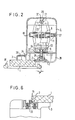
- FIGS. 2 and 3 show a preferred embodiment of a device according to the invention during the process of grinding the steel edge 2 of the ski 1.
- an existing ski brake 18, indicated schematically in the drawing must either be removed or brought into the retracted position, which can be done by clamping or simply by attaching a shoe to the binding.
- the motor 5, which is arranged upright in the housing 4, is pivotable and mounted transversely to the longitudinal direction of the ski via a joint part 21 which is connected to the upper motor flange.
- the associated swivel bearing axis 20 accordingly extends in the longitudinal direction of the device or ski 1.
- the motor On the grinding wheel side, the motor is guided in its swivel plane via a guide piece 24 fastened to the lower motor flange.
- a seal 37 consisting of a felt strip prevents dirt and grinding dust from entering the interior of the housing.
- a compression spring 11 is arranged, which sits on a housing extension 27 and engages approximately centrally on the motor 5. This spring 11 makes the force with which the grinding wheel 7 is pressed against the edge 2 during the grinding process, regardless of the respective operator.
- the device rests on the one hand on the running surface of the ski 1 via the guide surface 3 and on the other hand via stop members 15, 16, which can be seen in particular in FIGS. 4 and 5, on the respective side surface of the ski or the steel edge, which means that adjacent contact elements, the contact pressure is generated solely by the compression spring 11.
- the guide surface 3, which extends over at least 60% of the width of the ski tread, is preferably designed in such a way that only line contact results between the device and the ski tread, specifically via webs 34, which extend in the longitudinal direction of the tread or the ski .
- the top of the guide part 3 is expediently designed as a grooved surface 36, as a result of which the second hand of the operator finds a secure hold.
- a thermostat 19 is preferably installed, which switches the motor off after a predetermined operating time. If the motor has cooled down sufficiently after a corresponding standstill, the device can be started again. It is possible to indicate the operational readiness of the device via a signal lamp or LED.
- the grinding wheel 7 has a central region which is reinforced in the axial direction and receives a screw-sleeve-shaped carrier part 25 and a flat cylindrical edge region whose axial dimension is, for example, 5 mm, while the usual height of the steel edges is approximately 3 mm.
- the protrusion of the grinding wheel 7 over the guide surface resting on the ski tread is selected so that the lower edge of the grinding wheel is approximately flush with the steel edge or extends slightly beyond it.
- the diameter of the wheel becomes smaller due to wear of the grinding wheel, which results in a slight inclination of the motor, which is a maximum of 3 °. A further stop of the motor is prevented by a stop. However, this inclination does not adversely affect the grinding result.
- the housing 4 consists of two half-shells, with the guide part 3 with the guide surface resting on the ski running surface and the lateral stop members 15, 16 located on both sides of the grinding wheel in the longitudinal direction of the ski being molded onto one half-shell, while a grinding wheel cover hood 28 is formed on the other half-shell can be snapped on.
- FIG. 3 shows the handle 29 molded onto the housing 4 or the two half-shell parts, at the free end of which a cable entry 30 is provided.
- a pushbutton switch 31 is provided adjacent to the housing 4 and can be conveniently operated with the index finger.
- the guide surface 3 extends in the longitudinal direction of the device into the region of the handle 29 and thus enables particularly safe handling of the device.
- the articulated part 21 fastened to the upper motor flange 22 is held via the swivel bearing axis parts 20 in receiving bearings 38 formed by approaches of the housing half-shells.
- the motor axis 6, which preferably has a slot, is accessible via an opening 26 in the upper housing wall, so that this shaft 6 can be turned or held in place by means of a screwdriver if a grinding wheel 7 has to be fastened or replaced.
- a guide piece 24 is screwed, which - as can be seen in FIG. 2 - guides the motor 5 in its defined pivoting plane and limits the maximum deflections.
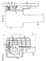
- the bottom view of the device according to Fig. 4 shows an embodiment of the guide surface 3, the receiving space 32 for the grinding wheel 7 and the stop members 15, 16.
- the guide surface 3 is structured in a network-like manner, preferably only the longitudinally extending webs 34 coming into contact with the running surface of the respective ski, while the transverse webs are set back somewhat, on the one hand to ensure the lowest possible sliding resistance and on the other to avoid that dirt or dirt getting onto the tread of the ski is pressed into the tread while the device is being guided lengthways. Practical tests have shown, however, that even if all the webs rest on the tread, the risk of soiling of the covering is minimal.
- the lattice-like structure of the guide surface 3 also leads to high stability with a low weight.
- the cup-shaped receiving space 32 for the grinding wheel 7 is delimited by corresponding ring walls of the two housing half-shells.
- the pot wall is formed by a protective insert 33, which preferably consists of an aluminum die-cast part, which is inserted and screwed into a suitable recess.
- This insert 33 is simultaneously provided with a strip-shaped stop member 16 which is aligned with the stop member 15 located on the other side of the grinding wheel 7. Since these stop members come to rest against the steel edges in practical operation, it is advantageous to manufacture these members from wear-resistant material.
- the covering hood 28 which represents protection against contact and grinding dust, is designed as a part which can be snapped onto a housing half.
- the corresponding snap-lock connections can be seen in Fig. 4.
- a cross-sectionally U-shaped recess 35 in the guide surface 3 runs transversely to the longitudinal direction of this guide surface and at the height of the grinding wheel 7.
- This recess 35 serves to receive and guide a dressing stone, not shown, which is inserted into this recess 35 and against the running grinding wheel 7 this disc can be pushed. In this way, problem-free and quick dressing of the grinding wheel 7 is possible.
- the side view according to FIG. 5 shows the design and arrangement of the stop members 15, 16.
- the stop member 15 is formed by a steel fencing plate suitably inserted into a corresponding recess in the plastic housing, which is screwed to the housing above the area opposite the steel edge 2.
- the stop member 16 consists of a shoulder of the insert 33, which is also screwed to the housing. 4 and 5 clearly show that, based on the overall device size, there are sufficiently large guide surfaces available both in the ski plane and perpendicular to it to enable the user to move the device quickly and continuously along the ski without any tendency to tip over.
- the sectional view according to FIG. 6 shows a cross section of the die-cast part 33 with a stop element 16 formed thereon, which comes to bear against the steel edge 2. It can be clearly seen here that the stop element 16 only has to extend slightly beyond the steel edge 2 in order to ensure reliable guidance of the device. Of course, this also applies to the stop element 15 shown in FIG. 5.
- the device is preferably placed in the region of the ski ends with the grinding wheel running and then quickly led along the ski. Since the resulting material removal is deliberately kept comparatively low, it may be necessary to repeat the continuous grinding process several times if the edges are very rounded. Any adjustments or readjustments are not required on the device. Only if the grinding wheel is badly worn or dirty, the wheel should be removed using a dressing stone.
Landscapes
- Engineering & Computer Science (AREA)
- Mechanical Engineering (AREA)
- Finish Polishing, Edge Sharpening, And Grinding By Specific Grinding Devices (AREA)
- Grinding Of Cylindrical And Plane Surfaces (AREA)
- Facsimile Image Signal Circuits (AREA)
Claims (19)
Priority Applications (1)
| Application Number | Priority Date | Filing Date | Title |
|---|---|---|---|
| AT82101341T ATE16355T1 (de) | 1981-02-25 | 1982-02-22 | Geraet zum schaerfen von skikanten. |
Applications Claiming Priority (2)
| Application Number | Priority Date | Filing Date | Title |
|---|---|---|---|
| DE19813107080 DE3107080A1 (de) | 1981-02-25 | 1981-02-25 | Geraet zum schaerfen von skikanten |
| DE3107080 | 1981-02-25 |
Publications (2)
| Publication Number | Publication Date |
|---|---|
| EP0058983A1 EP0058983A1 (fr) | 1982-09-01 |
| EP0058983B1 true EP0058983B1 (fr) | 1985-11-06 |
Family
ID=6125728
Family Applications (1)
| Application Number | Title | Priority Date | Filing Date |
|---|---|---|---|
| EP82101341A Expired EP0058983B1 (fr) | 1981-02-25 | 1982-02-22 | Dispositif pour affûter des carres de ski |
Country Status (3)
| Country | Link |
|---|---|
| EP (1) | EP0058983B1 (fr) |
| AT (1) | ATE16355T1 (fr) |
| DE (2) | DE3107080A1 (fr) |
Cited By (1)
| Publication number | Priority date | Publication date | Assignee | Title |
|---|---|---|---|---|
| AT409090B (de) * | 1996-07-25 | 2002-05-27 | Wintersteiger Gmbh & Co | Vorrichtung zum nachbearbeiten einer stahlkante eines skis |
Families Citing this family (5)
| Publication number | Priority date | Publication date | Assignee | Title |
|---|---|---|---|---|
| DE59003407D1 (de) * | 1989-06-16 | 1993-12-16 | Rudolf Tschan | Handgerät zum Bearbeiten von Skikanten. |
| DE4413935C2 (de) * | 1994-04-21 | 1996-05-30 | Willi Leweke | Skikanten-Schleifgerät |
| DE4443625A1 (de) * | 1994-12-08 | 1996-06-13 | Manfred Ullrich | Skikanten-Schleifgerät |
| US6702656B1 (en) * | 2002-09-16 | 2004-03-09 | Edgetune, Inc. | Snow ski and snowboard edge sharpening device |
| AT7247U1 (de) * | 2003-11-07 | 2004-12-27 | Schachermayer Alfred | Vorrichtung zum händischen schleifen und schärfen von laufflächenkanten |
Family Cites Families (5)
| Publication number | Priority date | Publication date | Assignee | Title |
|---|---|---|---|---|
| US3412508A (en) * | 1966-02-16 | 1968-11-26 | Liguori J. Schell Jr. | Ski sharpener |
| CH483294A (de) * | 1968-11-04 | 1969-12-31 | Hess & Cie | Skikantenschleifmaschine |
| FR2105671A5 (fr) * | 1970-09-04 | 1972-04-28 | Gerbelot Pierre | |
| DE2308676A1 (de) * | 1973-02-22 | 1974-09-05 | Miro Cujovic | Handschleifmaschine zum schleifen von eine scharfe kante bildenden flankenflaechen, insbesondere an auf der skiunterseite angebrachten stahlkantenleisten |
| AT361358B (de) * | 1979-03-30 | 1981-03-10 | Kopeinig Alois | Vorrichtung zum schleifen der stahlkanten von skiern |
-
1981
- 1981-02-25 DE DE19813107080 patent/DE3107080A1/de not_active Withdrawn
-
1982
- 1982-02-22 EP EP82101341A patent/EP0058983B1/fr not_active Expired
- 1982-02-22 AT AT82101341T patent/ATE16355T1/de not_active IP Right Cessation
- 1982-02-22 DE DE8282101341T patent/DE3267222D1/de not_active Expired
Cited By (1)
| Publication number | Priority date | Publication date | Assignee | Title |
|---|---|---|---|---|
| AT409090B (de) * | 1996-07-25 | 2002-05-27 | Wintersteiger Gmbh & Co | Vorrichtung zum nachbearbeiten einer stahlkante eines skis |
Also Published As
| Publication number | Publication date |
|---|---|
| DE3267222D1 (en) | 1985-12-12 |
| DE3107080A1 (de) | 1982-09-09 |
| ATE16355T1 (de) | 1985-11-15 |
| EP0058983A1 (fr) | 1982-09-01 |
Similar Documents
| Publication | Publication Date | Title |
|---|---|---|
| DE2818073C2 (de) | Tragbares Gerät zum Ablösen von auf einem Untergrund haftenden Bodenbelägen, Tapeten oder dergleichen | |
| EP0407782A2 (fr) | Adaptation en forme de lime de ponçage pour perceuses portatives et meuleuses d'angle | |
| EP0241892A2 (fr) | Ponceuse à bande | |
| DE8334982U1 (de) | Vorrichtung zur endbearbeitung von skikanten | |
| CH650958A5 (en) | Jig saw with bearing plate which can be fastened to the saw housing | |
| CH407522A (de) | Vorrichtung zum Kantenbrechen, insbesondere von plattenförmigen Werkstücken aus Holz, Kunststoff o. dgl. | |
| EP0058983A1 (fr) | Dispositif pour affûter des carres de ski | |
| DE1652787C3 (de) | Schärfeinrichtung für Sägeketten von Motorkettensägen | |
| DE2435591B2 (de) | Handschleifmaschine | |
| DE7000551U (de) | Handschleifmaschine. | |
| EP0088233B1 (fr) | Machine à meuler portative comportant un ruban abrasif sans fin | |
| DE4210819C1 (en) | Equipment for e.g. smoothing or polishing angled surfaces - includes retaining rod which extends in or parallel to direction of movement in plane of symmetry | |
| DE29718703U1 (de) | Kombinierte Schleif-, Schneid- und Entgratemaschine | |
| DE2335177A1 (de) | Vorrichtung an und fuer schleif- und poliermaschinen | |
| DE2941353C2 (de) | Handbandschleifmaschine mit einer Abhebeeinrichtung | |
| AT361358B (de) | Vorrichtung zum schleifen der stahlkanten von skiern | |
| DE9213203U1 (de) | Flächenschleifgerät | |
| EP1162031B1 (fr) | Dispositif pour meuler les carres de skis et surfs à neige | |
| DE4117776A1 (de) | Parkettschleifmaschine | |
| DE4432974B4 (de) | Handgeführter, elektrischer Bandschleifer | |
| DE20209199U1 (de) | Schleifgerät | |
| DE566074C (de) | Werkstueckfuehrung fuer Feinschleifmaschinen mit einem schwingbar gelagerten Werkstuecktraeger | |
| EP0403435B1 (fr) | Dispositif pour l'affûtage des carrés de ski | |
| EP1530988A2 (fr) | Appareil pour meuler et affuter manuellement les carres de la semelle | |
| DE7705032U1 (de) | Rennmaschine |
Legal Events
| Date | Code | Title | Description |
|---|---|---|---|
| PUAI | Public reference made under article 153(3) epc to a published international application that has entered the european phase |
Free format text: ORIGINAL CODE: 0009012 |
|
| AK | Designated contracting states |
Designated state(s): AT CH DE FR IT LI SE |
|
| RBV | Designated contracting states (corrected) |
Designated state(s): AT CH DE FR IT LI SE |
|
| 17P | Request for examination filed |
Effective date: 19830224 |
|
| GRAA | (expected) grant |
Free format text: ORIGINAL CODE: 0009210 |
|
| AK | Designated contracting states |
Designated state(s): AT CH DE FR IT LI SE |
|
| PG25 | Lapsed in a contracting state [announced via postgrant information from national office to epo] |
Ref country code: IT Free format text: LAPSE BECAUSE OF FAILURE TO SUBMIT A TRANSLATION OF THE DESCRIPTION OR TO PAY THE FEE WITHIN THE PRESCRIBED TIME-LIMIT;WARNING: LAPSES OF ITALIAN PATENTS WITH EFFECTIVE DATE BEFORE 2007 MAY HAVE OCCURRED AT ANY TIME BEFORE 2007. THE CORRECT EFFECTIVE DATE MAY BE DIFFERENT FROM THE ONE RECORDED. Effective date: 19851106 Ref country code: FR Free format text: THE PATENT HAS BEEN ANNULLED BY A DECISION OF A NATIONAL AUTHORITY Effective date: 19851106 |
|
| REF | Corresponds to: |
Ref document number: 16355 Country of ref document: AT Date of ref document: 19851115 Kind code of ref document: T |
|
| PG25 | Lapsed in a contracting state [announced via postgrant information from national office to epo] |
Ref country code: SE Effective date: 19851130 |
|
| REF | Corresponds to: |
Ref document number: 3267222 Country of ref document: DE Date of ref document: 19851212 |
|
| PG25 | Lapsed in a contracting state [announced via postgrant information from national office to epo] |
Ref country code: LI Effective date: 19860228 Ref country code: CH Effective date: 19860228 |
|
| PGFP | Annual fee paid to national office [announced via postgrant information from national office to epo] |
Ref country code: AT Payment date: 19860313 Year of fee payment: 5 |
|
| EN | Fr: translation not filed | ||
| PLBE | No opposition filed within time limit |
Free format text: ORIGINAL CODE: 0009261 |
|
| STAA | Information on the status of an ep patent application or granted ep patent |
Free format text: STATUS: NO OPPOSITION FILED WITHIN TIME LIMIT |
|
| 26N | No opposition filed | ||
| REG | Reference to a national code |
Ref country code: CH Ref legal event code: PL |
|
| PG25 | Lapsed in a contracting state [announced via postgrant information from national office to epo] |
Ref country code: AT Effective date: 19870222 |
|
| PG25 | Lapsed in a contracting state [announced via postgrant information from national office to epo] |
Ref country code: DE Effective date: 19871103 |