EP0059341A1 - Verfahren zur Herstellung elektrischer Kontakte - Google Patents
Verfahren zur Herstellung elektrischer Kontakte Download PDFInfo
- Publication number
- EP0059341A1 EP0059341A1 EP82100930A EP82100930A EP0059341A1 EP 0059341 A1 EP0059341 A1 EP 0059341A1 EP 82100930 A EP82100930 A EP 82100930A EP 82100930 A EP82100930 A EP 82100930A EP 0059341 A1 EP0059341 A1 EP 0059341A1
- Authority
- EP
- European Patent Office
- Prior art keywords
- contact
- base member
- contact base
- blind hole
- head
- Prior art date
- Legal status (The legal status is an assumption and is not a legal conclusion. Google has not performed a legal analysis and makes no representation as to the accuracy of the status listed.)
- Granted
Links
- 238000000034 method Methods 0.000 title claims abstract description 34
- 238000004519 manufacturing process Methods 0.000 title claims abstract description 18
- 229910052751 metal Inorganic materials 0.000 claims abstract description 46
- 239000002184 metal Substances 0.000 claims abstract description 45
- 150000002739 metals Chemical class 0.000 claims abstract description 24
- 238000003825 pressing Methods 0.000 claims abstract description 7
- 230000006835 compression Effects 0.000 claims description 21
- 238000007906 compression Methods 0.000 claims description 21
- XEEYBQQBJWHFJM-UHFFFAOYSA-N Iron Chemical group [Fe] XEEYBQQBJWHFJM-UHFFFAOYSA-N 0.000 claims description 6
- RYGMFSIKBFXOCR-UHFFFAOYSA-N Copper Chemical group [Cu] RYGMFSIKBFXOCR-UHFFFAOYSA-N 0.000 claims description 3
- 229910052802 copper Inorganic materials 0.000 claims description 3
- 239000010949 copper Substances 0.000 claims description 3
- 229910052742 iron Inorganic materials 0.000 claims description 3
- 238000005304 joining Methods 0.000 description 4
- 239000000463 material Substances 0.000 description 4
- 229910044991 metal oxide Inorganic materials 0.000 description 3
- 150000004706 metal oxides Chemical class 0.000 description 3
- 230000000903 blocking effect Effects 0.000 description 2
- 238000005219 brazing Methods 0.000 description 2
- 239000007858 starting material Substances 0.000 description 2
- 239000004020 conductor Substances 0.000 description 1
- 238000010276 construction Methods 0.000 description 1
- 238000001816 cooling Methods 0.000 description 1
- 230000007423 decrease Effects 0.000 description 1
- 239000012530 fluid Substances 0.000 description 1
- 238000010438 heat treatment Methods 0.000 description 1
- 230000010354 integration Effects 0.000 description 1
- 230000002035 prolonged effect Effects 0.000 description 1
- 238000007493 shaping process Methods 0.000 description 1
- 238000003466 welding Methods 0.000 description 1
Images


Classifications
-
- H—ELECTRICITY
- H01—ELECTRIC ELEMENTS
- H01H—ELECTRIC SWITCHES; RELAYS; SELECTORS; EMERGENCY PROTECTIVE DEVICES
- H01H11/00—Apparatus or processes specially adapted for the manufacture of electric switches
- H01H11/04—Apparatus or processes specially adapted for the manufacture of electric switches of switch contacts
- H01H11/041—Apparatus or processes specially adapted for the manufacture of electric switches of switch contacts by bonding of a contact marking face to a contact body portion
- H01H11/042—Apparatus or processes specially adapted for the manufacture of electric switches of switch contacts by bonding of a contact marking face to a contact body portion by mechanical deformation
-
- B—PERFORMING OPERATIONS; TRANSPORTING
- B21—MECHANICAL METAL-WORKING WITHOUT ESSENTIALLY REMOVING MATERIAL; PUNCHING METAL
- B21K—MAKING FORGED OR PRESSED METAL PRODUCTS, e.g. HORSE-SHOES, RIVETS, BOLTS OR WHEELS
- B21K1/00—Making machine elements
- B21K1/58—Making machine elements rivets
- B21K1/62—Making machine elements rivets special rivets, e.g. with electrical contacts
-
- Y—GENERAL TAGGING OF NEW TECHNOLOGICAL DEVELOPMENTS; GENERAL TAGGING OF CROSS-SECTIONAL TECHNOLOGIES SPANNING OVER SEVERAL SECTIONS OF THE IPC; TECHNICAL SUBJECTS COVERED BY FORMER USPC CROSS-REFERENCE ART COLLECTIONS [XRACs] AND DIGESTS
- Y10—TECHNICAL SUBJECTS COVERED BY FORMER USPC
- Y10T—TECHNICAL SUBJECTS COVERED BY FORMER US CLASSIFICATION
- Y10T29/00—Metal working
- Y10T29/49—Method of mechanical manufacture
- Y10T29/49002—Electrical device making
- Y10T29/49117—Conductor or circuit manufacturing
- Y10T29/49204—Contact or terminal manufacturing
- Y10T29/49208—Contact or terminal manufacturing by assembling plural parts
- Y10T29/49218—Contact or terminal manufacturing by assembling plural parts with deforming
-
- Y—GENERAL TAGGING OF NEW TECHNOLOGICAL DEVELOPMENTS; GENERAL TAGGING OF CROSS-SECTIONAL TECHNOLOGIES SPANNING OVER SEVERAL SECTIONS OF THE IPC; TECHNICAL SUBJECTS COVERED BY FORMER USPC CROSS-REFERENCE ART COLLECTIONS [XRACs] AND DIGESTS
- Y10—TECHNICAL SUBJECTS COVERED BY FORMER USPC
- Y10T—TECHNICAL SUBJECTS COVERED BY FORMER US CLASSIFICATION
- Y10T29/00—Metal working
- Y10T29/49—Method of mechanical manufacture
- Y10T29/49826—Assembling or joining
- Y10T29/49908—Joining by deforming
- Y10T29/49925—Inward deformation of aperture or hollow body wall
- Y10T29/49934—Inward deformation of aperture or hollow body wall by axially applying force
Definitions
- This invention relates to methods of production of electric contacts, and more particularly it is concerned with a method of production of an electric contact formed by joining dissimilar metals together.
- a fixed contact of a magnet switch of a starter is formed by joining to one end of a rod-shaped contact base member of one metal a contact member of another metal of good electric conductivity and lower hardness than the metal of the contact base member.
- a contact member is joined by welding to the head of a headed bolt and pressure is applied thereto to shape same so that a desired contact can be obtained.
- a contact base member has a blind hole formed in its head beforehand and a contact member is force fitted in the blind hole to fill same and be secured in place by clamping.
- the latter method calls for forcing the contact member into the blind-hole formed in the contact base member to fill same and securing same in place by clamping.
- the two members are clamped each other, they are merely in contact with each other locally and they would peel off when the residual stress produced by the application of pressure is removed, thereby causing a gap to be formed therebetween.
- the residual stress would be reduced with time as heating and cooling are repeated in cycle with passing of a current and blocking thereof while in service, so that the two members would separate themselves from each other and a gap would be formed therebetween.
- the shape of the blind hole does not essentially undergo changes, and consequently the two members would be clamped together while the metal oxide film formed on the surface prior to clamping exists without being removed therefrom.
- the presence of such metal oxide film would interfere with the conductivity between the two metals.
- the contact is formed of dissimilar metals, the two members of dissimilar metals would have different coefficients of thermal expansion.
- This invention has as one of its objects the provision of a method of production of a contact by utilizing plastic deformation of metals occurring when pressure is applied thereto to obtain an electric contact of high joint strength.
- Another object is to provide a method of production of an electric contact by utilizing plastic deformation of metals occurring when pressure is applied thereto to obtain an electric contact of high joint strength and good conductivity between two members of dissimilar metals.
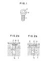
- Fig. 1 is a perspective view of a fixed contact of a magnet switch for a starter, in which a contact base member is formed of one metal which is soft iron of relatively low hardness in the form of a rod with a head and has intimately attached to its head la a contact member 2 which is formed of a good conductor metal, such as copper.
- the fixed contact of the aforesaid construction is produced as follows. As shown in Fig. 2-a, a cylindrical blind hole lb of about 6 mm in diameter and about 3 mm in depth is formed in the contact base member 1 to extend from the upper surface of its head la inwardly thereof, and then the contact base member 1 is placed on a lower die I in such a manner that the underside of the head la is in contact with the upper surface of the lower die I, so that the contact base member 1 is positioned with a rod-shaped portion lc thereof of about 7 mm in diameter and about 24 mm in height being held in position between lower dies I and I A .
- the head la is about 9 mm in diameter and about 6.5 mm in height.
- the contact member 2 of about 3.3 to 3.4 mm in height and substantially the same volume as the blind hole lb is inserted in the latter with a clearance of less than about 0.2 mm between the inner wall surface of the hole lb and the outer periphery of the contact member 2.
- the contact member 2 projects outwardly of the surface of the head la by about 0.3 to 0.4 mm.
- An upper die II shown in Fig. 2-a is gradually moved downwardly, to first cause the blind hole lb to be filled with the contact member and then to compress the head la as shown in Fig. 2-b as the upper die II is further moved downwardly.
- both the two member 1 and 2 expand radially and undergo plastic deformation in such a manner that the contact member 2 is enveloped by the contact base member 1, whereby, the contact base member 1 is shaped into a trapezoidal form of substantially the same height and the surface of the contact member 2 and the surface of the contact base member 1 adjacent each other are flush with each other.
- Fig. 3-a shows-in section the metal of the contact member (copper) 2 inserted in the blind hole lb formed at one end of the contact base member (soft iron) 1.
- the section is graduated to shown the condition of deformation caused by the flow of the metals.
- the compressive force exerted on the contact member 2 tends to expand the blind hole lb of the contact base member 1 and the compressive force exerted on the contact base member 1 tends to compress the contact member 2 in the blind hole lb, so that stresses jostling each other are produced at the boundary between the two metals 1 and 2.
- no gap is formed between the two members 1 and 2 which undergo plastic deformation and flow smoothly as if they were integral, so that the two members are joined together with the stresses being uniformly distributed in the contact interface between them.
- the contact member is deformed to achieve the integration.
- pressure is applied to both the contact base member and the contact member to compress same to cause them to undergo plastic deformation, so that the two metals behave as if they were a fluid when they are subjected to plastic deformation.
- the compression and flattening ratios can be about 0.6 and 0.5 respectively.
- the two members 1 and 2 were subjected to plastic compression by meeting the aforesaid requirements, they showed an increase in the area of contact of about 10% and the angle of inclination a of the axial interface between the contact base member and the contact member with respect to the axis was about 16 degrees.
- the blind hole lb has a flat bottom.
- the bottom substantially in the form of a bowl, it is possible to increase the area of contact interface between the two members 1 and 2, to thereby increase the density per unit area of the current in the center of the bottom of the contact member 2 which is united with high joint strength to the contact base member 1.
- the contact obtained optimally suits the condition of use.
- the blind hole lb formed in the contact base member 1 has been shown and described as being cylindrical in shape. However, it is to be understood that the invention is not limited to this specific form of the blind hole lb and that a polygonal shape may be selected for the blind hole lb in a case where turning moment is applied to the contact. The shape of the blind hole lb had better be selected depending on the use to which the contact is put.
- FIGs. 6-a, 6-b and 6-c show another embodiment of the invention for producing an electric contact.
- a contact base member 11 includes a head lla formed t one end with a blind hole llb of substantially the same dimentions as the blind hole llb of the first embodiment but having a bottom of the bowl shape having fitted therein with a contact member 12 of a height of about 6.5 mm having a volume larger than the volume of the blind hole llb.
- a lower die III is of the same shape as that described by referring to the first embodiment, but an upper die IV is formed at a pressing surface VI thereof with a recess V of a volume equal to the volume of the excess material of the contact member 12 which equals to a value subtracting the volume of the hole llb from the volume of the contact member 12.
- the two members 11 and 12 When the two members 11 and 12 are compressed and their metals undergo plastic deformation with the same compression ratio and flattening ratio as those described with reference to the first embodiment, they are brought to intimate contact with and united to each other on the same principles described by referring to the first embodiment.
- the excess material of the contact member 12 fills the recess V of the upper die IV.
- an upper die VII having a planar pressing surface as shown in Fig. 6-c
- the excess material thereof is extended on the surface of the head of the contact base member, to thereby provide a large surface area of contact member.
- the contact produced by the method of this embodiment in conformity with the invention not only has high joint strength between the two members of dissimilar metals but also has a large surface area at the surface of the contact member 12, so that it suits the condition of use.
Landscapes
- Engineering & Computer Science (AREA)
- Mechanical Engineering (AREA)
- Manufacturing & Machinery (AREA)
- Manufacture Of Switches (AREA)
- Forging (AREA)
- Contacts (AREA)
Applications Claiming Priority (2)
| Application Number | Priority Date | Filing Date | Title |
|---|---|---|---|
| JP56029906A JPS5942580B2 (ja) | 1981-03-04 | 1981-03-04 | 電気接点の製造方法 |
| JP29906/81 | 1981-03-04 |
Publications (2)
| Publication Number | Publication Date |
|---|---|
| EP0059341A1 true EP0059341A1 (de) | 1982-09-08 |
| EP0059341B1 EP0059341B1 (de) | 1985-10-23 |
Family
ID=12289021
Family Applications (1)
| Application Number | Title | Priority Date | Filing Date |
|---|---|---|---|
| EP82100930A Expired EP0059341B1 (de) | 1981-03-04 | 1982-02-09 | Verfahren zur Herstellung elektrischer Kontakte |
Country Status (4)
| Country | Link |
|---|---|
| US (1) | US4821412A (de) |
| EP (1) | EP0059341B1 (de) |
| JP (1) | JPS5942580B2 (de) |
| DE (1) | DE3266973D1 (de) |
Cited By (6)
| Publication number | Priority date | Publication date | Assignee | Title |
|---|---|---|---|---|
| US4821412A (en) * | 1981-03-04 | 1989-04-18 | Hitachi, Ltd. | Method of producting an electric contact |
| FR2627894A1 (fr) * | 1988-02-25 | 1989-09-01 | Merlin Gerin | Contact electrique a pastille de contact frittee et son procede de fabrication |
| US4910868A (en) * | 1988-02-25 | 1990-03-27 | Merlin Gerin | Manufacturing process of an electrical contact with contact pad |
| EP0974991A1 (de) * | 1998-07-21 | 2000-01-26 | STA. FIL SpA | Verfahren zur Herstellung von Bimetallkontakten für elektromagnetische Einheiten für Anlassmotoren |
| CN100495608C (zh) * | 2006-06-20 | 2009-06-03 | 杭州之江开关股份有限公司 | 断路器动触头辫子线冷挤压工艺 |
| CN101707151B (zh) * | 2009-11-30 | 2011-10-05 | 李建民 | 断路器触头辫子线冷挤压工艺 |
Families Citing this family (10)
| Publication number | Priority date | Publication date | Assignee | Title |
|---|---|---|---|---|
| JPH01248413A (ja) * | 1988-03-30 | 1989-10-04 | Tanaka Kikinzoku Kogyo Kk | モールド挿入型電気接点の製造方法 |
| JPH02239526A (ja) * | 1989-03-10 | 1990-09-21 | Tanaka Kikinzoku Kogyo Kk | モールド装入型電気接点の製造方法 |
| US5020217A (en) * | 1990-02-06 | 1991-06-04 | General Electric Company | Methods for fabricating an electrical contact |
| DE29718270U1 (de) * | 1997-10-15 | 1997-12-11 | Hentschel, Holger, Dipl.-Ing., 27751 Delmenhorst | Kontaktelement für stromführende Teile, insbesondere Schalter |
| KR20050052868A (ko) * | 2003-12-01 | 2005-06-07 | 희성금속 주식회사 | 전기접점 가공방법 |
| US20050150097A1 (en) * | 2004-01-09 | 2005-07-14 | Jones Ronald E. | Cold process for joining metal |
| EP1895621A1 (de) * | 2006-09-02 | 2008-03-05 | ABB Technology AG | Elektrische Kontaktanordnung, insbesondere für Mittelspannungsanlagen, sowie Verfahren zur Herstellung derselben |
| FR2916582B1 (fr) * | 2007-05-24 | 2009-12-11 | Vis Samar | Vis,notamment borne electrique de demarreur,et procede de realisation |
| MC200158B1 (fr) | 2013-06-11 | 2014-07-09 | Dinegro Stefano | Vis pour contacts électriques |
| WO2017168851A1 (ja) * | 2016-04-01 | 2017-10-05 | ウチヤ・サーモスタット株式会社 | 電気接点の製造方法 |
Citations (5)
| Publication number | Priority date | Publication date | Assignee | Title |
|---|---|---|---|---|
| DE567125C (de) * | 1931-05-06 | 1933-01-03 | Schunk & Ebe | An einem Traeger befestigtes, aus Kohle bestehendes elektrisches Kontaktstueck |
| GB591183A (en) * | 1944-01-08 | 1947-08-11 | Rene Pointout | Improvements in electric contacts |
| US2715169A (en) * | 1950-07-21 | 1955-08-09 | Honeywell Regulator Co | Switch contact |
| GB1132520A (en) * | 1965-11-02 | 1968-11-06 | Mallory Metallurg Prod Ltd | Improvements in or relating to composite electrical contacts |
| FR2030941A5 (de) * | 1969-01-28 | 1970-11-13 | Bosch |
Family Cites Families (8)
| Publication number | Priority date | Publication date | Assignee | Title |
|---|---|---|---|---|
| US2646613A (en) * | 1946-09-12 | 1953-07-28 | Honeywell Regulator Co | Method of making switch contacts |
| DE1208498B (de) * | 1958-04-09 | 1966-01-05 | Siemens Ag | Verfahren zur Herstellung eines Sinterwerkstoffes fuer elektrische Kontakte |
| US3547334A (en) * | 1967-05-25 | 1970-12-15 | Contacts Inc | Apparatus for making cold bonded electrical composite contacts |
| US3686457A (en) * | 1971-02-04 | 1972-08-22 | Texas Instruments Inc | Improved electrical contact having a heat sink layer |
| DE2555697B2 (de) * | 1975-12-11 | 1978-08-03 | Dr. Eugen Duerrwaechter Doduco, 7530 Pforzheim | Verfahren zum Herstellen von Doppelkontaktnieten |
| SU642779A1 (ru) * | 1976-08-02 | 1979-01-15 | Научно-исследовательский и экспериментальный институт автомобильного электрооборудования и автоприборов | Электрический контакт |
| JPS54150678A (en) * | 1978-05-19 | 1979-11-27 | Tetsuo Takano | Square electric contact |
| JPS5942580B2 (ja) * | 1981-03-04 | 1984-10-16 | 株式会社日立製作所 | 電気接点の製造方法 |
-
1981
- 1981-03-04 JP JP56029906A patent/JPS5942580B2/ja not_active Expired
-
1982
- 1982-02-09 DE DE8282100930T patent/DE3266973D1/de not_active Expired
- 1982-02-09 EP EP82100930A patent/EP0059341B1/de not_active Expired
-
1985
- 1985-06-28 US US06/749,763 patent/US4821412A/en not_active Expired - Fee Related
Patent Citations (5)
| Publication number | Priority date | Publication date | Assignee | Title |
|---|---|---|---|---|
| DE567125C (de) * | 1931-05-06 | 1933-01-03 | Schunk & Ebe | An einem Traeger befestigtes, aus Kohle bestehendes elektrisches Kontaktstueck |
| GB591183A (en) * | 1944-01-08 | 1947-08-11 | Rene Pointout | Improvements in electric contacts |
| US2715169A (en) * | 1950-07-21 | 1955-08-09 | Honeywell Regulator Co | Switch contact |
| GB1132520A (en) * | 1965-11-02 | 1968-11-06 | Mallory Metallurg Prod Ltd | Improvements in or relating to composite electrical contacts |
| FR2030941A5 (de) * | 1969-01-28 | 1970-11-13 | Bosch |
Cited By (6)
| Publication number | Priority date | Publication date | Assignee | Title |
|---|---|---|---|---|
| US4821412A (en) * | 1981-03-04 | 1989-04-18 | Hitachi, Ltd. | Method of producting an electric contact |
| FR2627894A1 (fr) * | 1988-02-25 | 1989-09-01 | Merlin Gerin | Contact electrique a pastille de contact frittee et son procede de fabrication |
| US4910868A (en) * | 1988-02-25 | 1990-03-27 | Merlin Gerin | Manufacturing process of an electrical contact with contact pad |
| EP0974991A1 (de) * | 1998-07-21 | 2000-01-26 | STA. FIL SpA | Verfahren zur Herstellung von Bimetallkontakten für elektromagnetische Einheiten für Anlassmotoren |
| CN100495608C (zh) * | 2006-06-20 | 2009-06-03 | 杭州之江开关股份有限公司 | 断路器动触头辫子线冷挤压工艺 |
| CN101707151B (zh) * | 2009-11-30 | 2011-10-05 | 李建民 | 断路器触头辫子线冷挤压工艺 |
Also Published As
| Publication number | Publication date |
|---|---|
| JPS57146442A (en) | 1982-09-09 |
| EP0059341B1 (de) | 1985-10-23 |
| DE3266973D1 (en) | 1985-11-28 |
| US4821412A (en) | 1989-04-18 |
| JPS5942580B2 (ja) | 1984-10-16 |
Similar Documents
| Publication | Publication Date | Title |
|---|---|---|
| US4821412A (en) | Method of producting an electric contact | |
| EP0086036B1 (de) | Verfahren und Vorrichtung zur Formung eines zylindrischen Stückes, insbesondere eines elektrischen Verbindungsgliedes | |
| US5508488A (en) | Method of projection-welding bolts | |
| US5499449A (en) | Method of manufacturing battery terminals | |
| US3952390A (en) | Method of producing ball joints | |
| US2755368A (en) | Welding method | |
| JP2026012532A (ja) | 固着具と固着具の固定方法 | |
| US4263799A (en) | Method and machine for forming a lump on the end of a pipe | |
| JPH1035235A (ja) | サスペンションアーム材 | |
| US3341943A (en) | Method of making electrical contact elements | |
| JP3517559B2 (ja) | コイニングによる抵抗溶接用リング溝の成形方法 | |
| GB2169527A (en) | Method for producing an electrode for spark plug | |
| US3277559A (en) | Method of cold pressure welding | |
| JPH09236105A (ja) | 複合金属板および金属板の接合方法とその接合装置 | |
| US4151392A (en) | Method of manufacturing electrical connector | |
| JP4532769B2 (ja) | 電気融着継手の製造方法 | |
| CA1178243A (en) | Process for manufacturing plastically deformed light metal objects and shaped bodies having a light metal part | |
| US1999784A (en) | Uniting parts | |
| JP2025181408A (ja) | 二次電池の端子および二次電池の端子の製造方法 | |
| JPH1177192A (ja) | アルミ合金鋳物の通電カシメ方法 | |
| GB2103974A (en) | An electric upsetting device | |
| JPH06226466A (ja) | 点溶接機の電極チップ用チップ部材とその製造方法 | |
| JPH0532888B2 (de) | ||
| US2734121A (en) | dicome | |
| JP2026077305A (ja) | 二次電池の端子 |
Legal Events
| Date | Code | Title | Description |
|---|---|---|---|
| PUAI | Public reference made under article 153(3) epc to a published international application that has entered the european phase |
Free format text: ORIGINAL CODE: 0009012 |
|
| AK | Designated contracting states |
Designated state(s): DE GB |
|
| 17P | Request for examination filed |
Effective date: 19830128 |
|
| R17P | Request for examination filed (corrected) |
Effective date: 19830128 |
|
| GRAA | (expected) grant |
Free format text: ORIGINAL CODE: 0009210 |
|
| AK | Designated contracting states |
Designated state(s): DE GB |
|
| REF | Corresponds to: |
Ref document number: 3266973 Country of ref document: DE Date of ref document: 19851128 |
|
| PLBE | No opposition filed within time limit |
Free format text: ORIGINAL CODE: 0009261 |
|
| STAA | Information on the status of an ep patent application or granted ep patent |
Free format text: STATUS: NO OPPOSITION FILED WITHIN TIME LIMIT |
|
| 26N | No opposition filed | ||
| GBPC | Gb: european patent ceased through non-payment of renewal fee |
Effective date: 19960209 |
|
| PGFP | Annual fee paid to national office [announced via postgrant information from national office to epo] |
Ref country code: GB Payment date: 19970102 Year of fee payment: 16 |
|
| GBPC | Gb: european patent ceased through non-payment of renewal fee |
Free format text: DELETE IN JOURNAL 5607, PAGE 4902 CEASED IN ERROR |
|
| PGFP | Annual fee paid to national office [announced via postgrant information from national office to epo] |
Ref country code: DE Payment date: 19970327 Year of fee payment: 16 |
|
| PG25 | Lapsed in a contracting state [announced via postgrant information from national office to epo] |
Ref country code: GB Effective date: 19980209 |
|
| GBPC | Gb: european patent ceased through non-payment of renewal fee |
Effective date: 19980209 |
|
| PG25 | Lapsed in a contracting state [announced via postgrant information from national office to epo] |
Ref country code: DE Free format text: LAPSE BECAUSE OF NON-PAYMENT OF DUE FEES Effective date: 19981103 |