EP0059972A1 - Plate-forme de montage pour le soutènement de galeries d'exploitation au fond - Google Patents
Plate-forme de montage pour le soutènement de galeries d'exploitation au fond Download PDFInfo
- Publication number
- EP0059972A1 EP0059972A1 EP82101840A EP82101840A EP0059972A1 EP 0059972 A1 EP0059972 A1 EP 0059972A1 EP 82101840 A EP82101840 A EP 82101840A EP 82101840 A EP82101840 A EP 82101840A EP 0059972 A1 EP0059972 A1 EP 0059972A1
- Authority
- EP
- European Patent Office
- Prior art keywords
- elements
- platform
- removal assembly
- floor plan
- edges
- Prior art date
- Legal status (The legal status is an assumption and is not a legal conclusion. Google has not performed a legal analysis and makes no representation as to the accuracy of the status listed.)
- Granted
Links
- 238000005065 mining Methods 0.000 title abstract 2
- 239000000725 suspension Substances 0.000 claims abstract description 11
- 230000005540 biological transmission Effects 0.000 claims description 3
- 239000002131 composite material Substances 0.000 claims description 3
- 230000001154 acute effect Effects 0.000 claims description 2
- 241001125292 Balaena mysticetus Species 0.000 claims 1
- 230000003245 working effect Effects 0.000 abstract 1
- 229910052751 metal Inorganic materials 0.000 description 9
- 239000002184 metal Substances 0.000 description 8
- 238000005452 bending Methods 0.000 description 5
- 238000010276 construction Methods 0.000 description 5
- 238000010586 diagram Methods 0.000 description 3
- XEEYBQQBJWHFJM-UHFFFAOYSA-N Iron Chemical compound [Fe] XEEYBQQBJWHFJM-UHFFFAOYSA-N 0.000 description 2
- 230000004308 accommodation Effects 0.000 description 2
- 230000000712 assembly Effects 0.000 description 1
- 238000000429 assembly Methods 0.000 description 1
- 230000015572 biosynthetic process Effects 0.000 description 1
- 239000000969 carrier Substances 0.000 description 1
- 239000003245 coal Substances 0.000 description 1
- 238000005553 drilling Methods 0.000 description 1
- 230000002349 favourable effect Effects 0.000 description 1
- 229910052742 iron Inorganic materials 0.000 description 1
- 238000004904 shortening Methods 0.000 description 1
- 239000004575 stone Substances 0.000 description 1
- 238000003466 welding Methods 0.000 description 1
Images




Classifications
-
- E—FIXED CONSTRUCTIONS
- E21—EARTH OR ROCK DRILLING; MINING
- E21D—SHAFTS; TUNNELS; GALLERIES; LARGE UNDERGROUND CHAMBERS
- E21D11/00—Lining tunnels, galleries or other underground cavities, e.g. large underground chambers; Linings therefor; Making such linings in situ, e.g. by assembling
- E21D11/40—Devices or apparatus specially adapted for handling or placing units of linings or supporting units for tunnels or galleries
Definitions
- the invention relates to a removal assembly platform for lines of underground operations according to the preamble of claim l.
- the working platform of such platforms can generally be moved on a track laid in the top of the line with the help of trolleys. In addition, the platform can be raised and lowered opposite the track.
- the designated connection consoles of the work platform are used to connect the trolleys and / or the hoists with which these functions are carried out.
- the floor plan of the work platform is usually longer in its longitudinal dimension than transverse to it, the trolleys are usually attached so that the front part of the stage with a predetermined length in the undeveloped in the track location Section part can be moved.
- a manipulator usually interacts with this front part of the stage, mainly for parts of the track extension, preferably for several ridge segments combined to form a canopy.
- the removal assembly platform can also have other devices, for example movable platform parts, which, in their effective position, make it possible to drill the track location, possibly also during the final assembly of the track extension.
- such extension platforms are used in the track location and at a remote location connected to it by the track.
- the removal components mentioned are preferably pre-assembled on this on the removal manipulator in the lowered position of the work platform. Then you lift the work platform with the help of the lifting equipment so that you can spend it in its on-site position across the various facilities of the route. There the stage is locked, so that the work platform forms a reliable abutment for the removal manipulator and other mechanical equipment of the stage, as well as a safe standing area for the workers involved in the assembly of the removal and possibly for the drilling equipment.
- such an extension assembly platform can also be provided with an extension which can be braced with the face, which prevents the stone and coal from falling there.
- Removal assembly platforms are known for the purposes described at the outset, which remove the reaction forces emanating from the connection brackets via two parallel I-section supports, on which the actual work platform is suspended in a height-adjustable manner (DE-PS 23 60 726). Such removal assembly platforms have a relatively complicated structure and a considerable overall weight.
- the invention is therefore based on another of the known removal assembly platforms (DE-PS 28 11 580), in which the stage supports and the surface of the work platform lie in one plane.
- that part of the work platform which is not formed by the upper side of the stage girders designed as hollow girders is composed of pontoon-like elements which are screwed partly to one another and partly to the hollow girders.
- the connection brackets are attached to the top of the supports, which relieve the elements of the reaction forces.
- the disadvantage of this stage construction is that the beams have to be connected to practically all elements in order to ensure sufficient strength of the work platform. This then results in relatively long beams in the longitudinal direction, the high weights of which can be reduced by the hollow beam formation and their poor transportability one tries to compensate by pluggable carrier sections.
- the invention is based on the object of reducing the necessary beam lengths and accordingly increasing the load-bearing capacity of the platform parts consisting of the elements fastened to one another.
- the edges of one another in at least one surface dimension of the work platform of adjacent elements are allowed to jump in the direction of this dimension, a joint offset is created which ensures a sufficient bending tensile strength of the element composite. Therefore, one can get by with short carrier lengths that only absorb the reaction forces of one or more connection brackets simultaneously and transmit and distribute them from below to the elements or plates or several elements.
- connection brackets After one assumes an essentially predetermined transverse spacing of the connection brackets, which should be as large as possible for reasons of stability and, on the other hand, wants to keep the transverse dimensions of the working platform as small as possible, among other things in order to be able to move the working platform as high as possible above the track base, the distance becomes Connection brackets from the longitudinal edges of the work platform increasingly less.
- the shortening of the carrier or their arrangement achievable according to the invention then allows the characteristics of the To realize claim 2 and thereby to dispense with a foldability of the elements that enlarge the work platform.
- the stability of the removal assembly platform usually requires four trolleys, which are arranged at the corners of a square or rectangle enclosed by the longitudinal and transverse edges of the platform and can be moved on two hanging rails of the track.
- the hoists carry the working platform on the connection brackets and enable the adjustment of the respective working height of the platform.
- the removal assembly platform is usually equipped with a removal manipulator, it can also be used to assemble a corresponding number of structures on site when the removal manipulator is set up to accommodate several ridge segments of the track extension at the same time. In the latter case, a cap screen is preassembled in a section of the route lying behind the route location with the work platform lowered, which is brought into the route location by the removal assembly platform in the raised state and there under the exposed roof is raised. Then the removal assembly platform is determined so that the canopy can first be used as a preliminary extension for securing and then for the final assembly of the relevant track construction.
- the extension platform is particularly heavily loaded and must therefore be secured against breakage of the traction devices of the hoists.
- the hoists must be adapted by their structure to the relative simplicity of the lifting operations with sufficient height adjustability of the working platform, but on the other hand, the structure of the hoists must also ensure a simple and safe design of the stage suspension, which is effective when the hoists are switched off.
- DBP 23 60 726 It is known (DBP 23 60 726) to use the lifting trolleys developed for underground transportation on monorail overhead conveyors as hoists and to connect their traction devices to a stage frame consisting of several supports, to which the work platform is attached in a height-adjustable manner with the aid of several hydraulic push piston gears.
- the stage frame In order to be able to reach a sufficient height of the work platform, the stage frame must be be lifted up to just below the roof. This forces a relatively complicated stage suspension. It consists of several support hooks that can be swiveled into the stage frame and a support roller arranged at the rear end, which rolls on a hanging rail. If one takes into account the large number of hoists, the overall structure is too complex.
- the invention is based on another of the previously known assembly platforms (DBP 28 11 580).
- the beams that form the stage frame are integrated into the work platform, and hollow beams that can be plugged together are also used, with which edges of sheet metal elements that can be screwed together are screwed in order to ensure the required bending tensile strength of the platform.
- the connection brackets are attached to the hollow girders and not only serve to connect the flexible traction means of the known lifting trolleys, with which the stage can be moved on the monorail rails forming the track and is adjustable in height relative to these.
- the connection brackets also take up the stage suspension.
- This consists of a telescopic tube arrangement assigned to each connection console, which is attached at one end to the trolley and can be connected to the relevant connection console by means of plug-in bolts when the work platform is raised.
- a telescopic tube arrangement assigned to each connection console, which is attached at one end to the trolley and can be connected to the relevant connection console by means of plug-in bolts when the work platform is raised.
- plug-in bolts When the work platform is raised.
- the telescopic tubes attached to the rear end prevent the work platform from tipping over because of their mutual positive locking and the positive locking with the trolleys and connection brackets.
- the invention aims to simplify the hoists in such a way that the lifting trolleys previously required can be dispensed with and the drives of the traction means must be arranged in such a way that the connection brackets for the connection of the known stage suspension or a similarly practical suspension also remain usable.
- the drives can be realized with single or double-acting, single or multiple thrust piston drives on the one hand and both ends of the just set the articulated traction device to the relevant connection console, which means that simple trolleys are used and connection consoles are kept to which the stage suspension can be connected.
- the length of the elements in which the thrust piston gears are accommodated generally does not depend on the extended length of the thrust piston gears, but on various other aspects.
- the implementation of the invention with the features of claim 12 is expedient, because then the accommodation of the traction drive is possible with a stroke that exceeds the available length within the elements.
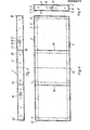
- FIG. 3 to 5 consists of a work platform elements 1 made of sheet metal 2, which is a strength part 3 of the surface in detail from the F. l and 2 recognizable work platform.
- the sheet has double-folded longitudinal edges 4 and 5; 6 and 7. This results in the C-shaped cross section shown in FIG. 5, the downward-pointing legs 12 and 14 of which, as shown in FIG. 3, are provided with cutouts 15 and 16, respectively.
- the longer axis 17 of these congruent recesses 15 and 16 runs in the direction of the longitudinal edges 4 and 5; 6 or 7, while the shorter axis 18 is perpendicular thereto.
- the edges of the sheet carry 2 angle profiles legs 8, 9 and 10, 11, which are perpendicular to each other 16 corresponds and therefore allows the screwing of the element on the narrow sides with other elements.
- the sheet 2 is stiffened because of its relatively large extension in the longitudinal direction of angle profile sections 24, 25, which are at a distance from the transverse edges 19, 20 and at a mutual distance from cross each other and are attached so that one leg 27 perpendicular to the sheet 2 and the other leg 28 parallel to the folds 5, 7.
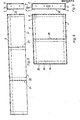
- the element 30 shown in FIGS. 6 and 7 corresponds to one half of the element 1 divided in its longitudinal center and is therefore provided with corresponding reference numerals. Since it lacks bends or angular profiles on its longitudinal edge 31 corresponding to the dividing line, it can be oriented outwards with this longitudinal edge 31 and form an outer element of the work platform.
- the remaining parts of element 32 correspond to the relevant parts in element 1.
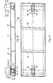
- connection brackets 38, 39 are attached to this element.
- These connection brackets are generally U-shaped.
- the web 40 of the profile lies with its outer side 40 ′ on the upper side 41 of the sheet 2. It carries several bores 42 for a hexagon head screw 43 and 44, respectively. These screws hold, with their nuts 45, 46, a flat iron bracket 47 under a hollow profile carrier 49, which on the underside 50 of the Sheet 2 is welded.
- the two flanges 51 and 52 of the brackets in turn carry holes 53, 54 for the connection of hoists, support chains, support hooks or the like. These devices are not shown.
- the two hollow beams 49 and 55 can be connected in the manner shown in FIG. 10 with only one bracket 38, 39 but also with a plurality of brackets, preferably arranged next to one another in the transverse direction.
- the element 36 with two brackets 38, 39 arranged on its transverse edges can also be provided with only one bracket of this type, which is then expediently located in the middle between the angle profile sections 24 and 25 in the embodiment shown in FIG 10 obvious manner is attached.
- the element 56 according to FIGS. 12 to 14 can correspond to element 32, but also to element 1.
- the illustration assumes that element 1 is involved, so that FIG. 12 corresponds to FIG. 5.
- the reference numerals of FIG. 5 are entered accordingly in FIG. 12.
- the angular profile of the transverse edge 20 with the legs 10 and 11 has been omitted, so that the outer edge 57 corresponding to the transverse edge is free.
- a hollow support 58 is supported, which partially closes the side 57 below. It serves to guide the side members 59, 60 of a frame 61, the frame members 63, 64 of which are perpendicular to this can be seen in the illustration in FIG. 13.
- This frame 61 supports a sheet metal 66, which has the surface of a drawer-shaped side element 67 forms.
- the frame member arranged on the outside carries two profile sections 69, 70 which run perpendicular to the sheet metal 66 and with which the drawer-like side element 67 can be handled.
- the basic elements of a modular system, from which work platforms can be assembled consist of at least two types of elements 1 and 32 having the same floor plan, of which two elements 32 of the one connected to each other at their adjacent transverse edges 34 kind together give the floor plan of an element 1 of the other type.
- This kit can be expanded by elements of a third type, which make up half of an element 1, which can be assembled from two elements 32 of a different type; this element can be provided with a free edge 31.
- the kit can have elements of one and the other type 1, 32, which are provided with the drawer-shaped element 67.
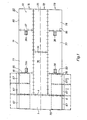
- FIG. 1 An embodiment of a work platform resulting from such a modular system is shown in FIG. 1.
- the platform front side 70 is formed here by an element 1, which is provided on its two transverse edges 4 and 6 with a drawer-shaped element 67 and determines the transverse dimensions of the platform with its length. It is attached to the platform section 71 with one of its longitudinal edges 4.
- This platform section basically consists of a middle section 72 and a side section 73, 74 each. These parts of the platform section 71 are congruent, but made of different elements of the modular system.
- the center piece 72 is composed of an element 75 or 76 of the first type shown at 1 in FIGS. 2 to 5.
- the two side parts 73 and 74 are made up to match and consist of an element 77 or 78 of the first type shown in FIG. 1 and two other transverse edges connected elements 78, 79 or 80, 81 of the second type shown in 32 arranged in the middle
- the side elements 79 and 81 adjoining the front part 70, each with two drawer-shaped elements 67 . provided on the outside.
- One of the two hollow supports (not shown) connects the fastenings of the brackets 39, 39a and 38, 38a arranged next to one another in the transverse direction.
- the embodiment of FIG. 2 differs from the embodiment of FIG. 1 in that the platform section 71 are composed differently.
- the platform side parts 73, 74 are composed like the center piece 72 according to FIG. 1, while the center piece 72 of the embodiment according to FIG. 2 is composed like one of the side parts 73, 74 according to FIG. 1, which is indicated by corresponding reference numerals.
- an element of the type designated 30 is attached to the element of the type designated 1, namely to its front transverse edge 5.
- the hollow beams 49, 55 which are also not shown in the embodiment in FIG. 2, run in the longitudinal direction in this exemplary embodiment, thus under the elements 75 and 76 of the side parts 73, 74.
- the arrangement of the elements is now such that in the work platform, generally designated 90, the surface 91 of which is formed exclusively from the mutually aligned metal sheets 2 of fixed elements 1, 32 and 30; the transverse to the longer, i.e. In the longitudinal dimension of the surface 91 adjacent elements are arranged in their majority with their edges extending in this direction in the other surface dimension.
- the elements 79, 76 are adjacent to one another transversely to the longer dimension. At least the edges 93, 94 of these elements jump in the longitudinal direction. This also applies to the transverse edge 94 of the element 76 in relation to the transverse edge 95 of the adjacent element 79. Furthermore, this also applies to the transverse edges 96, 97 of the elements 77 in relation to the respectively adjacent element 76 and 75.
- the drawer-shaped element 67 is made of a plate forming the upper side, ie a plate 2, which corresponds to the element plate 2, which has side parts 98, 99 projecting beyond the frame members, which are guided on angle profiles 100 and 100 '.
- the transverse edges of the elements connected to one another are offset. This increases the bending tensile strength of the platform, especially in the longitudinal direction of the route.
- the carriers 49, 55 are also square tubes. If these tubes are arranged in the transverse direction of the elements, they can interact with a hole program for the bow bolts 43 and 44, which enables the brackets to be adjusted transversely. As a result, the track of the track consisting of two rails can be varied for the at least four trolleys and adapted accordingly to the track width.
- the supports can also be used as stiffening elements of the plates or sheets 2 or, conversely, stiffening elements as supports.
- the element 1 arranged on the platform front side 70 can be replaced by an element of the type of elements 79, 81 if each element 79, 81 is replaced by an element 1 in which then the drawers are attached to the side.
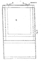
- the work platform or the removal assembly platform is only partially, i.e. reproduced with only one of its elements, designated 101.
- This element consists of a plate 103 which forms the upper side of the relevant part of the work platform and which is formed by a plate with a rectangular plan.
- the longer edges 104 and 105 and the shorter edges 106 and 107 of the sheet metal, which are at right angles thereto, are folded twice so that vertical walls 107 'and adjoining extensions 108 lying in a plane parallel to the sheet metal are bent on all four edges 104- 107 result.
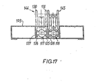
- the longitudinal and cross-section then results in the C-shape of the element shown in FIGS. 15 and 17, which thereby obtains a high degree of inherent rigidity.
- the work platform can be assembled from a plurality of such elements according to a predetermined grid, the surfaces 102 of the elements being aligned and the elements being fastened to one another with their walls 107 ', e.g. are screwed.
- Such a work platform which is built according to a certain grid, is usually hung in at least four places. 15, however, only two of these suspensions are shown, namely on a hanging rail 109 laid in the roof of a section, which forms a track with a further hanging rail laid in parallel.
- the trolleys are of a known construction and are therefore not reproduced in their details, but only indicated with their side shields.
- a traction mechanism drive 117 or 118 is fitted with the aid of a roller 119, which is mounted in the forked head 120 of a piston rod 121, which in turn is guided in a hollow piston rod 122.
- the piston of the piston rod 122 runs in the cylinder 123, which carries a hinge pin 124 at its end.
- the hinge pin sits in a bushing, the jaws 125, 126 of which are welded to gusset plates 127, 128.
- the gusset plates 127, 128 are welded into the C-shaped space, which is enclosed by the parts 103, 107 'and 108.
- the parts 121-123 form a hydraulically actuated, single or double-acting thrust piston gear, which serves to drive the traction means 114.
- the traction means 114 is deflected with a roller 129, which is mounted in the two end shields 130, 131 of a connection bracket 132, which is assigned to the traction mechanism 114 and its thrust piston gear according to the illustrated embodiment.
- the two end shields are stiffened with the help of connecting gusset plates 134, 135 and, moreover, have aligned bores 136 for plug bolts. This makes it possible to formally connect the consoles 132 to the telescopic tube arrangements mentioned at the outset, for example to the aligned bores indicated at 137 can be connected in the end shields of the trolley 110.
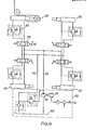
- Fig. 18 shows a hydraulic circuit diagram.
- the parts surrounded by dash-dotted lines 150 are in a known hydraulic drive station, which can be accommodated on the work platform itself and e.g. has a compressed air drive 151 for the hydraulic pump 152, which takes the hydraulic working medium from the tank 153 and brings it to the required operating pressure.
- a feed line 154 extends from this drive station 150, the return flow of the working medium taking place through line 155.
- the total of four with hydraulic thrust piston gears The work platform equipped in connection with FIG. 15 can be raised and lowered with the traction mechanism drive designated 156-159 in the circuit diagram of FIG. 18.
- the traction mechanism drive designated 156-159 in the circuit diagram of FIG. 18.
- each assigned to one of the actuators 156-159 which, as indicated at 161 can be adjusted by hand, it is possible to actuate each actuator 156-159 for itself, so that the working platform is on their four suspension points can be adjusted.
- Each of the double-acting thrust piston gears forming the drives 156-159 is also secured with a lowering brake valve arrangement 162.
- This is a pipe rupture protection provided with non-return valves and an overpressure protection which ensures that the excess pressure is released into line 155 in good time if the operating pressure is exceeded.
Landscapes
- Engineering & Computer Science (AREA)
- Mining & Mineral Resources (AREA)
- Architecture (AREA)
- Civil Engineering (AREA)
- Structural Engineering (AREA)
- Life Sciences & Earth Sciences (AREA)
- General Life Sciences & Earth Sciences (AREA)
- Geochemistry & Mineralogy (AREA)
- Geology (AREA)
- Forklifts And Lifting Vehicles (AREA)
Applications Claiming Priority (4)
| Application Number | Priority Date | Filing Date | Title |
|---|---|---|---|
| DE19813109159 DE3109159A1 (de) | 1981-03-11 | 1981-03-11 | Ausbaumontagebuehne fuer strecken des untertagebetriebes |
| DE19813109163 DE3109163A1 (de) | 1981-03-11 | 1981-03-11 | Ausbaumontagebuehne fuer strecken des untertagebetriebes |
| DE3109163 | 1981-03-11 | ||
| DE3109159 | 1981-03-11 |
Publications (2)
| Publication Number | Publication Date |
|---|---|
| EP0059972A1 true EP0059972A1 (fr) | 1982-09-15 |
| EP0059972B1 EP0059972B1 (fr) | 1985-07-17 |
Family
ID=25791708
Family Applications (1)
| Application Number | Title | Priority Date | Filing Date |
|---|---|---|---|
| EP82101840A Expired EP0059972B1 (fr) | 1981-03-11 | 1982-03-09 | Plate-forme de montage pour le soutènement de galeries d'exploitation au fond |
Country Status (2)
| Country | Link |
|---|---|
| EP (1) | EP0059972B1 (fr) |
| DE (1) | DE3264719D1 (fr) |
Cited By (1)
| Publication number | Priority date | Publication date | Assignee | Title |
|---|---|---|---|---|
| CN114278367A (zh) * | 2021-12-20 | 2022-04-05 | 中国矿业大学 | 一种液压单元支架的搬运装置及其控制方法 |
Citations (1)
| Publication number | Priority date | Publication date | Assignee | Title |
|---|---|---|---|---|
| DE8024221U1 (de) * | 1980-09-11 | 1981-01-29 | Kbi Kloeckner-Becorit Industrietechnik Gmbh, 4224 Huenxe | Mehrzweckbuehne mit innenliegenden hebezeugen |
-
1982
- 1982-03-09 DE DE8282101840T patent/DE3264719D1/de not_active Expired
- 1982-03-09 EP EP82101840A patent/EP0059972B1/fr not_active Expired
Patent Citations (1)
| Publication number | Priority date | Publication date | Assignee | Title |
|---|---|---|---|---|
| DE8024221U1 (de) * | 1980-09-11 | 1981-01-29 | Kbi Kloeckner-Becorit Industrietechnik Gmbh, 4224 Huenxe | Mehrzweckbuehne mit innenliegenden hebezeugen |
Cited By (2)
| Publication number | Priority date | Publication date | Assignee | Title |
|---|---|---|---|---|
| CN114278367A (zh) * | 2021-12-20 | 2022-04-05 | 中国矿业大学 | 一种液压单元支架的搬运装置及其控制方法 |
| CN114278367B (zh) * | 2021-12-20 | 2024-02-23 | 中国矿业大学 | 一种液压单元支架的搬运装置及其控制方法 |
Also Published As
| Publication number | Publication date |
|---|---|
| DE3264719D1 (en) | 1985-08-22 |
| EP0059972B1 (fr) | 1985-07-17 |
Similar Documents
| Publication | Publication Date | Title |
|---|---|---|
| LU86532A1 (de) | Teleskopsaeule | |
| EP0727385A2 (fr) | Grue mobile sur rails | |
| EP0523757A2 (fr) | Pont déplaçable | |
| EP2643259A1 (fr) | Grue dotée d'une flèche de grue, en particulier grue à console | |
| EP0177895A2 (fr) | Obstacle antichar | |
| DE3303848C2 (fr) | ||
| DE3238945A1 (de) | Vorrichtung zum setzen von schneestangen oder dgl. | |
| EP0706969B1 (fr) | Ascenseur avec cabine montée en sac-à-dos sur un châssis | |
| DE20219299U1 (de) | Unterwagen eines Krans | |
| EP0059972B1 (fr) | Plate-forme de montage pour le soutènement de galeries d'exploitation au fond | |
| DE2450003C2 (de) | Fahrzeugkran mit Kabine mit verschiedenen Stellungen | |
| DE3307261A1 (de) | Lasthandhabungsgeraet | |
| DE19826560B4 (de) | Vorrichtung zur Überprüfung des Inhalts geschlossener Ladungsträger, insbesondere Container, unter Verwendung von Röntgenstrahlen | |
| EP0389781A1 (fr) | Châssis de levage | |
| DE20016624U1 (de) | Scherenhubtisch | |
| DE3109159A1 (de) | Ausbaumontagebuehne fuer strecken des untertagebetriebes | |
| DE19919702C1 (de) | Weiche | |
| DE2811580C3 (fr) | ||
| EP0073848B1 (fr) | Disposition de poulies pour un chemin de fer monorail suspendu entraîné par câble | |
| DE2840588C2 (de) | Schwerlastgehänge zum Heben, Senken und Transportieren sperriger und schwerer Lasten an Profilschienen, insbesondere an einer Fahrschiene von Einschienenhängebahnen im untertägigen Grubenbetrieb | |
| DE3826908C2 (fr) | ||
| DE19728822A1 (de) | Anbaunachlauffahrwerk | |
| DE3420829A1 (de) | System zum auswechseln von walzgeruesten eines formstahl-walzwerks, als walzgeruesttraeger dienender mehrfachfunktions-laufwagen fuer das aufstellen an den walzplaetzen und den transport zu den vormontagestellen | |
| DE3438775C1 (de) | Vorrichtung zum Überführen von Strebausbaugestellen | |
| DE8106857U1 (de) | Ausbaumontagebuehne fuer strecken des untertagebetriebes |
Legal Events
| Date | Code | Title | Description |
|---|---|---|---|
| PUAI | Public reference made under article 153(3) epc to a published international application that has entered the european phase |
Free format text: ORIGINAL CODE: 0009012 |
|
| AK | Designated contracting states |
Designated state(s): BE DE FR GB IT |
|
| 17P | Request for examination filed |
Effective date: 19820720 |
|
| RAP1 | Party data changed (applicant data changed or rights of an application transferred) |
Owner name: GTA GMBH - FERTIGUNGSBETRIEB UND INGENIEURBUERO FU |
|
| GRAA | (expected) grant |
Free format text: ORIGINAL CODE: 0009210 |
|
| AK | Designated contracting states |
Designated state(s): BE DE FR GB IT |
|
| PG25 | Lapsed in a contracting state [announced via postgrant information from national office to epo] |
Ref country code: IT Free format text: LAPSE BECAUSE OF FAILURE TO SUBMIT A TRANSLATION OF THE DESCRIPTION OR TO PAY THE FEE WITHIN THE PRESCRIBED TIME-LIMIT;WARNING: LAPSES OF ITALIAN PATENTS WITH EFFECTIVE DATE BEFORE 2007 MAY HAVE OCCURRED AT ANY TIME BEFORE 2007. THE CORRECT EFFECTIVE DATE MAY BE DIFFERENT FROM THE ONE RECORDED. Effective date: 19850717 |
|
| REF | Corresponds to: |
Ref document number: 3264719 Country of ref document: DE Date of ref document: 19850822 |
|
| ET | Fr: translation filed | ||
| PLBE | No opposition filed within time limit |
Free format text: ORIGINAL CODE: 0009261 |
|
| STAA | Information on the status of an ep patent application or granted ep patent |
Free format text: STATUS: NO OPPOSITION FILED WITHIN TIME LIMIT |
|
| 26N | No opposition filed | ||
| BERE | Be: lapsed |
Owner name: GTA G.M.B.H. - FERTIGUNGSBETRIEB UND INGENIEURBUR Effective date: 19870331 |
|
| PGFP | Annual fee paid to national office [announced via postgrant information from national office to epo] |
Ref country code: FR Payment date: 19890329 Year of fee payment: 8 |
|
| PG25 | Lapsed in a contracting state [announced via postgrant information from national office to epo] |
Ref country code: BE Effective date: 19890331 |
|
| PGFP | Annual fee paid to national office [announced via postgrant information from national office to epo] |
Ref country code: GB Payment date: 19900331 Year of fee payment: 9 |
|
| PG25 | Lapsed in a contracting state [announced via postgrant information from national office to epo] |
Ref country code: FR Effective date: 19901130 |
|
| REG | Reference to a national code |
Ref country code: FR Ref legal event code: ST |
|
| PG25 | Lapsed in a contracting state [announced via postgrant information from national office to epo] |
Ref country code: GB Effective date: 19910309 |
|
| GBPC | Gb: european patent ceased through non-payment of renewal fee | ||
| PGFP | Annual fee paid to national office [announced via postgrant information from national office to epo] |
Ref country code: DE Payment date: 19960213 Year of fee payment: 15 |
|
| PG25 | Lapsed in a contracting state [announced via postgrant information from national office to epo] |
Ref country code: DE Effective date: 19971202 |