EP0060101B1 - Bilddatenumwandlung und Zeichenkode/Zeichenmuster-Umwandlung - Google Patents
Bilddatenumwandlung und Zeichenkode/Zeichenmuster-Umwandlung Download PDFInfo
- Publication number
- EP0060101B1 EP0060101B1 EP82301125A EP82301125A EP0060101B1 EP 0060101 B1 EP0060101 B1 EP 0060101B1 EP 82301125 A EP82301125 A EP 82301125A EP 82301125 A EP82301125 A EP 82301125A EP 0060101 B1 EP0060101 B1 EP 0060101B1
- Authority
- EP
- European Patent Office
- Prior art keywords
- runlength
- code
- character
- conversion
- codes
- Prior art date
- Legal status (The legal status is an assumption and is not a legal conclusion. Google has not performed a legal analysis and makes no representation as to the accuracy of the status listed.)
- Expired
Links
Images




Classifications
-
- H—ELECTRICITY
- H04—ELECTRIC COMMUNICATION TECHNIQUE
- H04N—PICTORIAL COMMUNICATION, e.g. TELEVISION
- H04N1/00—Scanning, transmission or reproduction of documents or the like, e.g. facsimile transmission; Details thereof
- H04N1/41—Bandwidth or redundancy reduction
-
- G—PHYSICS
- G06—COMPUTING OR CALCULATING; COUNTING
- G06K—GRAPHICAL DATA READING; PRESENTATION OF DATA; RECORD CARRIERS; HANDLING RECORD CARRIERS
- G06K15/00—Arrangements for producing a permanent visual presentation of the output data, e.g. computer output printers
- G06K15/02—Arrangements for producing a permanent visual presentation of the output data, e.g. computer output printers using printers
- G06K15/10—Arrangements for producing a permanent visual presentation of the output data, e.g. computer output printers using printers by matrix printers
-
- H—ELECTRICITY
- H03—ELECTRONIC CIRCUITRY
- H03M—CODING; DECODING; CODE CONVERSION IN GENERAL
- H03M7/00—Conversion of a code where information is represented by a given sequence or number of digits to a code where the same, similar or subset of information is represented by a different sequence or number of digits
- H03M7/30—Compression; Expansion; Suppression of unnecessary data, e.g. redundancy reduction
- H03M7/46—Conversion to or from run-length codes, i.e. by representing the number of consecutive digits, or groups of digits, of the same kind by a code word and a digit indicative of that kind
-
- G—PHYSICS
- G06—COMPUTING OR CALCULATING; COUNTING
- G06K—GRAPHICAL DATA READING; PRESENTATION OF DATA; RECORD CARRIERS; HANDLING RECORD CARRIERS
- G06K2215/00—Arrangements for producing a permanent visual presentation of the output data
- G06K2215/0002—Handling the output data
- G06K2215/002—Generic data access
-
- G—PHYSICS
- G06—COMPUTING OR CALCULATING; COUNTING
- G06K—GRAPHICAL DATA READING; PRESENTATION OF DATA; RECORD CARRIERS; HANDLING RECORD CARRIERS
- G06K2215/00—Arrangements for producing a permanent visual presentation of the output data
- G06K2215/0002—Handling the output data
- G06K2215/002—Generic data access
- G06K2215/0028—Generic data access characterised by the format per se
- G06K2215/0031—Compressed bit maps
Definitions
- This invention relates to image data conversion and character code/character pattern conversion.
- the number of picture elements of a line of a draft (an image) of size A4 (corresponding to one scanning line of a CRT cathode ray tube, not to a line on a printed page) is taken to be 1728 bits, or 2432 bits for the size A3.
- the amount of data to be transmitted is reduced; a photo-electric conversion output is not transmitted directly but in general band compression is carried out before transmission.
- band compression is required in the same way to replace character patterns provided by the computer.
- the bit information giving image data or pictures to be transmitted is converted to an intermediate code, for example into runlength code, in order to compress the bit information to be transmitted.
- This runlength code expresses consecutive occurrences of the same code bit value with information indicating the code bit value and the number of consecutive occurrences, that is, the length of a sequence of bits of that one code bit value.
- the bit train "001111000" is converted into runlength code in such a way that 0 is indicated to have a 2-bit length or runlength (e.g. there is a run of two 0 bits), then 1 is indicated to have a 4-bit runlength and then 0 is indicated to have a 3-bit length.
- image bit information is converted into serial bits by a parallel-serial converter and the number of bits appearing during a period between one change point (at which bit value changes from 0 to 1 or from 1 to 0) to the next change point is measured by means of a counter.
- This method has a disadvantage in that conversion processing requires a relatively long time because the serial bits must be checked bit by bit and when the time required for the parallel-serial converter to output one bit is taken to be t, a time nxt is necessary for converting the bit information of image bits in a n-bit form into bit length information.
- IEEE-ICC'79 Conference Record, Volume 1 of 4, 10-14 June 1979, pages 8.7.1 to 8.7.5 concerns a two-dimensional facsimile coding scheme in which account is taken of vertical correlation between scanning lines. Locations of transitions (colour changes) on one line are correlated with the locations of such changes on the next line. Periodically, a one-dimensionally coded line is sent.
- the standard recommended, the Huffman Code codes into runlengths. Code tables, containing code words for runs of lengths 1 to 63, have been constructed.
- US-A-3 828 319 discloses the use of runlength coding for facsimile image data.
- DEA127 31 955 concerns character generation, for characters to be displayed on a raster scanning output device.
- runlength coding is mentioned.
- a method of data conversion comprising:
- a triangle A indicates a location at which the bit train is partitioned into partial trains (split bit trains).
- input data is split after every eighth bit for conversion.
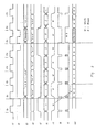
- the clock signal on the conversion clock signal line 11 is input to the counter 113, which generates conversion cycle signals on the conversion cycle signal (counter value) line 14. These conversion cycle signals are counter values which are counted as the counter is clocked. Input data on the input bit signal line 13 is applied to the conversion table 111 together with a conversion cycle signal and a conversion output is read out from the conversion table 111.
- the signal on line 15 is a conversion end flag signal
- the signal on the line 16 is a partial bit length signal which indicates the length (e.g.
- the signal on the line 17 is a code output signal indicating whether the partial bit length signal relates to a code value 1 or to a code value 0 (black or white in terms of image data).
- the signal on the bit train update signal line 12 used for updating the bit train on the input bit signal line 13 provides the split bit train to be converted next, by detecting the conversion end flag signal (e.g. in this case, each update signal causes a next split train of eight bits to be delivered).
- the signal on the code output change detecting signal line 18 is used for detecting a change in the signal on the code output signal line 17 and is provided as an output of code output change detecting means which are composed of D-type flip-flop 114, which receives input data from the code output signal line 17 and a clock input from the conversion clock signal line 11, and the exclusive OR gate 115.
- the code change detecting signal on line 18 When the code change detecting signal on line 18 is 0, the content of a partial bit length output signal relating to the period just before the particular conversion clock signal in question (to the end of one split train), being stored in the register 116, is input as an adder value signal to the adder 112 and it is added to the partial bit length output signal relating to the period following the particular conversion clock signal (the beginning of the next split train). Thereby, an added partial bit length output can be obtained.
- addition control in dependence upon the signal on the code output change detecting signal line 18 is carried out for adding partial bit length output signals, conversion outputs of conversion table 111, for obtaining a larger bit length value in a case in which no code change occurs between the split bit train (in a case in which both before and after the split white or black code values are obtained; i.e. when one code value is found on both sides of the split).
- Each circuit of Figure 1 changes status (if appropriate) as the rising portion of a clock signal on the conversion clock signal line 11.
- the signal on the bit train update signal line 12 is formed so that the bit train (on the input signal line) is updated at the rising portion of the signal on line 12 (i.e. the next split train is then delivered).
- the conversion end flag signal (line 15), partial bit length signal (line 16) and the code output signal (line 17), which indicates whether the partial bit length signal relates to a code value 1 or a code value 0 in a bit train, are output but a considerable time is required to elapse before the code output signal (line 17) is stabilized after rise of a clock signal on the conversion table 111 because the conversion table 111 provides a delay time since it is a memory.
- the code output change detection signal (line 18) and added value signal (line 19) change meaninglessly for a time and are considered as invalid during that time (refer to the hatched areas of Figure 2).
- the conversion table output (lines 15, 16, 17) from the time t, initially becomes black 1 (the code output signal line 17 indicates black by carrying a code value 1, whilst the partial bit length signal ine 16 indicates the length of black, that is, the number of consecutive occurrences of bits having a black value 1 in input data, by carrying a bit length of 1).
- the length on the partial bit length signal line is input to the adder 112.
- the inputs to the conversion table are the input bit signal shown at 13 in Figure 2 (10011100) at the relevant time, and the conversion cycle signal shown at 14 in Figure 2 (which is initially 000).
- the signal on the added value signal line 19 is not input to the adder 112 if the code output signal line 17 shows a change in code output (i.e.
- the white 2 code value which is the result of conversion at time t 4 is input to the adder 112 and it is this which is provided as the added value signal which is then added to the conversion table output at time t s .
- the result of addition is output on conversion result output line 110 at time t s .
- the image data conversion method explained with reference to Figures 1 to 4 requires a clock cycle which is the same as that of previously proposed systems for conversion of a pattern in which 1 and 0 appear alternately in the bit information, but significant improvement can be obtained, such that conversion can be affected at high speed with a lesser number of clocks (about a half of the previously proposed system in this example) as compared with the previously proposed systems, in a case in which 1 or 0 occurs several times consecutively, in input bit information describing a pattern.
- a line starts with a character and the last character on the line is followed by a character interval B.
- Permissible combinations of values of parameters M, N, B when the unit bit size of a character (A) is 16 are shown in Table 1.
- the number of characters on a line, the character size and character interval must be such that character size plus character interval is a divisor of the number of picture elements on the line.
- a desired size of character and a desired character interval cannot be selected at will.
- This invention overcomes this problem by a method as explained below and makes it possible to select for each individual line a desired size of character and a desired character interval.
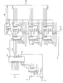
- FIG. 6 is a block circuit diagram of a circuit in which control is effected by an MPU (microprocessor unit).
- 10 is a (code memory) circuit for storing code information.
- the circuit 10 is made up of RAM (random access memory) into which a desired character code can be written from MPU.
- the counter 28 executes processing, for example sequentially reading character codes from the memory 10.
- 30, 32 are registers, into which the character enlargement coefficient N and character interval B are respectively set by the MPU.
- CG character generator
- ROM read only memory
- code converter 12 will be given with reference to Figures 7(a) to 7(d).
- 34 and 36 are the character generator CG and ROM mentioned above and 38 and 40 are counters which are operable to output part address signals for making access to CG and ROM.
- character codes A o to A 5 input from the code memory 10, are "100000", corresponding to a character "A"
- these codes are input CG 34 as a part of an address signal therefor and a 3-bit output of the counter 38 is input to CG 34 as the remaining part of the address signal.
- the former address signal part (A o to A 5 ) designates the character and the latter address signal part designates a particular line of the character and pattern signals (image data) Do to D 6 relating to the pertinent line of the character are output.
- a clock signal S 1 is input to the counter 38 and thereby the counter value held in the counter is incremented by +1 and image data corresponding to the next line is output.
- 3-bits in the former and latter halves of the character codes A o to A 5 designate rows and columns of character pattern groups arranged in the form of matrices.
- character patterns of a total of 16x16 dots as explained above are used and a considerable number of characters are used.
- Image data Do to D 6 sent from character generator CG in combination with the 4-bit output of the counter 40 becomes an address signal for ROM 36, and the ROM 36, which is to be accessed by the address signal, sequentially outputs runlength codes (each 0 0 to O 5 ).
- runlength codes each 0 0 to O 5
- runlength codes white 2, black 3, white 2, white 0 are sequentially output.
- the last white 0 corresponds to the character interval and is applied to all CG outputs.
- the counter 40 is reset at the timing following the output of the last white 0 and gets ready for runlength code conversion in respect of next image data.
- S 2 is a clock signal for incrementing the counter 40 by +1.
- 0 0 , 0 1 , O2, 0 3 of a runlength code corresponding to image data indicate the number of whites or blacks, indicating respectively the values (1 or 0) of 2°, 2 1 , 2 2 , 2 3 which together make up the number.
- O 4 indicates whether the runlength is for white or black; indicating black when it is 1 and white when it is 0.
- 0 5 is used for resetting the counter 40 and reading a next character code. When 0 5 is 1 this resets the counter 40 and reads the next character code.
- the counter increments by +1 and the output A 7 to A 10 becomes 1000.
- the output A o to As does not change.
- Figure 6 14 is a multiplier composed of ROM.
- This multiplier outputs runlengthxN (data being written in the ROM in such a manner as to provide this) in accordance with an address given by the runlength (RL) code output of code convertor 12 and the output N (character enlargement coefficient) of the register 30.
- runlength codes from 12
- Runlength codes can be multiplied by N easily.
- the character interval B is set as white 0, namely as 00000. Thereby, it is 0 when it is multiplied by N, making operations for character enlargement easy.
- 16 is the character interval insertion circuit comprising adders ADD and multipliers MPX. This circuit has a structure as shown in Figure 9.
- 18, 20 and 22 are a multiplexer, an adder and a register and operate as runlength code adders.
- the MPX 18 selects an initial value S (see the remainder mentioned above) sent from MPU and this is set in the register 22. Thereafter, MPX 18 selects the character interval insertion circuit 16 and causes the adder 20 to add the appropriate white or black runlength codes. For example, if the initial value S indicates a white interval, and the first output of the circuit 16 after taking S is white x1, the adder 20 is caused to provide S+x1. In a case in which a character then appears, the runlength code becomes black x2 and addition of white runlengths is terminated.
- Buffer 24 is a fast-in, fast-out (first-in, first-out) type register and it is intended to absorb the runlength calculation time which changes depending upon the image pattern.
- 26 is a circuit which converts runlength code into one-dimensional coding code.
- circuit 26 is composed of ROM and stores in advance data and numbers of bits of primarily compressed code corresponding to runlength code, and in operation outputs corresponding primarily compressed code. Examples of the code conversion carried out by the conversion circuit 26 are shown in Table 2 and Table 3.
- runlength code sent from the buffer 24 white and black runlengths appear alternately and these are converted to codes as indicated in Table 2 and Table 3 by the circuit 26.
- Runlengths in the range 0 to 63 are coded in terms only of terminating codes (Table 2).
- For runlengths of 64 or more make-up codes (Table 3) which indicate a runlength equal to or shorter than the actual runlength are first used and thereafter remaining runlength is indicated by a terminating code.
- An output of the converter circuit 26 is transmitted to a remote facsimile receiver via a modem and transmission line.
- the embodiment illustrated with reference to Figure 6 to 10 realises effective and simultaneous runlength conversion operations, character enlargement and character interval inserting operations by providing multiplier 14, character interval inserting circuit 16 and multiplexer 18 between the conversion table 111 and adder 112 shown in Figure 1.
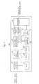
- FIG 11 is a block diagram of facsimile communication equipment employing character code/ character pattern conversion apparatus as explained with reference to Figures 6 to 10.
- the character code/character pattern compression converter 66 corresponds to the circuit of Figure 6.
Landscapes
- Engineering & Computer Science (AREA)
- Theoretical Computer Science (AREA)
- Physics & Mathematics (AREA)
- Mathematical Physics (AREA)
- General Engineering & Computer Science (AREA)
- General Physics & Mathematics (AREA)
- Multimedia (AREA)
- Signal Processing (AREA)
- Image Processing (AREA)
- Editing Of Facsimile Originals (AREA)
- Controls And Circuits For Display Device (AREA)
Claims (10)
Applications Claiming Priority (4)
| Application Number | Priority Date | Filing Date | Title |
|---|---|---|---|
| JP56032126A JPS57168570A (en) | 1981-03-06 | 1981-03-06 | Character code-to-character pattern converter |
| JP32126/81 | 1981-03-06 | ||
| JP35034/81 | 1981-03-11 | ||
| JP3503481A JPS57197961A (en) | 1981-03-11 | 1981-03-11 | Conversion system for image data |
Publications (3)
| Publication Number | Publication Date |
|---|---|
| EP0060101A2 EP0060101A2 (de) | 1982-09-15 |
| EP0060101A3 EP0060101A3 (en) | 1985-04-17 |
| EP0060101B1 true EP0060101B1 (de) | 1988-09-07 |
Family
ID=26370650
Family Applications (1)
| Application Number | Title | Priority Date | Filing Date |
|---|---|---|---|
| EP82301125A Expired EP0060101B1 (de) | 1981-03-06 | 1982-03-05 | Bilddatenumwandlung und Zeichenkode/Zeichenmuster-Umwandlung |
Country Status (8)
| Country | Link |
|---|---|
| US (1) | US4516173A (de) |
| EP (1) | EP0060101B1 (de) |
| KR (1) | KR850001657B1 (de) |
| AU (1) | AU535054B2 (de) |
| BR (1) | BR8201171A (de) |
| CA (1) | CA1186057A (de) |
| DE (1) | DE3279020D1 (de) |
| ES (1) | ES510191A0 (de) |
Families Citing this family (18)
| Publication number | Priority date | Publication date | Assignee | Title |
|---|---|---|---|---|
| US4644545A (en) * | 1983-05-16 | 1987-02-17 | Data General Corporation | Digital encoding and decoding apparatus |
| US4542413A (en) * | 1983-08-19 | 1985-09-17 | Advanced Micro Devices, Inc. | Facsimile device for run length coding |
| US4610027A (en) * | 1983-12-30 | 1986-09-02 | International Business Machines Corporation | Method for converting a bit map of an image to a run length or run end representation |
| EP0158311A3 (de) * | 1984-04-06 | 1989-04-26 | Nec Corporation | Gerät zur Wiederauffindung von Zeichenketten |
| US4885786A (en) * | 1984-10-24 | 1989-12-05 | International Business Machines Corporation | Method for enlarging an image stored in run representation form |
| US4817187A (en) * | 1987-02-19 | 1989-03-28 | Gtx Corporation | Apparatus and method for vectorization of incoming scanned image data |
| US4870498A (en) * | 1987-09-15 | 1989-09-26 | Printware, Inc. | Decompressing run-length-encoded to transition-encoded font image information in an image generator |
| JPS6478381A (en) * | 1987-09-21 | 1989-03-23 | Toshiba Corp | Picture processing method |
| US4792981A (en) * | 1987-09-21 | 1988-12-20 | Am International, Inc. | Manipulation of run-length encoded images |
| US5471676A (en) * | 1989-10-17 | 1995-11-28 | Nakajima All Precision Co., Ltd. | Character data compressing method and character modifying method |
| US5299294A (en) * | 1991-10-01 | 1994-03-29 | Xerox Corporation | Method for compensating for font resolution conversion error |
| DE69328325T2 (de) * | 1992-05-18 | 2000-08-24 | Canon K.K., Tokio/Tokyo | Kodierungs- und Dekodierungsvorrichtung |
| TW247952B (de) * | 1992-07-09 | 1995-05-21 | Seikosha Kk | |
| JP2842781B2 (ja) * | 1993-12-24 | 1999-01-06 | 日本電気株式会社 | 画像情報処理方式 |
| JP3986098B2 (ja) * | 1994-08-16 | 2007-10-03 | 富士通株式会社 | 文字列検索方法及び文字列検索装置 |
| US5757966A (en) * | 1995-07-11 | 1998-05-26 | Xerox Corporation | High-speed encoder |
| US7348983B1 (en) * | 2001-06-22 | 2008-03-25 | Intel Corporation | Method and apparatus for text image stretching |
| JP3870171B2 (ja) * | 2003-03-11 | 2007-01-17 | キヤノン株式会社 | 符号化方法及び符号化装置、コンピュータプログラム並びにコンピュータ可読記憶媒体 |
Family Cites Families (7)
| Publication number | Priority date | Publication date | Assignee | Title |
|---|---|---|---|---|
| US3828319A (en) * | 1969-06-23 | 1974-08-06 | Ipc Service Ltd | Composition system |
| US4135214A (en) * | 1969-07-02 | 1979-01-16 | Dacom, Inc. | Method and apparatus for compressing facsimile transmission data |
| US3911420A (en) * | 1973-11-23 | 1975-10-07 | Xerox Corp | Display system including a high resolution character generator |
| JPS5258406A (en) * | 1975-11-10 | 1977-05-13 | Kokusai Denshin Denwa Co Ltd | Facsimile signal change point address coding system |
| US4107662A (en) * | 1976-02-17 | 1978-08-15 | Hitachi, Ltd. | Character generator for visual display devices |
| JPS52105734A (en) * | 1976-03-01 | 1977-09-05 | Canon Inc | Signal coverter |
| US4079458A (en) * | 1976-08-11 | 1978-03-14 | Xerox Corporation | High resolution character generator |
-
1982
- 1982-02-27 KR KR8200869A patent/KR850001657B1/ko not_active Expired
- 1982-03-01 US US06/353,334 patent/US4516173A/en not_active Expired - Fee Related
- 1982-03-04 AU AU81121/82A patent/AU535054B2/en not_active Ceased
- 1982-03-05 DE DE8282301125T patent/DE3279020D1/de not_active Expired
- 1982-03-05 EP EP82301125A patent/EP0060101B1/de not_active Expired
- 1982-03-05 CA CA000397692A patent/CA1186057A/en not_active Expired
- 1982-03-05 ES ES510191A patent/ES510191A0/es active Granted
- 1982-03-05 BR BR8201171A patent/BR8201171A/pt unknown
Non-Patent Citations (1)
| Title |
|---|
| IEEE-ICC 79 Conference Record, vol. 1-4, 10-14 Juni 1979, pp. 8.7.1-3.7.5 (79CH1435-7CSCB) * |
Also Published As
| Publication number | Publication date |
|---|---|
| AU535054B2 (en) | 1984-03-01 |
| ES8305546A1 (es) | 1983-04-01 |
| KR850001657B1 (ko) | 1985-11-06 |
| DE3279020D1 (en) | 1988-10-13 |
| AU8112182A (en) | 1982-11-25 |
| EP0060101A3 (en) | 1985-04-17 |
| BR8201171A (pt) | 1983-01-18 |
| US4516173A (en) | 1985-05-07 |
| ES510191A0 (es) | 1983-04-01 |
| KR830009842A (ko) | 1983-12-23 |
| EP0060101A2 (de) | 1982-09-15 |
| CA1186057A (en) | 1985-04-23 |
Similar Documents
| Publication | Publication Date | Title |
|---|---|---|
| EP0060101B1 (de) | Bilddatenumwandlung und Zeichenkode/Zeichenmuster-Umwandlung | |
| US4271476A (en) | Method and apparatus for rotating the scan format of digital images | |
| EP0030437B1 (de) | Verfahren und Apparat zur Kompression und Dekompression digitaler Bilddaten | |
| US5483622A (en) | Page printer having automatic font compression | |
| US4843632A (en) | Compressed image expansion system | |
| US4168513A (en) | Regenerative decoding of binary data using minimum redundancy codes | |
| US4135214A (en) | Method and apparatus for compressing facsimile transmission data | |
| TW371340B (en) | Image processing system | |
| US5457772A (en) | Method to convert bitmaps to monochrome data | |
| EP0199065B1 (de) | Verfahren und Vorrichtung zur Datenkompression in einer Faksimile-Übertragungsanordnung | |
| US7555170B2 (en) | Image processing apparatus for scaling images | |
| JPS58127466A (ja) | 画像拡大縮小方式 | |
| US4799110A (en) | Image signal coding apparatus | |
| EP0063144B1 (de) | Verfahren und anordnung zum zwischenspeichern von daten | |
| US5548689A (en) | Method to convert bitmaps to monochrome data | |
| US4058674A (en) | Graphic information compression method and system | |
| EP0048625B1 (de) | Schnittstelleneinheit für Druckwerk zur Datenumwandlung | |
| US6266446B1 (en) | Image conversion between raster and block formats for compression and decompression | |
| JP3116989B2 (ja) | 圧縮された2値画像データの復元装置 | |
| EP0558292B1 (de) | Schaltung zur Kompression/Expansion | |
| US5444832A (en) | Pixel density converter | |
| JPH09154021A (ja) | 印字制御装置と印字制御方法 | |
| CA1195428A (en) | Image data conversion method and character code/character pattern conversion apparatus | |
| JPS63190473A (ja) | 多階調画像デ−タの情報量圧縮方法及び装置 | |
| KR900007566B1 (ko) | 화상데이터 변환장치 및 방법 |
Legal Events
| Date | Code | Title | Description |
|---|---|---|---|
| PUAI | Public reference made under article 153(3) epc to a published international application that has entered the european phase |
Free format text: ORIGINAL CODE: 0009012 |
|
| AK | Designated contracting states |
Designated state(s): DE FR GB |
|
| PUAL | Search report despatched |
Free format text: ORIGINAL CODE: 0009013 |
|
| AK | Designated contracting states |
Designated state(s): DE FR GB |
|
| 17P | Request for examination filed |
Effective date: 19850422 |
|
| 17Q | First examination report despatched |
Effective date: 19870130 |
|
| GRAA | (expected) grant |
Free format text: ORIGINAL CODE: 0009210 |
|
| AK | Designated contracting states |
Kind code of ref document: B1 Designated state(s): DE FR GB |
|
| REF | Corresponds to: |
Ref document number: 3279020 Country of ref document: DE Date of ref document: 19881013 |
|
| ET | Fr: translation filed | ||
| PGFP | Annual fee paid to national office [announced via postgrant information from national office to epo] |
Ref country code: GB Payment date: 19890228 Year of fee payment: 8 |
|
| PGFP | Annual fee paid to national office [announced via postgrant information from national office to epo] |
Ref country code: FR Payment date: 19890330 Year of fee payment: 8 |
|
| PGFP | Annual fee paid to national office [announced via postgrant information from national office to epo] |
Ref country code: DE Payment date: 19890523 Year of fee payment: 8 |
|
| PLBE | No opposition filed within time limit |
Free format text: ORIGINAL CODE: 0009261 |
|
| STAA | Information on the status of an ep patent application or granted ep patent |
Free format text: STATUS: NO OPPOSITION FILED WITHIN TIME LIMIT |
|
| 26N | No opposition filed | ||
| PG25 | Lapsed in a contracting state [announced via postgrant information from national office to epo] |
Ref country code: GB Effective date: 19900305 |
|
| GBPC | Gb: european patent ceased through non-payment of renewal fee | ||
| PG25 | Lapsed in a contracting state [announced via postgrant information from national office to epo] |
Ref country code: FR Effective date: 19901130 |
|
| PG25 | Lapsed in a contracting state [announced via postgrant information from national office to epo] |
Ref country code: DE Effective date: 19901201 |
|
| REG | Reference to a national code |
Ref country code: FR Ref legal event code: ST |