EP0060896B1 - Main pour un robot industriel - Google Patents
Main pour un robot industriel Download PDFInfo
- Publication number
- EP0060896B1 EP0060896B1 EP81902731A EP81902731A EP0060896B1 EP 0060896 B1 EP0060896 B1 EP 0060896B1 EP 81902731 A EP81902731 A EP 81902731A EP 81902731 A EP81902731 A EP 81902731A EP 0060896 B1 EP0060896 B1 EP 0060896B1
- Authority
- EP
- European Patent Office
- Prior art keywords
- pair
- gripping fingers
- workpiece
- hand
- gripping
- Prior art date
- Legal status (The legal status is an assumption and is not a legal conclusion. Google has not performed a legal analysis and makes no representation as to the accuracy of the status listed.)
- Expired
Links
- 210000000707 wrist Anatomy 0.000 claims description 6
- 210000000078 claw Anatomy 0.000 claims description 5
- 239000012530 fluid Substances 0.000 claims description 5
- 230000001788 irregular Effects 0.000 claims description 2
- 230000000694 effects Effects 0.000 description 4
- 230000001965 increasing effect Effects 0.000 description 4
- 230000007935 neutral effect Effects 0.000 description 3
- 238000010586 diagram Methods 0.000 description 2
- 238000000034 method Methods 0.000 description 2
- 230000007547 defect Effects 0.000 description 1
- 230000002708 enhancing effect Effects 0.000 description 1
- 230000004048 modification Effects 0.000 description 1
- 238000012986 modification Methods 0.000 description 1
Images

Classifications
-
- B—PERFORMING OPERATIONS; TRANSPORTING
- B25—HAND TOOLS; PORTABLE POWER-DRIVEN TOOLS; MANIPULATORS
- B25J—MANIPULATORS; CHAMBERS PROVIDED WITH MANIPULATION DEVICES
- B25J1/00—Manipulators positioned in space by hand
-
- B—PERFORMING OPERATIONS; TRANSPORTING
- B25—HAND TOOLS; PORTABLE POWER-DRIVEN TOOLS; MANIPULATORS
- B25J—MANIPULATORS; CHAMBERS PROVIDED WITH MANIPULATION DEVICES
- B25J15/00—Gripping heads and other end effectors
- B25J15/08—Gripping heads and other end effectors having finger members
- B25J15/10—Gripping heads and other end effectors having finger members with three or more finger members
Definitions
- the present invention relates to an industrial robot. More particularly, the present invention relates to an improvement of the structure of a gripping finger of a hand of an industrial robot for increasing the gripping function of the hand.
- Industrial robots are now used widely in various fields for holding and delivering articles having a heavy weight or holding and delivering workpieces of machine tools.
- the application range of an industrial robot is especially broadened, and the weight of articles to be gripped (hereinafter referred to as "workpieces") is increasing and the shape of workpieces is diversified, causing the holding and delivering to become complicated.
- industrial robots able to accomplish holding and delivering heavy workpieces of diversified shapes greatly contribute to enhancing the labor-saving effect.
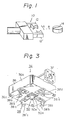
- a robot hand for example, the robot hand 10 shown in Fig. 1, effects the gripping and delivering operation. More specifically, in Fig.
- the robot hand 10 has gripping fingers 12 and 12' opening and closing in the direction indicated by an arrow A, that is, in the lateral direction, and the hand 10 is brought close to a workpiece 14 in the lateral direction, that is, in the direction indicated by an arrow B, and the gripping fingers 12 and 12' are closed to grip the workpiece 14 therebetween.
- this gripping method since the workpiece is gripped only at two confronting positions on the side face of the workpiece, the gripping state often becomes unstable when the weight of the workpiece is very heavy and/or when the workpiece has an angular plane shape, though the method is suitable for gripping and delivering a workpiece having a circular plane shape or a relatively light weight.
- a hand of an industrial robot for gripping a workpiece of irregular shape comprising:
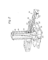
- Fig. 2 is a perspective view showing the appearance of an industrial robot provided with one embodiment of the industrial robot hand according to the present invention.
- reference numeral 20 represents a stationary base of an industrial robot, and a turntable 22 is arranged on this stationary base 20 so that the turntable 22 can rotate in both the normal and reverse directions.
- Two vertical guide shafts are mounted on the turntable 22 to support a robot casing 26 movable in the vertical direction. Only one guide shaft 24 is visible the second one is hidden by the vertical support member.
- a vertical feed screw shaft 28 is arranged parallel to the vertical guide shafts 24 and 24' and is threadedly engaged with the robot casing 26, so that the robot casing 26 is vertically moved along the guide shafts 24 and 24' according to the rotation of the vertical feed screw shafts 28.
- the robot casing 26 supports robot arms 30 and 30' so that the robot arms 30 and 30' are extended and contracted in the axial direction, and a robot hand 34, according to the present invention, is attached to the ends of the robot arms 30 and 30' through a wrist mechanism portion 32.
- the hand 34 is arranged so that the rotating position and swinging position of the hand 34 can be determined by the operation of the wrist mechanism portion 32.
- Fig. 3 is a perspective view showing the appearance of a hand 34 according to one embodiment of the present invention.
- reference numeral 34 represents the hand as a whole.
- the lower face of a hand base plate member 36 that is, the face gripping a workpiece, is called a "palm face” 36a, and the opposite face is called “back face” 36b.
- Gripping fingers 38 are arranged so that they extend in the direction perpendicular to the palm face 36a of the base plate member 36 of the hand 34, and the gripping fingers 38 consist of two pairs of fingers, that is, fingers 38a and 38b and finger 38c and 38d.
- the first pair of the gripping fingers 38a and 38b are arranged symmetrically with each other with respect to the center of the palm face 36a to confront each other, and these fingers 38a and 38b are constructed so that they move toward the center of the palm face 36a parallel to the palm face 36a synchronously with each other to effect the opening and closing operation and, thereby, come to hold a workpiece.
- the second pair of fingers 38c and 38d are constructed and arranged in the same manner as the first pair of fingers 38a and 38b, except that the opening and closing direction of the fingers 38c and 38d intersects the opening and closing direction of the fingers 38a and 38b at a right angle.
- a mechanism for opening and closing these fingers such as a link mechanism, as shown in Fig. 4, an air cylinder or a changeover solenoid valve, is arranged for each pair of the gripping fingers, so that the respective pairs of the gripping fingers are opened and closed synchronously or independently.
- Inwardly bent hook claws 38'a, 38'b, 38'c and 38'd are mounted on the top ends of the gripping fingers 38, respectively, and a gripped workpiece is anchored by these hook claws to prevent the workpiece from falling. Accordingly, even a workpiece having a heavy weight can be securely held and delivered safely.
- a pressing device 50 is disposed in the central portion of the palm face 36a, and this pressing device 50 comprises a fixing portion 50a and a pressing finger 50b.
- an actuator for example, a fluid cylinder (not shown)
- the pressing finger 50b is appropriately actuated to press the workpiece so that the workpiece is securely anchored by the hook claws 38'a, 38'b, 38'c and 38'd, but not held in the biased state.
- An attachment bracket 37 is mounted on the back face 36b of the hand base plate member 36, and the attachment bracket 37 is formed so that it can be attached to the wrist mechanism portion 32, as shown in Fig. 2.
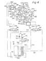
- Fig. 4 shows an example of the structure of an apparatus for operating the hand 34.
- the first pair of the fingers 38a and 38b are slidably connected to guide shafts 40a and 40b secured to a stationary bracket 46 through gripping finger supporting bracket 42a and 42b, respectively.
- the top end portions of the supporting brackets 42a and 42b are slidably and rotatably connected to both the ends of a link 44 through pins 44a and 44b.
- the central portion of the link 44 is supported on the stationary bracket 46 through a pin 44e so that the link 44 can turn.
- An operating portion of the actuator for example, a piston rod 48b of an air cylinder 48, is connected to the end portion of an operating bracket 42e secured to the base end of one 42a of the supporting brackets 42a and 42b. Accordingly, with the reciprocative movement of the piston 48a of the air cylinder 48, the gripping fingers 38a and 38b are moved, parallel with each other, along the guide shafts 40a and 40b through the above-mentioned link mechanism, so that the fingers 38a and 38b confront each other and effect the opening and closing operation.
- the second pair of the gripping fingers 38c and 38d are arranged so that the opening and closing direction of the fingers 38c and 38d intersects the opening and closing direction of the fingers 38a.and 38b at a right angle.
- the gripping fingers 38c and 38d are opened and closed along guide shafts 40c and 40d by the air cylinder 48' through a link mechanism having the same structure as that of the link mechanism for the first pair of the gripping fingers 38a and 38b, which is arranged on the opposite side of the stationary bracket 46 and comprises guide shafts 40c and 40d, gripping finger supporting brackets 42c and 42d, an operating bracket 42f, pins 44c, 44d and 44e and a link 44'.
- Reference numeral 52 represents a robot control apparatus 52, and each of reference numerals 52a, 52b, 52c, 52d and 52e represents an electric signal line.
- Reference numeral 54 represents a compressed air source and each of reference numerals 54a, 54b, 54c, 54d, 54e, 54f, 54g and 54h represents an air passage.
- Each of reference numerals 56, 58 and 58' represents a changeover solenoid valve for controlling the direction of the air passage, and these changeover solenoid valves perform a changeover operation based on electric signals from the robot control apparatus 52. More specifically, referring to Fig. 4, by the changeover operation of the changeover solenoid valve 56, the passage 54h is connected to one of the passages 54f or 54g.
- compressed air (hereinafter referred to as "air”) flowing in the passage 54f passes through a check valve 55 and flows in the passage 54e with the same air pressure as the air pressure at the air source 54.
- the pressure of air flowing in the passage 54g is reduced to a predetermined level by a pressure reducing valve 60, and this air passes through a check valve 55' and flows into the passage 54e.
- the gripping force of the hand can appropriately be selected according to the weight of a workpiece, and a high air pressure or a low pressure is appropriately chosen, whereby wasteful consumption of air can be avoided and air can be used at a high efficiency.
- the air pressure is controlled at two levels.
- an air pressure control apparatus capable of multi- staged air pressure control, can be constructed.
- the changeover solenoid valves 58 and 58' have the same structure.
- the passage 54e is selectively connected to the passage 54a or 54b, and, by this changeover operation, air is introduced alternately into cylinder chambers 48c and 48d of the cylinder 48 to move the piston 48a reciprocatively.
- the solenoid valve 58 is set at the neutral position
- the passage 54e is shut to intercept the air flowing into the passage 54a or 54b. If both the changeover solenoid valves 58 and 58' are simultaneously set at the neutral positions, or if one or the other of these valves 58 and 58' is set at the neutral position, the first pair of the gripping fingers 38a and 38b and the second pair of the gripping fingers 38c and 38d can be opened and closed synchronously or independently.
- the pressing device 50 shown in Fig. 3, is not shown in Fig. 4. However, the pressing device can also be easily constructed and assembled in Fig. 4 by appropriately arranging related members, such as changeover solenoid valves and air cylinders.
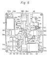
- Fig. 5 is a front view of the hand seen from the side of the palm face, which illustrates an embodiment of the arrangement of the respective members shown in Fig. 4.
- Reference numerals in Fig. 5 represent the same members as in Fig. 4.
- reference numeral 62 in Fig. 5 represents a changeover solenoid valve 62 for the D ressina device (50 in Fig. 3).
- Fig. 6 is a time chart of electric signals S52a, S52b, S52c, S52d and S52e transmitted from the robot control apparatus 52 through the signal lines 52a, 52b, 52c, 52d and 52e, respectively.
- the signal S52e on the signal line 52e shown in Fig. 4
- the signal S52b on the signal line 52b is maintained at a high level, whereby the gripping fingers 38a and 38b are caused to grip the workpiece with a weak gripping force.
- the control apparatus 52 the signal S52e on the signal line 52e is maintained at a low level and the signal S52c on the signal line 52c is maintained at a high level, whereby the gripping fingers 38c and 38d are caused to grip the workpiece with a strong gripping force.
- the center of the workpiece is deviated from the moving direction of the gripping fingers 38c and 38d, since the gripping force of the gripping fingers 38c and 38d is larger than the gripping force of the gripping fingers 38a and 38b, the center of the workpiece can be made to coincide with the gripping center of the hand.
- the signal S52b on the signal line 52b is maintained at a high level by the control apparatus 52, whereby the gripping force of the gripping fingers 38a and 38b is changed over to a strong gripping force. Then, the operation of shifting the workpiece to the instructed position is performed, and the signals on the signal lines 52a and 52d are maintained at a high level by the control apparatus 52, with the result that the fingers 38a, 38b, 38c and 38d simultaneously perform an opening operation under a strong air pressure to release the workpiece at the instructed position.
Landscapes
- Engineering & Computer Science (AREA)
- Robotics (AREA)
- Mechanical Engineering (AREA)
- Manipulator (AREA)
Claims (3)
Applications Claiming Priority (2)
| Application Number | Priority Date | Filing Date | Title |
|---|---|---|---|
| JP135258/80 | 1980-09-30 | ||
| JP55135258A JPS5761487A (en) | 1980-09-30 | 1980-09-30 | Hand for industrial robot |
Publications (3)
| Publication Number | Publication Date |
|---|---|
| EP0060896A1 EP0060896A1 (fr) | 1982-09-29 |
| EP0060896A4 EP0060896A4 (fr) | 1984-03-27 |
| EP0060896B1 true EP0060896B1 (fr) | 1986-02-19 |
Family
ID=15147495
Family Applications (1)
| Application Number | Title | Priority Date | Filing Date |
|---|---|---|---|
| EP81902731A Expired EP0060896B1 (fr) | 1980-09-30 | 1981-09-30 | Main pour un robot industriel |
Country Status (6)
| Country | Link |
|---|---|
| US (1) | US4479673A (fr) |
| EP (1) | EP0060896B1 (fr) |
| JP (1) | JPS5761487A (fr) |
| KR (1) | KR850000041B1 (fr) |
| SU (1) | SU1168090A3 (fr) |
| WO (1) | WO1982001152A1 (fr) |
Cited By (3)
| Publication number | Priority date | Publication date | Assignee | Title |
|---|---|---|---|---|
| DE3734683A1 (de) * | 1986-10-14 | 1988-04-28 | Dansk Ind Syndikat | System mit einem selbstantriebsgreifer und einer anzahl von zu greifenden gegenstaenden, insbesondere zur verwendung in einer automatisierten giessereianlage, mit fluidverbindung zwischen dem greifer und dem gerade gegriffenen gegenstand |
| DE9400777U1 (de) * | 1994-01-18 | 1994-09-29 | Protech Automation GmbH, 51147 Köln | Umsetzvorrichtung für Stapel aus parallelen Gegenständen |
| DE102024115835A1 (de) * | 2024-06-06 | 2025-12-11 | Bayerische Motoren Werke Aktiengesellschaft | Manipulatoreinrichtung eines Roboters sowie Verfahren zum Greifen eines Gegenstands durch eine derartige Manipulatoreinrichtung |
Families Citing this family (75)
| Publication number | Priority date | Publication date | Assignee | Title |
|---|---|---|---|---|
| JPS5919644A (ja) * | 1982-07-19 | 1984-02-01 | Matsushita Electric Ind Co Ltd | 部品チヤツク装置 |
| EP0114096A1 (fr) * | 1983-01-13 | 1984-07-25 | Western Electric Company, Incorporated | Bras de robot |
| JPS59201782A (ja) * | 1983-04-23 | 1984-11-15 | 大日本スクリ−ン製造株式会社 | ウエハ等の薄板物搬送装置 |
| JPS59224279A (ja) * | 1983-06-01 | 1984-12-17 | 富士機械製造株式会社 | 電子部品の位置決め保持方法および装置 |
| GB8326364D0 (en) * | 1983-10-01 | 1983-11-02 | Bull R J | Robot part |
| US4616971A (en) * | 1983-10-11 | 1986-10-14 | Fairchild Camera And Instrument Corp. | Robotic hand and method for manipulating printed circuit boards |
| US4579380A (en) * | 1983-12-06 | 1986-04-01 | Carnegie-Mellon University | Servo robot gripper |
| JPS60155325A (ja) * | 1984-01-20 | 1985-08-15 | Sanyo Electric Co Ltd | 電子部品の位置決め装置 |
| US4852928A (en) * | 1984-02-16 | 1989-08-01 | Multivisions Corporation | Robotic end effectors |
| US4591198A (en) * | 1984-02-16 | 1986-05-27 | Monforte Robotics, Inc. | Robotic end effectors |
| US4588344A (en) * | 1984-06-04 | 1986-05-13 | Essex Group, Inc. | Roll transfer robot |
| FR2582563B1 (fr) * | 1985-05-30 | 1987-07-24 | Centre Nat Rech Scient | Prehenseur tactile pneumatique developpant une force de serrage asservie au poids de l'objet manipule |
| EP0320499A3 (fr) * | 1985-07-25 | 1991-04-03 | Alfred Winter | Pince de préhension pour robot industriel |
| US4802816A (en) * | 1985-10-08 | 1989-02-07 | Excellon Industries | Pick and place machine having improved centering jaws |
| US4653794A (en) * | 1986-02-12 | 1987-03-31 | Northrop Corporation | Universal adjustable gripper with center push |
| DE3610130C2 (de) * | 1986-03-26 | 1995-01-05 | Karl Rekers Maschinenbau Fa Di | Greifvorrichtung |
| US4699414A (en) * | 1986-04-21 | 1987-10-13 | The United States Of America As Represented By The Secretary Of The Air Force | Multi use gripper for industrial robot |
| DE3624307C1 (de) * | 1986-07-18 | 1987-11-12 | Agfa Gevaert Ag | Vorrichtung zum Aufnehmen und Absetzen von Spulen |
| US4696503A (en) * | 1986-10-27 | 1987-09-29 | The Singer Company | Pneumatic actuated cam driven parallel gripper |
| US4866824A (en) * | 1986-12-04 | 1989-09-19 | Micro Component Technology, Inc. | Centering mechanism |
| US4741567A (en) * | 1987-01-12 | 1988-05-03 | Rca Corporation | Robotic system and end effector |
| US4816732A (en) * | 1987-08-17 | 1989-03-28 | Sgs Thomson Microelectronics, Inc. | Robotic hand for transporting semiconductor wafer carriers |
| ATE82889T1 (de) * | 1987-08-31 | 1992-12-15 | Siemens Ag | Loetkopf zum aufnehmen und ausrichten von bauelementen waehrend des ein- oder ausloetens, insbesondere fuer oberflaechenmontierbare bauelemente (smd). |
| JPH0613787Y2 (ja) * | 1987-12-10 | 1994-04-13 | 日産自動車株式会社 | ワーク位置決め装置 |
| JP2680128B2 (ja) * | 1989-05-30 | 1997-11-19 | 愛三工業株式会社 | 回転体を利用したワーク把持装置 |
| US5106138A (en) * | 1989-06-05 | 1992-04-21 | Hewlett-Packard Company | Linear tweezers |
| EP0402001A1 (fr) * | 1989-06-05 | 1990-12-12 | Hewlett-Packard Company | Pinces linéaires |
| US4987676A (en) * | 1989-08-23 | 1991-01-29 | Quad Systems Corporation | End effector for a robotic system |
| JPH0743056Y2 (ja) * | 1990-04-19 | 1995-10-04 | 日東工器株式会社 | 荷役機械 |
| JPH081922B2 (ja) * | 1991-01-25 | 1996-01-10 | 株式会社東芝 | ウェハ−保持装置 |
| NZ261488A (en) * | 1993-01-27 | 1996-06-25 | Warner Lambert Co | Reduced alcohol content mouthwash having at most 22% v/v alcohol |
| US5701662A (en) * | 1995-11-06 | 1997-12-30 | Matsushita Electric Industrial Co., Ltd. | Axial type electronic component inserting apparatus |
| US6588995B2 (en) * | 1997-05-13 | 2003-07-08 | The Hillman Group, Inc. | Method and apparatus for aligning keys for cutting |
| AT405701B (de) * | 1997-06-18 | 1999-11-25 | Sez Semiconduct Equip Zubehoer | Greifer für halbleiterwafer und andere scheibenförmige gegenstände |
| US6393694B2 (en) * | 1999-04-23 | 2002-05-28 | Koninklijke Philips Electronics N.V. | Gripping device |
| USD496378S1 (en) | 2003-03-04 | 2004-09-21 | Wemo Automation Ab | Gripping means for robots |
| US7370896B2 (en) * | 2003-12-30 | 2008-05-13 | Strider Labs, Inc. | Robotic hand with extendable palm |
| US9101990B2 (en) | 2006-01-23 | 2015-08-11 | Hy-Ko Products | Key duplication machine |
| EP1976656B1 (fr) | 2006-01-23 | 2014-10-29 | Hy-Ko Products Company | Machine à tailler les clés |
| AU2008255183B2 (en) * | 2007-12-10 | 2010-03-25 | Visy R & D Pty Ltd | Improvements in palletising systems |
| US20090297323A1 (en) * | 2008-05-30 | 2009-12-03 | Genesis Worldwide Ii, Inc. | Method and apparatus for stacking sheet materials |
| JP5111285B2 (ja) * | 2008-08-06 | 2013-01-09 | 株式会社日立ハイテクノロジーズ | 試料搬送機構 |
| DE102009012332A1 (de) * | 2009-03-09 | 2010-09-16 | Weber Maschinenbau Gmbh Breidenbach | Produktgreifer |
| US8634655B2 (en) | 2009-05-01 | 2014-01-21 | Hy-Ko Products Company | Key blank identification system with bitting analysis |
| MX343763B (es) | 2009-05-01 | 2016-11-18 | Hy-Ko Products | Sistema de identificación de llave en blanco con exploración digital de ranura. |
| CN101628664B (zh) * | 2009-05-07 | 2011-08-31 | 济南大学 | 汽车车轮视觉夹持器 |
| JP5738549B2 (ja) * | 2009-07-22 | 2015-06-24 | 株式会社Sumco | 包装済石英ガラスルツボ用クレーン装置およびこの装置を用いる包装済石英ガラスルツボの梱包方法 |
| CN102485442B (zh) * | 2010-12-04 | 2014-08-20 | 鸿富锦精密工业(深圳)有限公司 | 柔性抓取装置 |
| JP5993539B2 (ja) | 2011-01-06 | 2016-09-14 | セイコーエプソン株式会社 | ロボットハンド及びロボット |
| JP5834480B2 (ja) * | 2011-05-11 | 2015-12-24 | セイコーエプソン株式会社 | ロボットハンド及びロボット |
| CN103029127B (zh) * | 2011-09-30 | 2015-04-15 | 鸿富锦精密工业(深圳)有限公司 | 机器人手爪 |
| CN102530547B (zh) * | 2012-01-20 | 2014-04-16 | 刘亢 | 取杯机 |
| ITBS20120095A1 (it) * | 2012-06-19 | 2013-12-20 | Gimatic Spa | Pinza a tre griffe |
| JP5983080B2 (ja) * | 2012-06-20 | 2016-08-31 | セイコーエプソン株式会社 | ロボットハンド、ロボット、および把持機構 |
| JP5970708B2 (ja) * | 2012-07-18 | 2016-08-17 | セイコーエプソン株式会社 | ロボットハンド、ロボット、および把持機構 |
| JP6045333B2 (ja) * | 2012-12-26 | 2016-12-14 | 川崎重工業株式会社 | ロボットハンドおよびそれを備えたロボット |
| JP5835276B2 (ja) * | 2013-06-24 | 2015-12-24 | 株式会社安川電機 | ロボット、ロボットの製造方法および袋体 |
| DE202014001939U1 (de) * | 2014-02-28 | 2015-05-29 | Liebherr-Verzahntechnik Gmbh | Handhabungsvorrichtung |
| CN104175310A (zh) * | 2014-08-22 | 2014-12-03 | 苏州昌飞自动化设备厂 | 色选组合机械手的升降式机械手 |
| CN104175323A (zh) * | 2014-08-22 | 2014-12-03 | 苏州昌飞自动化设备厂 | 色选组合机械手的四爪机械气夹爪 |
| WO2016052632A1 (fr) * | 2014-09-30 | 2016-04-07 | 株式会社カネカ | Système de transfert d'échantillon et procédé de production de cellule solaire |
| USD756431S1 (en) * | 2015-05-19 | 2016-05-17 | F. Richard Langner | Robot accessory mount |
| US9486927B1 (en) | 2015-05-20 | 2016-11-08 | Google Inc. | Robotic gripper with multiple pairs of gripping fingers |
| US9818041B2 (en) | 2015-08-03 | 2017-11-14 | Hy-Ko Products Company | High security key scanning system |
| JP2016032865A (ja) * | 2015-10-30 | 2016-03-10 | セイコーエプソン株式会社 | ロボットハンド |
| CA2923047C (fr) * | 2016-03-08 | 2023-06-27 | Darcy Goossen | Dispositif de manutention de pneus |
| CN108527149B (zh) * | 2018-04-27 | 2025-02-11 | 上海发那科机器人有限公司 | 一种钣金电控柜打磨搬运机器人手爪 |
| ES2747874A1 (es) * | 2018-09-11 | 2020-03-11 | Akyurek Kardesler Tarim Urunleri Makinalari Tasimacilik Ve Madencilik Sanayi Ticaret Ltd Sirketi Suc | Maquina de empaquetado de tubos cilindricos y proceso deempaquetado |
| US11628561B2 (en) | 2019-08-19 | 2023-04-18 | The Hong Kong University Of Science And Technology | System and methods for robotic precision placement and insertion |
| US11154993B2 (en) | 2019-12-11 | 2021-10-26 | Delaware Capital Formation, Inc. | Tool changer |
| USD934321S1 (en) * | 2019-12-27 | 2021-10-26 | Evodyne Robotics Corporation | Gripper |
| DE102020110228A1 (de) * | 2020-04-15 | 2021-10-21 | Bayerische Motoren Werke Aktiengesellschaft | Vorrichtung sowie Verfahren zum Greifen eines Objekts |
| US12240073B2 (en) | 2021-09-29 | 2025-03-04 | Stabilus Motion Controls Gmbh | Tool changer |
| US20250207386A1 (en) * | 2023-12-26 | 2025-06-26 | PRAK Energy Inc. | Construction system for erecting high-rise load-bearing frame structure |
| CN120715862A (zh) * | 2025-08-27 | 2025-09-30 | 哈尔滨工业大学 | 一种高压气体内循环式的气动外骨骼机器人 |
Citations (2)
| Publication number | Priority date | Publication date | Assignee | Title |
|---|---|---|---|---|
| JPS5023191B2 (fr) * | 1971-10-16 | 1975-08-06 | ||
| JPS5445071A (en) * | 1977-09-12 | 1979-04-10 | Yamatake Honeywell Co Ltd | Robot hand |
Family Cites Families (9)
| Publication number | Priority date | Publication date | Assignee | Title |
|---|---|---|---|---|
| US3873941A (en) * | 1973-05-30 | 1975-03-25 | Coherent Radiation | Dye laser having non-colinear optical pumping means |
| JPS50101282A (fr) * | 1974-01-14 | 1975-08-11 | ||
| JPS566315Y2 (fr) * | 1974-01-24 | 1981-02-10 | ||
| JPS52147379U (fr) * | 1976-05-01 | 1977-11-08 | ||
| SE396192B (sv) * | 1976-06-01 | 1977-09-12 | Advanced Mineral Res | Forfarande for rening av stoftbemengd gas |
| US4252496A (en) * | 1976-10-29 | 1981-02-24 | Williams John A | Hydraulic clamp for trays of canned beverages |
| DE2861285D1 (en) * | 1977-10-20 | 1982-01-14 | Ici Plc | An industrial manipulator for placing articles in close proximity to adjacent articles and a method of close packing articles therewith |
| JPS54131255A (en) * | 1978-04-03 | 1979-10-12 | Yamatake Honeywell Co Ltd | Industrial robot hand with safety device |
| JPS61280954A (ja) * | 1985-05-31 | 1986-12-11 | Sanyo Electric Co Ltd | サ−マルプリンタの印字制御回路 |
-
1980
- 1980-09-30 JP JP55135258A patent/JPS5761487A/ja active Pending
-
1981
- 1981-09-26 KR KR1019810003610A patent/KR850000041B1/ko not_active Expired
- 1981-09-30 WO PCT/JP1981/000259 patent/WO1982001152A1/fr not_active Ceased
- 1981-09-30 EP EP81902731A patent/EP0060896B1/fr not_active Expired
- 1981-09-30 US US06/387,855 patent/US4479673A/en not_active Expired - Fee Related
-
1982
- 1982-05-29 SU SU823451222A patent/SU1168090A3/ru active
Patent Citations (2)
| Publication number | Priority date | Publication date | Assignee | Title |
|---|---|---|---|---|
| JPS5023191B2 (fr) * | 1971-10-16 | 1975-08-06 | ||
| JPS5445071A (en) * | 1977-09-12 | 1979-04-10 | Yamatake Honeywell Co Ltd | Robot hand |
Cited By (3)
| Publication number | Priority date | Publication date | Assignee | Title |
|---|---|---|---|---|
| DE3734683A1 (de) * | 1986-10-14 | 1988-04-28 | Dansk Ind Syndikat | System mit einem selbstantriebsgreifer und einer anzahl von zu greifenden gegenstaenden, insbesondere zur verwendung in einer automatisierten giessereianlage, mit fluidverbindung zwischen dem greifer und dem gerade gegriffenen gegenstand |
| DE9400777U1 (de) * | 1994-01-18 | 1994-09-29 | Protech Automation GmbH, 51147 Köln | Umsetzvorrichtung für Stapel aus parallelen Gegenständen |
| DE102024115835A1 (de) * | 2024-06-06 | 2025-12-11 | Bayerische Motoren Werke Aktiengesellschaft | Manipulatoreinrichtung eines Roboters sowie Verfahren zum Greifen eines Gegenstands durch eine derartige Manipulatoreinrichtung |
Also Published As
| Publication number | Publication date |
|---|---|
| KR850000041B1 (ko) | 1985-02-14 |
| KR830007229A (ko) | 1983-10-19 |
| SU1168090A3 (ru) | 1985-07-15 |
| WO1982001152A1 (fr) | 1982-04-15 |
| JPS5761487A (en) | 1982-04-13 |
| EP0060896A1 (fr) | 1982-09-29 |
| EP0060896A4 (fr) | 1984-03-27 |
| US4479673A (en) | 1984-10-30 |
Similar Documents
| Publication | Publication Date | Title |
|---|---|---|
| US4479673A (en) | Hand of an industrial robot | |
| US4042122A (en) | Reorientation device for an object manipulator | |
| US5564888A (en) | Pick and place machine | |
| EP0155362B1 (fr) | Appareil de changement d'outil pour pince de manipulateur | |
| CN105818156B (zh) | 搬运系统以及搬运方法 | |
| JP4790962B2 (ja) | 物品移送装置 | |
| US5562320A (en) | Gripper head | |
| KR102214767B1 (ko) | 평행 구동체형 그리퍼 | |
| EP0061502B1 (fr) | Mains doubles | |
| CN111216155A (zh) | 简易型双臂协同机械手 | |
| WO2005009690A3 (fr) | Robot | |
| US5738481A (en) | Universally actuable robot assembly | |
| JPS62871Y2 (fr) | ||
| US5890396A (en) | Arm mechanism with independent control of position and orientation | |
| CA1261899A (fr) | Pince de manipulateur | |
| EP0062071B1 (fr) | Main double traversante | |
| JPH04146094A (ja) | サーボハンドおよびワーク把持方法 | |
| EP3560654B1 (fr) | Machine d'usinage | |
| JP2008080471A (ja) | 産業用ロボットのハンド装置の制御方法 | |
| KR102926844B1 (ko) | 스텝모터 기반 공정 목적물의 조작장치 | |
| WO1995018702A1 (fr) | Pinces de serrage ajustables a des pieces de differentes tailles | |
| CN116000679B (zh) | 一种用于对机床进行换刀的抓手结构 | |
| Le et al. | Application of a biphasic actuator in the design of a robot gripper for garment handling | |
| KR102926843B1 (ko) | 랙-피니언 기어 기반 공정 목적물의 조작장치 | |
| JPH02298491A (ja) | 物品把持組付用ハンド |
Legal Events
| Date | Code | Title | Description |
|---|---|---|---|
| PUAI | Public reference made under article 153(3) epc to a published international application that has entered the european phase |
Free format text: ORIGINAL CODE: 0009012 |
|
| 17P | Request for examination filed |
Effective date: 19820525 |
|
| AK | Designated contracting states |
Designated state(s): DE FR GB |
|
| RAP1 | Party data changed (applicant data changed or rights of an application transferred) |
Owner name: FANUC LIMITED |
|
| GRAA | (expected) grant |
Free format text: ORIGINAL CODE: 0009210 |
|
| AK | Designated contracting states |
Designated state(s): DE FR GB |
|
| ET | Fr: translation filed | ||
| REF | Corresponds to: |
Ref document number: 3173818 Country of ref document: DE Date of ref document: 19860327 |
|
| PLBE | No opposition filed within time limit |
Free format text: ORIGINAL CODE: 0009261 |
|
| STAA | Information on the status of an ep patent application or granted ep patent |
Free format text: STATUS: NO OPPOSITION FILED WITHIN TIME LIMIT |
|
| 26N | No opposition filed | ||
| PGFP | Annual fee paid to national office [announced via postgrant information from national office to epo] |
Ref country code: FR Payment date: 19890804 Year of fee payment: 9 |
|
| PGFP | Annual fee paid to national office [announced via postgrant information from national office to epo] |
Ref country code: DE Payment date: 19890928 Year of fee payment: 9 |
|
| PGFP | Annual fee paid to national office [announced via postgrant information from national office to epo] |
Ref country code: GB Payment date: 19890930 Year of fee payment: 9 |
|
| PG25 | Lapsed in a contracting state [announced via postgrant information from national office to epo] |
Ref country code: GB Effective date: 19900930 |
|
| GBPC | Gb: european patent ceased through non-payment of renewal fee | ||
| PG25 | Lapsed in a contracting state [announced via postgrant information from national office to epo] |
Ref country code: FR Effective date: 19910530 |
|
| PG25 | Lapsed in a contracting state [announced via postgrant information from national office to epo] |
Ref country code: DE Effective date: 19910601 |
|
| REG | Reference to a national code |
Ref country code: FR Ref legal event code: ST |