EP0061065B1 - Appareil à déplacement de fluide à volutes imbriquées - Google Patents
Appareil à déplacement de fluide à volutes imbriquées Download PDFInfo
- Publication number
- EP0061065B1 EP0061065B1 EP82101876A EP82101876A EP0061065B1 EP 0061065 B1 EP0061065 B1 EP 0061065B1 EP 82101876 A EP82101876 A EP 82101876A EP 82101876 A EP82101876 A EP 82101876A EP 0061065 B1 EP0061065 B1 EP 0061065B1
- Authority
- EP
- European Patent Office
- Prior art keywords
- spiral
- hole
- fluid
- spiral wrap
- end plate
- Prior art date
- Legal status (The legal status is an assumption and is not a legal conclusion. Google has not performed a legal analysis and makes no representation as to the accuracy of the status listed.)
- Expired
Links
- 239000012530 fluid Substances 0.000 title claims description 74
- 238000006073 displacement reaction Methods 0.000 title claims description 11
- 230000000694 effects Effects 0.000 claims description 6
- 230000006835 compression Effects 0.000 description 8
- 238000007906 compression Methods 0.000 description 8
- 230000007246 mechanism Effects 0.000 description 7
- 238000007789 sealing Methods 0.000 description 5
- 238000004891 communication Methods 0.000 description 4
- 230000002093 peripheral effect Effects 0.000 description 3
- 230000003111 delayed effect Effects 0.000 description 2
- 238000003801 milling Methods 0.000 description 2
- 230000002028 premature Effects 0.000 description 2
- 235000014676 Phragmites communis Nutrition 0.000 description 1
- 238000005299 abrasion Methods 0.000 description 1
- 230000015572 biosynthetic process Effects 0.000 description 1
- 230000001010 compromised effect Effects 0.000 description 1
- 238000001816 cooling Methods 0.000 description 1
- 230000003247 decreasing effect Effects 0.000 description 1
- 238000010586 diagram Methods 0.000 description 1
- 238000005553 drilling Methods 0.000 description 1
- 238000004519 manufacturing process Methods 0.000 description 1
- 230000013011 mating Effects 0.000 description 1
- 238000000034 method Methods 0.000 description 1
- 238000012986 modification Methods 0.000 description 1
- 230000004048 modification Effects 0.000 description 1
- 238000005192 partition Methods 0.000 description 1
- 230000035515 penetration Effects 0.000 description 1
- 230000002035 prolonged effect Effects 0.000 description 1
- 239000003507 refrigerant Substances 0.000 description 1
Images


Classifications
-
- F—MECHANICAL ENGINEERING; LIGHTING; HEATING; WEAPONS; BLASTING
- F01—MACHINES OR ENGINES IN GENERAL; ENGINE PLANTS IN GENERAL; STEAM ENGINES
- F01C—ROTARY-PISTON OR OSCILLATING-PISTON MACHINES OR ENGINES
- F01C1/00—Rotary-piston machines or engines
- F01C1/02—Rotary-piston machines or engines of arcuate-engagement type, i.e. with circular translatory movement of co-operating members, each member having the same number of teeth or tooth-equivalents
- F01C1/0207—Rotary-piston machines or engines of arcuate-engagement type, i.e. with circular translatory movement of co-operating members, each member having the same number of teeth or tooth-equivalents both members having co-operating elements in spiral form
- F01C1/0246—Details concerning the involute wraps or their base, e.g. geometry
-
- F—MECHANICAL ENGINEERING; LIGHTING; HEATING; WEAPONS; BLASTING
- F04—POSITIVE - DISPLACEMENT MACHINES FOR LIQUIDS; PUMPS FOR LIQUIDS OR ELASTIC FLUIDS
- F04C—ROTARY-PISTON, OR OSCILLATING-PISTON, POSITIVE-DISPLACEMENT MACHINES FOR LIQUIDS; ROTARY-PISTON, OR OSCILLATING-PISTON, POSITIVE-DISPLACEMENT PUMPS
- F04C18/00—Rotary-piston pumps specially adapted for elastic fluids
- F04C18/02—Rotary-piston pumps specially adapted for elastic fluids of arcuate-engagement type, i.e. with circular translatory movement of co-operating members, each member having the same number of teeth or tooth-equivalents
- F04C18/0207—Rotary-piston pumps specially adapted for elastic fluids of arcuate-engagement type, i.e. with circular translatory movement of co-operating members, each member having the same number of teeth or tooth-equivalents both members having co-operating elements in spiral form
-
- F—MECHANICAL ENGINEERING; LIGHTING; HEATING; WEAPONS; BLASTING
- F04—POSITIVE - DISPLACEMENT MACHINES FOR LIQUIDS; PUMPS FOR LIQUIDS OR ELASTIC FLUIDS
- F04C—ROTARY-PISTON, OR OSCILLATING-PISTON, POSITIVE-DISPLACEMENT MACHINES FOR LIQUIDS; ROTARY-PISTON, OR OSCILLATING-PISTON, POSITIVE-DISPLACEMENT PUMPS
- F04C2240/00—Components
- F04C2240/80—Other components
- F04C2240/801—Wear plates
-
- F—MECHANICAL ENGINEERING; LIGHTING; HEATING; WEAPONS; BLASTING
- F04—POSITIVE - DISPLACEMENT MACHINES FOR LIQUIDS; PUMPS FOR LIQUIDS OR ELASTIC FLUIDS
- F04C—ROTARY-PISTON, OR OSCILLATING-PISTON, POSITIVE-DISPLACEMENT MACHINES FOR LIQUIDS; ROTARY-PISTON, OR OSCILLATING-PISTON, POSITIVE-DISPLACEMENT PUMPS
- F04C2250/00—Geometry
- F04C2250/10—Geometry of the inlet or outlet
- F04C2250/102—Geometry of the inlet or outlet of the outlet
-
- F—MECHANICAL ENGINEERING; LIGHTING; HEATING; WEAPONS; BLASTING
- F05—INDEXING SCHEMES RELATING TO ENGINES OR PUMPS IN VARIOUS SUBCLASSES OF CLASSES F01-F04
- F05B—INDEXING SCHEME RELATING TO WIND, SPRING, WEIGHT, INERTIA OR LIKE MOTORS, TO MACHINES OR ENGINES FOR LIQUIDS COVERED BY SUBCLASSES F03B, F03D AND F03G
- F05B2250/00—Geometry
- F05B2250/50—Inlet or outlet
- F05B2250/502—Outlet
Definitions
- This invention relates to a scroll type fluid displacement apparatus including two opposed end plates, first and second scroll members having, respectively, first and second spiral wraps extending between said end plates, said spiral wraps interfitting at an angular and radial offset to make a plurality of line contacts between their spiral curved surfaces and axial contacts between the axial end surfaces of said spiral wraps and the opposed end plates and thereby define a plurality of fluid pockets, driving means operatively connected to at least one of said scroll members to effect relative orbital motion of said scroll members while preventing relative rotation thereof thereby to cause said fluid pockets to move and change in volume, and fluid passage means extending through one end plate adjacent the inner end portion of said first spiral wrap and having a generally elongated cross-section.
- a scroll type fluid displacement apparatus of this kind is known from the GB-A-220,296.
- the fluid displacement apparatus disclosed therein includes one fixed scroll member and one orbiting scroll member, the orbital motion being effected by a rotating crank mechanism. This motion shifts the line contacts along the spiral curved surfaces and thus changes the volume of the fluid pockets. These fluid pockets are defined by the line contacts between the interfitting spiral elements and the axial contacts between the axial end surface of each spiral element and the inner end surfaces of the end plates. As the orbiting scroll member orbits, the line contacts shift along the spiral curved surfaces of the spiral element and the axial contacts slide on the inner end surface of the end plates. Effective sealing of the fluid pockets in these moving areas of contact is essential for efficient operation of the apparatus.
- the EP-A-75,053, published on 30.03.83 discloses an involute anti-wear plate disposed between the axial end surface of a spiral element and the inner end surface of the opposite end plate.
- the involute antiwear plate covers the area of the surface of the end plate where the other spiral element makes axial contact during orbital motion.
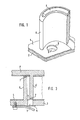
- the end plate 2 of one scroll member is formed with a hole 3 at its center portion for passage of the fluid.
- the hole 3 is generally formed by a simple and low-cost drilling or end milling operation, so that the hole is circular and is formed near the inner end portion .of spiral element 6 adjacent its inner wall, as shown in Fig. 1.
- Involute plate 4 disposed on the end plate 2 must be formed with matching hole 5 which is aligned with the hole 3 of end plate 2.
- the inner end portion of spiral element 6' sweeps over hole 3 (see Fig. 2).
- seal element 7 extends nearly to the inner end of spiral element 6'-a design which affords optimum sealing-seal element 7 will be quickly worn by abrasion against the edge of hole 3. Sealing is therefore usually compromised for the sake of seal longevity by using a seal element which terminates well short of the inner end of spiral element 6'.
- Volumetric efficiency can be maximized by delaying as much as possible communication of the central high pressure fluid space with the intermediate fluid pockets 8, 8', i.e., by maximizing the crank angle at which this communication occurs. Communication of the central high pressure fluid space with fluid pockets 8, 8' also can occur when the inner end portion of spiral element 6' is completely over hole 3, allowing high pressure fluid to leak back into pocket 8 behind the outer surface 6a of spiral element 6'. This can occur before the line contacts near the inner ends of spiral elements 6, 6' are broken.
- hole 3 is generally larger than it would be in other types of scroll apparatus. Spiral element 6' therefore encounters hole 3 earlier (i.e., at a smaller crank angle) than it would a smaller hole. Hence, leakage of high pressure fluid behind surface 6a of spiral element 6' occurs earlier than desired, resulting in a premature increase in the re-expansion volume and a loss of volumetric efficiency.
- FIG. 11 shows the relationship in a scroll type compressor of fluid pressure in an intermediate fluid pocket 8 to drive shaft crank angle, and shows that one compression cycle is completed in this case at a crank angle of 4 7 r.
- the compression cycle begins with the outer end of each spiral element 6, 6' in contact with the opposite spiral element, the suction stroke having finished.
- the state of fluid pressure in the fluid pockets is shown at point A in Fig. 11.
- the volume of the fluid pockets is reduced and fluid is compressed by the revolution of the orbiting scroll member until the crank angle reaches 2 ⁇ , which state is shown by point B in Fig. 11.
- a scroll type fluid displacement apparatus of the above- mentioned kind, which is characterized in that an involute anti-wear plate is provided within said first spiral wrap adjacent to said first end plate and that said fluid passage means comprises a hole through said first end plate and a notch through said involute plate overlying said hole, said notch having an elongated cross-section smaller than that of said hole, the longer dimension of said elongated cross section extending generally parallel to the adjacent portion of said first wrap.
- FIG. 4 illustrates a fluid displacement apparatus in accordance with the present invention, in particular a scroll type fluid displacement apparatus 1 according to one embodiment of the present invention.
- the apparatus 1 includes a housing 10 comprising a front end plate member 11 and a cup-shaped casing 12 which is disposed on an end surface of front end plate member 11.
- An opening 111 is formed in the center of front end plate member 11 for penetration or passage of a drive shaft 13.
- An annular projection 112 is formed on the rear end surface of front end plate member 11 which faces casing 12.
- An outer peripheral surface of annular projection 112 fits into an inner wall surface of the opening portion of casing 12.
- Casing 12 is fixed on the rear end surface of front end plate member 11 by a fastening means, for example bolts (not shown), so that the opening portion of casing 12 is covered by front end plate member 11.
- An O-ring member 14 is disposed between the outer peripheral surface of annular projection 112 and the inner wall surface of casing 12, to thereby effect a seal between the fitting or mating surfaces of front end plate member 11 and casing 12.
- Front end plate member 11 has an annular sleeve portion 15 projecting from the front end surface thereof for surrounding drive shaft 13 to define a shaft seal cavity.
- sleeve portion 15 is separate from front end plate member 11. Therefore, sleeve portion 15 is fixed to the front end surface of front end plate member 11 by fluid displacement apparatus which is simply a plurality of screws (not shown).
- An O-ring 16 is disposed between the end surface of front end plate member 11 and sleeve portion 15.
- sleeve portion 15 may be formed integral with front end plate member 11.
- Drive shaft 13 is rotatably supported by sleeve portion 15 through a bearing 17 disposed within the front end portion of sleeve portion 15.
- Drive shaft 13 is formed with a disk portion 131 at its inner end portion, and disk portion 131 is rotatably supported by front end plate member 11 through a bearing 18 dis - posed within opening 111 of front end plate member 11.
- a shaft seal assembly 19 is assembled on drive shaft 13 within the shaft seal cavity of sleeve portion 15.
- a pulley 20 is rotatably supported by sleeve portion 15 through a bearing 21 which is disposed on the outer surface of sleeve portion 15.
- An electromagnetic coil 22 is fixed on the outer surface of sleeve portion 15 by a support plate 221 and is received in an annular cavity of pulley 20.
- An armature plate 23 is elastically supported on the outer end portion of drive shaft 13 which extends from sleeve portion 15.
- a magnetic clutch comprising pulley 20, magnetic coil 22, and armature plate 23 is thereby formed.
- drive shaft 13 is driven by an external power source, for example the engine of an automobile, through force transmitting means, such as the magnetic clutch.
- a fixed scroll member 24, an orbiting scroll member 25, a cranktype driving mechanism 132 of orbiting scroll member 25, and a rotation preventing mechanism 133 of orbiting scroll member 25 are disposed in an inner chamber of cup-shaped casing 12.
- Typical driving and rotation preventing mechanisms are described in detail in the aforesaid EP-A-75053.
- Fixed scroll member 24 includes a circular end plate 241, a wrap means or spiral element 242 affixed to and extending from one side surface of end plate 241, and a plurality of internally threaded bosses 243 axially projecting from the end surface of end plate 241 opposite to the side thereof from which spiral element 242 extends.
- the end surface of each boss 243 is seated on the inner surface of end plate portion 121 of cup-shaped casing 12 and is fixed to end plate portion 121 by bolts 26.
- fixed scroll member 24 is fixedly disposed within casing 12.
- Circular end plate 241 of fixed scroll member 24 partitions the inner chamber of casing 12 into a discharge chamber 27 and a suction chamber 28 by a seal ring 29 disposed between the outer peripheral surface of end plate 241 and the inner wall of casing 12.
- Orbiting scroll member 25 is disposed within suction chamber 28 and also comprises a circular end plate 251 and a wrap means or spiral element 252 affixed to and extending from one side surface of end plate 251. Spiral element 252 and spiral element 242 of fixed scroll member 24 interfit at an angular offset of 180° and a predetermined radial offset. At least one pair of fluid pockets are thereby defined between spiral elements 242, 252. Orbiting scroll member 25 is connected to the driving mechanism and the rotation preventing mechanism. These two mechanisms effect orbital motion at a circular orbital radius Ro (not shown) by rotation of drive shaft 13, to thereby compress fluid passing through the compressor unit.
- Each spiral element 242, 252 is provided with a groove 30 formed in its axial end surface along the spiral curve. A seal element 31 is loosely fitted within groove 30. Sealing between the axial end surface of each spiral element and the inner end surface of the opposite end plate is effected by the seal element.
- Compressed fluid is discharged into discharge chamber 27 from the fluid pockets at the center of the spiral elements through a hole 244, which is formed through circular end plate 241 of fixed scroll member 24 at a position near the center of spiral element 242, past a valve 245", and is discharged therefrom through an outlet port 33 formed on casing 12 to an external fluid circuit, for example a cooling circuit.
- seal element 31 which is disposed in the axial end surface of each spiral element slides on the inner end surface of the opposite end plate and is urged against the end plate by compressed fluid.
- An involute anti- wear plate 34 (Fig. 5) is disposed between the axial end surface of each spiral element 242, 252 and the inner end surface of the opposite end plate 241, 251 for preventing wear of the end plate.
- Involute anti-wear plates 34 cover the area of the surfaces of end plates 241, 251 where spiral elements 242, 252 make axial contact during the orbital motion.
- the involute anti-wear plate 34 which is disposed on end plate 241 of fixed scroll member 24 is formed with a connecting notch or portion 341 adjacent discharge hole 244 of fixed scroll member 24, as shown in Fig. 4.
- a portion of hole 244 of fixed scroll member 24 is covered by part of involute plate 34, so that the open area of hole 244 is reduced and is moved closer to spiral element 242. Because of this, the area of the inner end portion of spiral element 252 which sweeps over hole 244 and contacts notch 341 of involute plate 34 is reduced. Therefore, seal element 31 disposed in spiral element 252 of orbiting scroll member 25 can extend closer to the inner end of spiral element 252, thereby improving axial sealing without premature seal wear. In addition, communication of the high pressure fluid pocket with the intermediate pressurized fluid pockets will be delayed, thereby reducing compression loss as shown by curve C'-D"-E" in Fig. 11, and improving volumetric efficiency.
- the portion of hole 244 which is located directly beneath the overlying portion of anti- wear plate 34 may be filled with a crescent-shaped plug 35 (Fig. 6b) whose curved face 351 is aligned with and matches the curved edge of notch 341.
- Plug 35 is preferably affixed in its proper position to the underside of anti- wear plate 34 so that, upon assembly of plate 34 with scroll member 24, plug 35 will be properly positioned and maintained in hole 244.
- Figs. 7 and 8 show an alternative embodiment of the present invention, wherein the placement of the hole formed through the end plate of the fixed scroll member is altered.
- FIGs. 7 and 8 show an alternative embodiment of the present invention, wherein the placement of the hole formed through the end plate of the fixed scroll member is altered.
- FIG. 7 show an alternative embodiment of the present invention, wherein the placement of the hole formed through the end plate of the fixed scroll member is altered.
- FIG. 7 show an alternative embodiment of the present invention, wherein the placement of the hole formed through the end plate of the fixed scroll member is altered.
- FIG. 7 and 8 show an alternative embodiment of the present invention, wherein the placement of the hole formed through the end plate of the fixed scroll member is altered.
- FIG. 7 and 8 show an alternative embodiment of the present invention, wherein the placement of the hole formed through the end plate of the fixed scroll member is altered.
- FIG. 7 and 8 show an alternative embodiment of the present invention, wherein the placement of the hole formed through the end plate of the fixed scroll member is altered.
- Figs. 9 and 10 show two different configurations of the inner end portion of fixed spiral element 242' of the embodiment of Figs. 7 and 8.
- the inner wall surface of fixed spiral element 242' has a portion 246' at the inner end portion thereof which protrudes inwardly beyond the normal involute spiral surface 248'.
- the curve of protruding portion 246' is close to or actually coincides with the orbital envelope generated by the center portion of spiral element 252' during its orbital motion.
- the protrusion 246' reduces the re-expansion volume, thereby improving volumetric efficiency, and strengthens the spiral element 242', which may be weakened somewhat by the formation of channel 245' therein.
- spiral element 242' having thickness t is formed by a numerically controlled milling machine.
- the radius R t of the working tool used for this machine is one half the pitch of the spiral element.
- the outer and inner wall surfaces of the spiral are, therefore, worked by this tool at the same time.
- the curve of protruding portion 246' is defined by an arc of orbital radius R o , which coincides with the orbital envelope generated by the orbiting scroll member, and by an arc having a radius R f- R o .
- the radius R t of the working tool is twice the radius of the involute generating circle.
- the curve of protruding portion 246' is defined by an arc of orbital radius R o , and an arc of radius Rt-Ro'
- hole 244 need not be circular.
- Hole 244 is preferably circular because it is easy and relatively inexpensive to simply drill or bore a circular hole through end plate 241. Using more complicated fabrication techniques, however, it is possible to form hole 244 as a crescent-shaped hole which matches the contour of notch 341. Hole 244 and notch 341 would then be fully aligned.
- hole 244' could be formed as a crescent-shaped hole which would match the contour of notch 341'.
Landscapes
- Engineering & Computer Science (AREA)
- Mechanical Engineering (AREA)
- General Engineering & Computer Science (AREA)
- Physics & Mathematics (AREA)
- Geometry (AREA)
- Rotary Pumps (AREA)
Claims (8)
Applications Claiming Priority (2)
| Application Number | Priority Date | Filing Date | Title |
|---|---|---|---|
| JP56033645A JPS6041237B2 (ja) | 1981-03-09 | 1981-03-09 | スクロ−ル型流体装置 |
| JP33645/81 | 1981-03-09 |
Publications (3)
| Publication Number | Publication Date |
|---|---|
| EP0061065A2 EP0061065A2 (fr) | 1982-09-29 |
| EP0061065A3 EP0061065A3 (en) | 1983-04-27 |
| EP0061065B1 true EP0061065B1 (fr) | 1985-01-23 |
Family
ID=12392175
Family Applications (1)
| Application Number | Title | Priority Date | Filing Date |
|---|---|---|---|
| EP82101876A Expired EP0061065B1 (fr) | 1981-03-09 | 1982-03-09 | Appareil à déplacement de fluide à volutes imbriquées |
Country Status (5)
| Country | Link |
|---|---|
| US (1) | US4498852A (fr) |
| EP (1) | EP0061065B1 (fr) |
| JP (1) | JPS6041237B2 (fr) |
| AU (1) | AU554442B2 (fr) |
| DE (1) | DE3261999D1 (fr) |
Cited By (1)
| Publication number | Priority date | Publication date | Assignee | Title |
|---|---|---|---|---|
| DE4204872A1 (de) * | 1991-02-19 | 1992-08-20 | Toyoda Automatic Loom Works | Spiralenkompressor |
Families Citing this family (33)
| Publication number | Priority date | Publication date | Assignee | Title |
|---|---|---|---|---|
| EP0075053B1 (fr) * | 1981-09-22 | 1986-12-17 | Sanden Corporation | Moyens anti-corrosion pour appareil de déplacement de fluide à volutes imbriquées |
| JPS5958187A (ja) * | 1982-09-26 | 1984-04-03 | Sanden Corp | スクロ−ル型圧縮機 |
| JPS5967595U (ja) * | 1982-10-29 | 1984-05-08 | 三菱重工業株式会社 | スクロ−ル型流体機械 |
| JPS59141190U (ja) * | 1983-03-14 | 1984-09-20 | サンデン株式会社 | スクロ−ル型コンプレツサの潤滑構造 |
| JPS59142484U (ja) * | 1983-03-15 | 1984-09-22 | サンデン株式会社 | スクロ−ル型流体装置における耐摩耗性板の構造 |
| JPS6079189A (ja) * | 1983-10-05 | 1985-05-04 | Hitachi Ltd | スクロ−ル流体機械 |
| CA1224971A (fr) * | 1983-12-05 | 1987-08-04 | Charles H. Tuckey | Pompe a engrenage pour carburant |
| JPS60249688A (ja) * | 1984-05-25 | 1985-12-10 | Mitsubishi Heavy Ind Ltd | 回転式流体機械 |
| GB2159882B (en) * | 1984-05-25 | 1988-02-10 | Mitsubishi Heavy Ind Ltd | Scroll-type rotary fluid machine |
| GB2167133B (en) * | 1984-11-19 | 1988-04-07 | Sanden Corp | Scroll-type rotary fluid-machine |
| US4781549A (en) * | 1985-09-30 | 1988-11-01 | Copeland Corporation | Modified wrap scroll-type machine |
| JPH0756274B2 (ja) * | 1987-03-20 | 1995-06-14 | サンデン株式会社 | スクロール式圧縮機 |
| JPH0254434U (fr) * | 1988-10-12 | 1990-04-19 | ||
| AU632332B2 (en) * | 1989-06-20 | 1992-12-24 | Sanden Corporation | Scroll type fluid displacement apparatus |
| US5105634A (en) * | 1990-10-29 | 1992-04-21 | American Standard Inc. | Scroll apparatus having a modified tip seal groove |
| JP2730818B2 (ja) * | 1991-12-16 | 1998-03-25 | 株式会社日立製作所 | スクロール形電動圧縮機 |
| US5222882A (en) * | 1992-02-20 | 1993-06-29 | Arthur D. Little, Inc. | Tip seal supporting structure for a scroll fluid device |
| JPH05321855A (ja) * | 1992-05-21 | 1993-12-07 | Toyota Autom Loom Works Ltd | スクロール型圧縮機におけるシール構造 |
| JP3036271B2 (ja) * | 1992-12-03 | 2000-04-24 | 株式会社豊田自動織機製作所 | スクロール型圧縮機 |
| US5474431A (en) * | 1993-11-16 | 1995-12-12 | Copeland Corporation | Scroll machine having discharge port inserts |
| TW381147B (en) * | 1994-07-22 | 2000-02-01 | Mitsubishi Electric Corp | Scroll compressor |
| JP3043979B2 (ja) * | 1995-10-20 | 2000-05-22 | サンデン株式会社 | スクロール型圧縮機用ボトムプレート |
| JPH109157A (ja) * | 1996-06-24 | 1998-01-13 | Sanden Corp | スクロール型圧縮機 |
| US5888057A (en) * | 1996-06-28 | 1999-03-30 | Sanden Corporation | Scroll-type refrigerant fluid compressor having a lubrication path through the orbiting scroll |
| JP2001032785A (ja) | 1999-07-16 | 2001-02-06 | Sanden Corp | スクロール型コンプレッサ |
| KR100437004B1 (ko) * | 2001-01-17 | 2004-07-02 | 미츠비시 쥬고교 가부시키가이샤 | 스크롤형 압축기 |
| JP2002213378A (ja) * | 2001-01-17 | 2002-07-31 | Mitsubishi Heavy Ind Ltd | スクロール型圧縮機 |
| JP2005291037A (ja) * | 2004-03-31 | 2005-10-20 | Nippon Soken Inc | 流体機械 |
| JP4999157B2 (ja) * | 2006-12-28 | 2012-08-15 | アネスト岩田株式会社 | 磁気カップリングを介して駆動源に結合した流体機械 |
| US8297958B2 (en) * | 2009-09-11 | 2012-10-30 | Bitzer Scroll, Inc. | Optimized discharge port for scroll compressor with tip seals |
| CN106438353B (zh) * | 2016-08-30 | 2018-10-09 | 安徽大富重工机械有限公司 | 涡旋压缩机及其涡旋盘、空调设备以及机动设备 |
| JP6485500B2 (ja) * | 2017-07-07 | 2019-03-20 | ダイキン工業株式会社 | スクロール圧縮機 |
| DE102022120681A1 (de) * | 2022-08-16 | 2024-02-22 | Bitzer Kühlmaschinenbau Gmbh | Scrollmaschine und Kälteanlage |
Citations (10)
| Publication number | Priority date | Publication date | Assignee | Title |
|---|---|---|---|---|
| DE13142C (de) * | F. SIEMENS in Dresden | Neuerungen an dem unter P. R. Nr. 6388 geschützten Kühlverfahren für Glaswaaren | ||
| AT106026B (de) * | 1926-01-22 | 1927-03-25 | Christine Latzelsperger | Vorrichtung zur lösbaren Befestigung von Haken im Mauerwerk. |
| US1755590A (en) * | 1925-07-22 | 1930-04-22 | United Carr Fastener Corp | Nut and screw fastening |
| US2049585A (en) * | 1932-05-23 | 1936-08-04 | Economy Fuse And Mfg Co | Electrical device |
| US2129949A (en) * | 1937-02-05 | 1938-09-13 | Albert E Tinnerman | Securing device |
| US2404169A (en) * | 1945-08-14 | 1946-07-16 | Norman L Gidden | Fastener |
| DE1233661B (de) * | 1960-01-22 | 1967-02-02 | N Jay Boots Doing Business As | Metallenes Einsatzteil zum Befestigen einer Schraube in Kunststoff |
| FR2165159A5 (fr) * | 1971-12-21 | 1973-08-03 | Talan Maryan | |
| FR2329885A1 (fr) * | 1975-10-28 | 1977-05-27 | Upat Max Langensiepen Kg | Element de fixation, notamment pour l'accrochage de conduites |
| CH600179A5 (en) * | 1976-04-14 | 1978-06-15 | Gusti C Huber | Dowel and washer fixing element |
Family Cites Families (10)
| Publication number | Priority date | Publication date | Assignee | Title |
|---|---|---|---|---|
| US904209A (en) * | 1907-09-11 | 1908-11-17 | Henry Clay Lyons | Pump. |
| GB220296A (en) * | 1923-08-08 | 1925-01-08 | Luigi Nordi | Improvements in or relating to fluid pumps and the like |
| US3313239A (en) * | 1965-06-30 | 1967-04-11 | Dover Corp | Vane-type pump |
| US3874827A (en) * | 1973-10-23 | 1975-04-01 | Niels O Young | Positive displacement scroll apparatus with axially radially compliant scroll member |
| US3994636A (en) * | 1975-03-24 | 1976-11-30 | Arthur D. Little, Inc. | Axial compliance means with radial sealing for scroll-type apparatus |
| JPS541360Y2 (fr) * | 1975-04-04 | 1979-01-22 | ||
| US4160629A (en) * | 1977-06-17 | 1979-07-10 | Arthur D. Little, Inc. | Liquid immersible scroll pump |
| JPS5596393A (en) * | 1979-01-19 | 1980-07-22 | Toshiba Corp | Drying method for sealed compressor |
| DE3017045A1 (de) * | 1979-05-14 | 1980-11-27 | Aginfor Ag | Kreiskolben-maschine sowie verwendung derselben |
| JPS6047443B2 (ja) * | 1980-10-27 | 1985-10-22 | 株式会社日立製作所 | スクロ−ル形流体機械 |
-
1981
- 1981-03-09 JP JP56033645A patent/JPS6041237B2/ja not_active Expired
-
1982
- 1982-03-09 EP EP82101876A patent/EP0061065B1/fr not_active Expired
- 1982-03-09 DE DE8282101876T patent/DE3261999D1/de not_active Expired
- 1982-03-09 AU AU81224/82A patent/AU554442B2/en not_active Expired
- 1982-03-09 US US06/356,497 patent/US4498852A/en not_active Expired - Lifetime
Patent Citations (10)
| Publication number | Priority date | Publication date | Assignee | Title |
|---|---|---|---|---|
| DE13142C (de) * | F. SIEMENS in Dresden | Neuerungen an dem unter P. R. Nr. 6388 geschützten Kühlverfahren für Glaswaaren | ||
| US1755590A (en) * | 1925-07-22 | 1930-04-22 | United Carr Fastener Corp | Nut and screw fastening |
| AT106026B (de) * | 1926-01-22 | 1927-03-25 | Christine Latzelsperger | Vorrichtung zur lösbaren Befestigung von Haken im Mauerwerk. |
| US2049585A (en) * | 1932-05-23 | 1936-08-04 | Economy Fuse And Mfg Co | Electrical device |
| US2129949A (en) * | 1937-02-05 | 1938-09-13 | Albert E Tinnerman | Securing device |
| US2404169A (en) * | 1945-08-14 | 1946-07-16 | Norman L Gidden | Fastener |
| DE1233661B (de) * | 1960-01-22 | 1967-02-02 | N Jay Boots Doing Business As | Metallenes Einsatzteil zum Befestigen einer Schraube in Kunststoff |
| FR2165159A5 (fr) * | 1971-12-21 | 1973-08-03 | Talan Maryan | |
| FR2329885A1 (fr) * | 1975-10-28 | 1977-05-27 | Upat Max Langensiepen Kg | Element de fixation, notamment pour l'accrochage de conduites |
| CH600179A5 (en) * | 1976-04-14 | 1978-06-15 | Gusti C Huber | Dowel and washer fixing element |
Cited By (1)
| Publication number | Priority date | Publication date | Assignee | Title |
|---|---|---|---|---|
| DE4204872A1 (de) * | 1991-02-19 | 1992-08-20 | Toyoda Automatic Loom Works | Spiralenkompressor |
Also Published As
| Publication number | Publication date |
|---|---|
| JPS57148088A (en) | 1982-09-13 |
| EP0061065A3 (en) | 1983-04-27 |
| AU554442B2 (en) | 1986-08-21 |
| JPS6041237B2 (ja) | 1985-09-14 |
| US4498852A (en) | 1985-02-12 |
| AU8122482A (en) | 1982-09-16 |
| EP0061065A2 (fr) | 1982-09-29 |
| DE3261999D1 (en) | 1985-03-07 |
Similar Documents
| Publication | Publication Date | Title |
|---|---|---|
| US4498852A (en) | Scroll type fluid displacement apparatus with improved end plate fluid passage means | |
| US6299423B1 (en) | Scroll machine with discharge valve | |
| US4561832A (en) | Lubricating mechanism for a scroll-type fluid displacement apparatus | |
| US4722676A (en) | Axial sealing mechanism for scroll type fluid displacement apparatus | |
| EP0077214B1 (fr) | Compresseur à volutes imbriquées avec rendement élevé | |
| EP0326189B1 (fr) | Compresseur à volutes imbriquées avec mécanisme de réglage du déplacement | |
| US4437820A (en) | Scroll type fluid compressor unit with axial end surface sealing means | |
| US4627800A (en) | Scroll type fluid displacement compressor with spiral wrap elements of varying thickness | |
| US20070110604A1 (en) | Scroll machine | |
| US5302095A (en) | Orbiting rotary compressor with orbiting piston axial and radial compliance | |
| US4627799A (en) | Axial sealing mechanism for a scroll type fluid displacement apparatus | |
| US4645436A (en) | Scroll type fluid displacement apparatus with improved anti-wear device | |
| US4540355A (en) | Axial sealing device for a scroll-type fluid displacement apparatus | |
| EP0106287B1 (fr) | Appareil à volutes pour déplacer un fluide | |
| US20200102956A1 (en) | Motor operated compressor | |
| US4571163A (en) | Axial clearance adjustment mechanism for scroll-type fluid displacement apparatus | |
| AU615361B2 (en) | Scroll member for scroll type fluid displacement apparatus | |
| EP0065261B1 (fr) | Joint d'étanchéité axial pour une machine à déplacement à volutes imbriquées | |
| US5582511A (en) | Scroll machine having discharge port inserts | |
| EP0743454B1 (fr) | Appareil de déplacement de fluides à spirales | |
| CA1311455C (fr) | Mecanisme d'etancheite axial pour compresseur a volute | |
| US4956058A (en) | Scroll type fluid displacement apparatus with surface treated spiral element | |
| EP3690247A1 (fr) | Compresseur à spirales | |
| EP0468238B1 (fr) | Compresseur à spirales avec mécanisme de déplacement variable | |
| KR100608859B1 (ko) | 스크롤압축기의 역류방지장치 |
Legal Events
| Date | Code | Title | Description |
|---|---|---|---|
| PUAI | Public reference made under article 153(3) epc to a published international application that has entered the european phase |
Free format text: ORIGINAL CODE: 0009012 |
|
| AK | Designated contracting states |
Designated state(s): DE FR GB IT SE |
|
| PUAL | Search report despatched |
Free format text: ORIGINAL CODE: 0009013 |
|
| AK | Designated contracting states |
Designated state(s): DE FR GB IT SE |
|
| 17P | Request for examination filed |
Effective date: 19830304 |
|
| RAP1 | Party data changed (applicant data changed or rights of an application transferred) |
Owner name: SANDEN CORPORATION |
|
| ITF | It: translation for a ep patent filed | ||
| GRAA | (expected) grant |
Free format text: ORIGINAL CODE: 0009210 |
|
| AK | Designated contracting states |
Designated state(s): DE FR GB IT SE |
|
| REF | Corresponds to: |
Ref document number: 3261999 Country of ref document: DE Date of ref document: 19850307 |
|
| ET | Fr: translation filed | ||
| PLBE | No opposition filed within time limit |
Free format text: ORIGINAL CODE: 0009261 |
|
| STAA | Information on the status of an ep patent application or granted ep patent |
Free format text: STATUS: NO OPPOSITION FILED WITHIN TIME LIMIT |
|
| 26N | No opposition filed | ||
| ITTA | It: last paid annual fee | ||
| EAL | Se: european patent in force in sweden |
Ref document number: 82101876.9 |
|
| PGFP | Annual fee paid to national office [announced via postgrant information from national office to epo] |
Ref country code: SE Payment date: 20010306 Year of fee payment: 20 Ref country code: DE Payment date: 20010306 Year of fee payment: 20 |
|
| PGFP | Annual fee paid to national office [announced via postgrant information from national office to epo] |
Ref country code: GB Payment date: 20010307 Year of fee payment: 20 |
|
| PGFP | Annual fee paid to national office [announced via postgrant information from national office to epo] |
Ref country code: FR Payment date: 20010313 Year of fee payment: 20 |
|
| REG | Reference to a national code |
Ref country code: GB Ref legal event code: IF02 |
|
| PG25 | Lapsed in a contracting state [announced via postgrant information from national office to epo] |
Ref country code: GB Free format text: LAPSE BECAUSE OF EXPIRATION OF PROTECTION Effective date: 20020308 |
|
| REG | Reference to a national code |
Ref country code: GB Ref legal event code: PE20 Effective date: 20020308 |
|
| EUG | Se: european patent has lapsed |
Ref document number: 82101876.9 |