EP0062493B1 - Bandpassfilter mit mehrschichtiger Spulenstruktur - Google Patents
Bandpassfilter mit mehrschichtiger Spulenstruktur Download PDFInfo
- Publication number
- EP0062493B1 EP0062493B1 EP82301693A EP82301693A EP0062493B1 EP 0062493 B1 EP0062493 B1 EP 0062493B1 EP 82301693 A EP82301693 A EP 82301693A EP 82301693 A EP82301693 A EP 82301693A EP 0062493 B1 EP0062493 B1 EP 0062493B1
- Authority
- EP
- European Patent Office
- Prior art keywords
- coil
- resonators
- band
- circuit
- pass filter
- Prior art date
- Legal status (The legal status is an assumption and is not a legal conclusion. Google has not performed a legal analysis and makes no representation as to the accuracy of the status listed.)
- Expired
Links
- 230000008878 coupling Effects 0.000 claims description 22
- 238000010168 coupling process Methods 0.000 claims description 22
- 238000005859 coupling reaction Methods 0.000 claims description 22
- 239000003990 capacitor Substances 0.000 claims description 13
- 239000000758 substrate Substances 0.000 description 8
- 239000004020 conductor Substances 0.000 description 7
- 229920003023 plastic Polymers 0.000 description 3
- 239000004033 plastic Substances 0.000 description 3
- 229910052782 aluminium Inorganic materials 0.000 description 2
- XAGFODPZIPBFFR-UHFFFAOYSA-N aluminium Chemical compound [Al] XAGFODPZIPBFFR-UHFFFAOYSA-N 0.000 description 2
- 238000004519 manufacturing process Methods 0.000 description 2
- 229910052751 metal Inorganic materials 0.000 description 2
- 239000002184 metal Substances 0.000 description 2
- 229920002635 polyurethane Polymers 0.000 description 2
- 239000004814 polyurethane Substances 0.000 description 2
- 238000004804 winding Methods 0.000 description 2
- 239000004698 Polyethylene Substances 0.000 description 1
- 150000001875 compounds Chemical class 0.000 description 1
- 238000010586 diagram Methods 0.000 description 1
- 238000003780 insertion Methods 0.000 description 1
- 230000037431 insertion Effects 0.000 description 1
- 239000000463 material Substances 0.000 description 1
- 230000004048 modification Effects 0.000 description 1
- 238000012986 modification Methods 0.000 description 1
- -1 polyethylene Polymers 0.000 description 1
- 229920000573 polyethylene Polymers 0.000 description 1
Images



Classifications
-
- H—ELECTRICITY
- H03—ELECTRONIC CIRCUITRY
- H03H—IMPEDANCE NETWORKS, e.g. RESONANT CIRCUITS; RESONATORS
- H03H7/00—Multiple-port networks comprising only passive electrical elements as network components
- H03H7/01—Frequency selective two-port networks
- H03H7/09—Filters comprising mutual inductance
-
- H—ELECTRICITY
- H01—ELECTRIC ELEMENTS
- H01P—WAVEGUIDES; RESONATORS, LINES, OR OTHER DEVICES OF THE WAVEGUIDE TYPE
- H01P7/00—Resonators of the waveguide type
- H01P7/005—Helical resonators; Spiral resonators
Definitions
- the present invention relates to a band-pass filter and, more particularly, such a filter comprising at least two quarter-wavelength resonators each having one end thereof open-circuited and the other end thereof short-circuited, and at least two parallel circuit resonators each having a coil and a capacitor.
- a band-pass filter disclosed in U.S.-A-4 210 884, comprises within a shielded housing a plurality of juxtaposed quarter-wavelength resonators each comprised of a cylindrical bobbin on which a coil is wound.
- Each resonator further comprises a capacitor to form parallel resonance circuits with the coils, one end of each of the parallel-circuit resonators being connected at one end of the other parallel-circuit resonator at a circuit point outside of the housing.
- First and second auxiliary coils are inductively coupled with the coils of the parallel-circuit resonators and one end of each of the auxiliary coils are coupled together to the circuit point.
- One object of the present invention is to eliminate or minimise the problems and shortcomings inherent in conventional band-pass filters.
- a band-pass filter comprising a shielded housing, at least two quarter-wavelength resonators mounted in the housing and each having one end connected to the housing and the other end open-circuited, at least two other resonators mounted between the two quarter-wavelength resonators to provide interstage coupling therewith, a shield separating the said two other resonators, and input and output coils respectively coupled with the quarter-wavelength resonators, wherein each resonator comprises a bobbin carrying a coil and each of the said other resonators comprises a capacitor to form a parallel resonance circuit with the coil, one end of one of the parallel circuit resonators being connected to one end of the other parallel circuit resonator at a circuit point outside the housing, and wherein first and second auxiliary coils inductively coupled with the coils of the parallel circuit resonators each have one end thereof connected to one end of the other auxiliary coil and the other end thereof coupled to the circuit point, characterised in that the bobbin
- Fig. 1 is an illustration of a cross-sectional view. of a prior art band-pass filter the schematic details of which are shown in Fig. 2.
- Fig. 1 illustrated each at 1, 1', 1", and 1 "' are quarter-wavelength resonators comprising an insulative cylindrical bobbin 2 which is formed of a plastic material and has a polyethylene insulated conductor helically coiled therearound.
- the resonators are mounted in juxtaposition on an insulating substrate 3 so that one end of the coil of each resonator is open-circuited with the other end of the coil being coupled to ground by an earth terminal provided on the substrate 3.
- Illustrated at 4 is a shielded metal housing formed typically of aluminum, the metal housing comprising a plurality of shielding plates or separating walls 6 each having an opening 5 through the resonators 1, 1', 1" and 1"' are coupled adjustably.
- a pair of input and output coupling coils 7 and 7' are provided adjacent to the resonators 1 and 1 "', respectively.
- Illustrated at 8 is a magnetic core provided for the purpose of adjusting the resonant frequency of each quarter-wavelength resonator.
- the frequency response characteristic of the prior art filter is indicated by a broken line curve in Fig. 7. As illustrated the response characteristic has a gradually varying decay on each end of the passband.
- the length of conductors is exclusively determined by the resonant frequency of the filter, that is, the quarter-wavelength, as a result of which while the filter could successfully have a reduced height the diameter of its coils would inevitably increase, and vice versa. Therefore, it has been recognized thatthe prior art band-passfilter allows no compact design.
- a still further shortcoming inherent in the prior art band-pass filter is that while the magnetic core 8 possesses a certain amount of negative temperature coefficient, the amount of this negative coefficient is not sufficient to cover the full range of temperatures for temperature compensation purposes.
- the present invention is intended to overcome the above-discussed disadvantages and shortcomings of the prior art band-pass filter, while at the same time improving the sharpness of frequency cut-off characteristics and the temperature compensating performance, and in addition the allowability of compact design.
- the following is a description of an embodiment of the present invention which will proceed with reference to Figs. 3 to 11.
- Fig. 3 is a cross-sectional view of the band-pass filter of the invention and Fig. 4 an equivalent circuit of the filter. Illustrated at 9a and 9b are quarter-wavelength resonators comprised of plastic moulded bobbins 11 a and 11 b each having a plurality of axially spaced apart annular fins 10. Between adjacent fins 10 the bobbins 11 a and 11 b are wound by coil portions 11 a' and 11 b' of multi- layered coil structures. Each of the coil portions has a few turns or several tens of turns of a polyurethane coated conductor.
- the quarter-wavelength resonators 9a and 9b are juxtaposed on common insulative substrate 12 so that one end of each multilayered coil structures is open-circuited and the other end is short-circuited by coupling to a ground terminal mounted on the insulative substrate 12.
- Illustrated at 13 is a shielded aluminum housing which is coupled to ground and comprises first and second chambers separated by a shielding plate 16, the first and second chambers being further divided with shielding plate 15a and 15b having respective coupling windows 14a, 14b into outer chamber sections 17a, 17b in which the quarter-wavelength resonators 9a and 9b are respectively disposed and inner chamber sections 17c and 17d.
- the quarter-wave resonators 9a, 9b are arranged to inductively couple with input and output coupling coils 19a and 19b which are mounted on the bobbins of the quarter-wave resonators 9a and 9b, respectively.
- Paralle[-circuit resonators 9c and 9d are each formed by plastic moulded bobbins 11c and 11d having a plurality of vertically spaced apart annular fins 10.
- Amultilayered coil structure 11c' having a pair of coil portions and a multilayered coil structure 11d' having a pair of coil portions are mounted between adjacent fins 10 of bobbins 11c and 11d respectively, the ends of these coils being coupled respectively to terminals mounted below the insulative substrate 12 for connection to an external circuit.
- Coils 11c' and 11d' are each formed of a few turns of polyurethane coated conductor.
- capacitors 21c and 21d which are respectively coupled to the coils 11c' and 11 d' to constitute parallel resonance circuits.
- Auxiliary coils 22c and 22d of a few turns are wound on the bobbins 11c and 11d to inductively couple with the coils 11c' and 11 d', respectively.
- One end of the auxiliary coil 22c is coupled to the ground terminal on substrate 12 and the other end of which is coupled to the coil 20c and capacitor 21c and taken to the outside for coupling with the other auxiliary coil 22d.
- one end of the auxiliary coil 22d is coupled to the ground terminal with the other end being coupled to the coil 11d' and capacitor 21 d and taken to the outside where it is coupled to the auxiliary coil 22c.
- Illustrated at 23a, 23b, 23c, 23d are magnetic cores which are threadably engaged with the internally threaded walls of the bobbins 11 a, 11 b, 11c, 11d, respectively, for making adjustment on the respective resonant frequencies of the resonators 9a, 9b, 9c and 9d by means of a screwdriver.
- the coils 20c and 20d have a small amount of positive values of temperature coefficient which can be compensated for by having a small amount of negative coefficient in the capacitors 21c and 21d.
- the amount of distributed capacitances can be increased significantly, whereby the inductance of the quarter-wave resonators 9a and 9b and hence the number of turns of their coils can be reduced.
- capacitors 21c and 21d which form part of the parallel circuit resonators 9c, 9d permits the coils 20c and 20d to have a reduced number of turn in comparison with the prior art arrangement and as a result the bobbins 9c and 9d can be reduced in diameter, whereby the total dimensions of the band-pass filter are minimized.
- the present invention permits the use of a conductor of a relatively large gauge which produces sharpness in the selectivity.
- the size of coupling windows 14a and 14b can be appropriately dimensioned to obtain a desired amount of interstage coupling between adjacent resonators so that the passband of the filter can be controlled to obtain a desired bandwidth. This feature is of significant advantage for practical purposes.
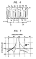
- Figs. 5 and 6 are illustrations of another embodiment of the present invention.
- the embodiment of Fig. 5 differs from the previous embodiment in that it includes a coil 24 interposed between the coil 19 and a circuit junction between auxiliary coils 22c and 22d and mounted outside of the shielded housing 13.
- the inductance of the coil 24 and capacitive coupling between the quarter-wave resonator 9a and the coil 11c' of parallel-circuit resonator 9c form a parallel resonant trap circuit which serves to give rise to a high value of attenuation at a point slightly below the lowermost frequency of the passband thereby significantly improving the sharpness of the passband characteristic at the lower cut-off frequency as depicted by a dot-and-dash line curve in Fig. 7.
- the invention provides an advantage in that it allows a wide range of variations in the bandwidth of the filter without having to alter the gauge of the conductors and the dimensions of the coupling windows 14 of the shielded housing 13. Specifically, the bandwidth coils of the resonators 9a and 9b or the ratio of the number of such coils to the number of turns of wire wound on each of such coils. Otherwise, the opening of the coupling windows 14 would have to be increased.
- a further embodiment of the present invention shown in Fig. 6 differs from the Fig. 5 embodiment in that it further includes a coil 25 connected between the output coil 19b and a circuit junction between the auxiliary coils 22a and 22b.
- the insertion of coils 24 and 25 introduces attenuations on points slightly lower and higher than the passband as indicated by a two-dot- dash line curve in Fig. 7.
- the separating wall 15c could be formed with a coupling window which would serve to add an extra amount of capacitive coupling between coils 11c' and 11d' with the result that a gradual decay will occur at the high frequency cut-off end of the passband. This affords an optional feature of the invention with which the cut-off characteristic of the high frequency end could be altered to meet specific requirements.
- Winding operation during manufacture could be facilitated by separating the insulative substrate into parts with which the finned bobbins 11a, 11b, 11c, 11d are integrally formed respectively to permit each of such integrated bobbin structures to be coiled separately with respective windings.
- This arrangement would eliminate the use of a compound or wax for fixing the conductors, thereby significantly improving the moisture resistant properties of the coils.
- the coils 24 and 25 could also be mounted on the bobbins 9 in a manner identical to that with which the auxiliary coils 22c, 22d are mounted.
- the band-pass filter constructed in a manner as taught in the present invention has significantly improved cut-off characteristics and is kept to a minimum which can be advantageously employed in television receivers to serve as a video intermediate frequency filter as illustrated in Fig. 8.
- Fig. 8 is a schematic illustration of a video intermediate frequency filter of a television receiver.
- the VIF comprises an audio trap circuit 26 used for trapping signals on an adjacent television channel.
- This trap circuit is formed by capacitors C" C 2 , C 3 , coils L" L 2 , and a resistor R all of which are connected to form a bridged T network.
- the coil L 2 is a peaking coil which serves to improve the sharpness of the higher cut-off frequency of the trap circuit 26.
- the output of the audio trap circuit 26 is coupled to an input of a band-pass filter of the present invention indicated by numerals identical to those used in Figs. 3 to 6 preceded by the figure number.
- the output of the audio trap circuit 26 is applied to the input coil 819a and also to coil 824 which is coupled to the junction between auxiliary coils 822c and 822d.
- the inductance of coil 824 and capacitive coupling between coils 819a, 811 a', and 822c constitute a parallel resonance circuit which produces an attenuation in a lower cut-off frequency point of the passband to act as a video trap circuit 28 for trapping signals on the adjacent television channel.
- This parallel resonance circuit also forms a capacitively coupled trap circuit with the shielded housing 13 giving rise to an attenuation in a higher frequency point of the passband.
- the junction between the coils 824 and 822c serves as an output terminal of the video trap circuit 28 and is coupled to the coil 822d.
- Coil 822c, parallel circuit resonator 809d (capacitor 821 and coil 820d), quarter-wave resonator 809b and output coil 819b constitute a band-pass filter 27.
- the VIF of Fig. 8 thus provides a high attenuation on either cut-off frequency point.
- the difference in attenuation between the video trapping frequency of the adjacent chanel and the foldover frequency is significantly reduced on the lower cut-off frequency.
- the video trap of the adjacent channel is broadened so that adjustment of trapping frequency can be relaxed to advantage for manufacture.
- the VIF of Fig. 8 can be alternatively modified as shown in Fig. 9 which differs from the Fig. 8 embodiment in that the coil 824 is connected to the output coil 819b.
Landscapes
- Control Of Motors That Do Not Use Commutators (AREA)
- Filters And Equalizers (AREA)
Claims (8)
Applications Claiming Priority (4)
| Application Number | Priority Date | Filing Date | Title |
|---|---|---|---|
| JP56053415A JPS57168503A (en) | 1981-04-08 | 1981-04-08 | Band pass filter |
| JP53415/81 | 1981-04-08 | ||
| JP56198089A JPS5899004A (ja) | 1981-12-08 | 1981-12-08 | 映像中間周波フイルタ− |
| JP198089/81 | 1981-12-08 |
Publications (3)
| Publication Number | Publication Date |
|---|---|
| EP0062493A2 EP0062493A2 (de) | 1982-10-13 |
| EP0062493A3 EP0062493A3 (en) | 1983-10-26 |
| EP0062493B1 true EP0062493B1 (de) | 1987-03-04 |
Family
ID=26394124
Family Applications (1)
| Application Number | Title | Priority Date | Filing Date |
|---|---|---|---|
| EP82301693A Expired EP0062493B1 (de) | 1981-04-08 | 1982-03-31 | Bandpassfilter mit mehrschichtiger Spulenstruktur |
Country Status (3)
| Country | Link |
|---|---|
| US (1) | US4422059A (de) |
| EP (1) | EP0062493B1 (de) |
| DE (1) | DE3275618D1 (de) |
Families Citing this family (7)
| Publication number | Priority date | Publication date | Assignee | Title |
|---|---|---|---|---|
| US4682131A (en) * | 1985-06-07 | 1987-07-21 | Motorola Inc. | High-Q RF filter with printed circuit board mounting temperature compensated and impedance matched helical resonators |
| GB2209259A (en) * | 1987-05-06 | 1989-05-04 | Victor John Gordon Gale | A mixed filter circuit |
| US6937115B2 (en) | 2002-02-25 | 2005-08-30 | Massachusetts Institute Of Technology | Filter having parasitic inductance cancellation |
| US7589605B2 (en) * | 2006-02-15 | 2009-09-15 | Massachusetts Institute Of Technology | Method and apparatus to provide compensation for parasitic inductance of multiple capacitors |
| US9441439B2 (en) * | 2012-08-08 | 2016-09-13 | Schlumberger Technology Corporation | Rotary actuated cutter module system and methodology |
| EE01394U1 (et) * | 2016-10-13 | 2017-04-17 | Tarmin Eesti Trade Oü | Elektromagnetiline resonaator |
| JP2018078515A (ja) * | 2016-11-11 | 2018-05-17 | 東京エレクトロン株式会社 | フィルタ装置及びプラズマ処理装置 |
Family Cites Families (4)
| Publication number | Priority date | Publication date | Assignee | Title |
|---|---|---|---|---|
| US3247475A (en) * | 1963-09-06 | 1966-04-19 | Motorola Inc | Helical resonator with variable capacitor having fixed plate which also functions as inductance |
| US3691487A (en) * | 1970-04-24 | 1972-09-12 | Toko Inc | Helical resonator type filter |
| US3970972A (en) * | 1975-05-12 | 1976-07-20 | Northern Electric Company Limited | Shock resistant, temperature compensated helical resonator |
| GB1602770A (en) * | 1977-06-03 | 1981-11-18 | Matsushita Electric Industrial Co Ltd | Band pass filter |
-
1982
- 1982-03-31 DE DE8282301693T patent/DE3275618D1/de not_active Expired
- 1982-03-31 US US06/363,998 patent/US4422059A/en not_active Expired - Lifetime
- 1982-03-31 EP EP82301693A patent/EP0062493B1/de not_active Expired
Also Published As
| Publication number | Publication date |
|---|---|
| US4422059A (en) | 1983-12-20 |
| EP0062493A3 (en) | 1983-10-26 |
| DE3275618D1 (en) | 1987-04-09 |
| EP0062493A2 (de) | 1982-10-13 |
Similar Documents
| Publication | Publication Date | Title |
|---|---|---|
| US4255729A (en) | High frequency filter | |
| KR920010600B1 (ko) | 대역저지 기능을 갖춘 필터 및 송수절환기 | |
| EP0520641B1 (de) | Abstimmbare Resonatoranordnung | |
| US4456895A (en) | Band selectable tunable bandpass filter | |
| US3516030A (en) | Dual cavity bandpass filter | |
| US4182997A (en) | Band-pass/band-stop filter for telecommunication system | |
| US4210884A (en) | Helical resonator band pass filter with novel coupling means | |
| US4422059A (en) | Band-pass filter having multilayered coil structures | |
| JPS6277703A (ja) | 誘電体フイルタ | |
| US2703389A (en) | Time-delay network | |
| US5418509A (en) | High frequency comb-like filter | |
| US4730173A (en) | Asymmetrical trap comprising coaxial resonators, reactance elements, and transmission line elements | |
| US3538463A (en) | Microwave filter | |
| US2704829A (en) | Delay line | |
| US3487339A (en) | Intermediate frequency coupling network having a sharply tuned sound carrier cancellation trap inductively coupled to the input circuit | |
| EP1191626B1 (de) | Resonatorfilter | |
| JPS6322641B2 (de) | ||
| US2868983A (en) | Ultra-high frequency structures | |
| US2141254A (en) | High-frequency coupling device | |
| JPS6224962Y2 (de) | ||
| JPS6244566Y2 (de) | ||
| SU1626333A1 (ru) | Электромагнитна лини задержки | |
| JPS6029231Y2 (ja) | 濾波器 | |
| JPS5952841B2 (ja) | 誘電体線路形フイルタ | |
| JP3118411B2 (ja) | 同調回路 |
Legal Events
| Date | Code | Title | Description |
|---|---|---|---|
| PUAI | Public reference made under article 153(3) epc to a published international application that has entered the european phase |
Free format text: ORIGINAL CODE: 0009012 |
|
| AK | Designated contracting states |
Designated state(s): DE GB |
|
| PUAL | Search report despatched |
Free format text: ORIGINAL CODE: 0009013 |
|
| AK | Designated contracting states |
Designated state(s): DE GB |
|
| 17P | Request for examination filed |
Effective date: 19840308 |
|
| GRAA | (expected) grant |
Free format text: ORIGINAL CODE: 0009210 |
|
| AK | Designated contracting states |
Kind code of ref document: B1 Designated state(s): DE GB |
|
| REF | Corresponds to: |
Ref document number: 3275618 Country of ref document: DE Date of ref document: 19870409 |
|
| PLBE | No opposition filed within time limit |
Free format text: ORIGINAL CODE: 0009261 |
|
| STAA | Information on the status of an ep patent application or granted ep patent |
Free format text: STATUS: NO OPPOSITION FILED WITHIN TIME LIMIT |
|
| 26N | No opposition filed | ||
| PGFP | Annual fee paid to national office [announced via postgrant information from national office to epo] |
Ref country code: GB Payment date: 19950321 Year of fee payment: 14 |
|
| PGFP | Annual fee paid to national office [announced via postgrant information from national office to epo] |
Ref country code: DE Payment date: 19950322 Year of fee payment: 14 |
|
| PG25 | Lapsed in a contracting state [announced via postgrant information from national office to epo] |
Ref country code: GB Effective date: 19960331 |
|
| GBPC | Gb: european patent ceased through non-payment of renewal fee |
Effective date: 19960331 |
|
| PG25 | Lapsed in a contracting state [announced via postgrant information from national office to epo] |
Ref country code: DE Effective date: 19961203 |