EP0062705A1 - Regelungsvorrichtung für die Zu- und Abführung von Drucköl in zum Antrieb von Schwenkarmen an Arbeitsmaschinen dienenden ölhydraulischen Hubmitteln - Google Patents
Regelungsvorrichtung für die Zu- und Abführung von Drucköl in zum Antrieb von Schwenkarmen an Arbeitsmaschinen dienenden ölhydraulischen Hubmitteln Download PDFInfo
- Publication number
- EP0062705A1 EP0062705A1 EP81110138A EP81110138A EP0062705A1 EP 0062705 A1 EP0062705 A1 EP 0062705A1 EP 81110138 A EP81110138 A EP 81110138A EP 81110138 A EP81110138 A EP 81110138A EP 0062705 A1 EP0062705 A1 EP 0062705A1
- Authority
- EP
- European Patent Office
- Prior art keywords
- chamber
- oil
- cylinder
- chambers
- supply
- Prior art date
- Legal status (The legal status is an assumption and is not a legal conclusion. Google has not performed a legal analysis and makes no representation as to the accuracy of the status listed.)
- Withdrawn
Links
Images

Classifications
-
- F—MECHANICAL ENGINEERING; LIGHTING; HEATING; WEAPONS; BLASTING
- F15—FLUID-PRESSURE ACTUATORS; HYDRAULICS OR PNEUMATICS IN GENERAL
- F15B—SYSTEMS ACTING BY MEANS OF FLUIDS IN GENERAL; FLUID-PRESSURE ACTUATORS, e.g. SERVOMOTORS; DETAILS OF FLUID-PRESSURE SYSTEMS, NOT OTHERWISE PROVIDED FOR
- F15B13/00—Details of servomotor systems ; Valves for servomotor systems
- F15B13/02—Fluid distribution or supply devices characterised by their adaptation to the control of servomotors
Definitions
- the mentioned invention relates to a device for adjusting the supply and flow of oil under pressure in the oleodynamic jacks used to actuate the articulated arms of operating machines. It is particularly indicated to be applied on the articulated arms of concrete pumps, but could be used on any other operating machine with articulated arms with oleodynamic operation.
- Oleodynamic jacks work with a very high operating pressure and with variable and harsh loading conditions, and therefore very safe control devices are required, with protections against overpressures which could occur in the event of an overload of the articulated arm. and which could cause the tubes to explode and the uncontrollable fall of the arm itself.
- the devices currently used are fitted with a calibrated valve which allows controlled oil flow into the tank when the operating pressure exceeds the maximum expected value. But the surfaces of the piston which is present on the two opposite chambers of the cylinder are diversified by the presence of the rod and therefore the valve is calibrated to a value intermediate - chosen from among the best - for both directions of actuation.
- the device mentioned makes it possible to eliminate these drawbacks and also uses two bodies applied directly to the two ends of the cylinder, without using tubes which encumber and can cause losses. Another advantage is the possibility of using a dispenser of the closed center type, which guarantees a further safety in the event of valve rupture, something impossible with other applications.
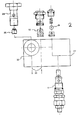
- n ° 1 indicates the piston which slides in the cylinder 2 and whose rod 3 is connected to the articulated arm 4.
- the n ° 5 and 5 ' indicate the two equal control elements applied directly to the two ends of the cylinder 2.
- n ° 6 is the distributor, ty eg with closed center, ie with the central hydraulic circuits interrupted when the relative enabling control is not actuated.
- the pump is at No. 7 and the oil tank at No. 8; at No. 9 is the filter inserted in the return duct.
- valves 10 and 10 block the passage of the oil when we want to keep the arm in the desired position, when we want to lower the arm, we send, using the distributor 6, pressurized oil in the conduit 11, oil which feeds the chamber 12 of the cylinder.
- the valves 10 and 13 open, being traversed by the oil in the direct direction.
- the opening of the valve 10 ′, to allow the oil to flow into the chamber 14 of the cylinder, is obtained by the pressurized oil which passes through the pilot duct 15 ′ of the valve itself.
- the constricted conduit 16 'allows controlled passage of the oil, since the valve 13' is closed. The operation is similar when we want to raise the arm and we send the oil under pressure in the conduit 11 'to supply the chamber 140
- the calibrated valve 17 ' opens and the oil leaves the chamber 14 passing through the throttled conduit 16', which slows down the speed, offering a subsequent safety : indeed the choke is immediately at the outlet of the cylinder, so as to slow down the outlet of the oil even if there are anomalies in the regulator.
- Oil passes through 17 'valve and arrives, through the conduits 18 ′ and 18, at the valve 19.
- the valves 19 and 13 open, being traversed in the direct direction and allow the entry of the oil into the opposite chamber 12, preventing cavitation or partial emptying.
- the quantity of oil arriving from chamber 14 is insufficient to completely fill chamber 12, since chamber 14 has a smaller volume due to the presence of the rod 3.
- the calibrated valve 20 which aims to create a counterpressure in the circuit constantly traversed by the oil, constituted by the supply conduit 22 and that of return 21. In this way the quantity of oil missing for filling the chamber 12 is diverted upstream of the valve 20 and through the conduit 23.
- the derived oil arrives at the chamber 12 via the conduits 24 and 18.
- At No. 25 there is a conduit which carries the oil with similar devices applied to other cylinders which are controlled by the distributor 6 and the pump 7.
- the reducing valve 17 opens, because of an overload when the chamber 12 is fed, the oil leaves the chamber through the throttled conduit 16 and the valve 17 and will supply the chamber 14, to prevent cavitation. As in the previous case, the oil arrives at the chamber 14 through the conduits 18 and 18 'and the valves 19' and 13 'traversed in the direct direction.
- the two pressure reducing valves 17 and 17 act independently on the two chambers 12 and 14, they can be calibrated with different values to take account of the different value of the two opposite surfaces of the piston, asymmetrical because of the presence of the stem.
- n ° 26 indicates the unidirectional flow regulator.
- n ° 27 is the discharge pipe in the tank, at n ° 28 the bolt for fixing the device to the cylinder, with a flow regulating body.
- n ° 29 are the pilot lines.
- n ° 30 is the oil inlet pipe.
Landscapes
- Engineering & Computer Science (AREA)
- Physics & Mathematics (AREA)
- Fluid Mechanics (AREA)
- Mechanical Engineering (AREA)
- General Engineering & Computer Science (AREA)
- Fluid-Pressure Circuits (AREA)
Applications Claiming Priority (2)
| Application Number | Priority Date | Filing Date | Title |
|---|---|---|---|
| IT3311781U | 1981-04-13 | ||
| ITPS1981U33117U IT8133117U1 (it) | 1981-04-13 | 1981-04-13 | Dispositivo di regolazione della mandata e dello scarico dell'olio in pressione nei martinetti oleodinamici di azionamento dei bracci articolati delle macchine operatrici. |
Publications (1)
| Publication Number | Publication Date |
|---|---|
| EP0062705A1 true EP0062705A1 (de) | 1982-10-20 |
Family
ID=11236502
Family Applications (1)
| Application Number | Title | Priority Date | Filing Date |
|---|---|---|---|
| EP81110138A Withdrawn EP0062705A1 (de) | 1981-04-13 | 1981-12-04 | Regelungsvorrichtung für die Zu- und Abführung von Drucköl in zum Antrieb von Schwenkarmen an Arbeitsmaschinen dienenden ölhydraulischen Hubmitteln |
Country Status (2)
| Country | Link |
|---|---|
| EP (1) | EP0062705A1 (de) |
| IT (1) | IT8133117U1 (de) |
Cited By (1)
| Publication number | Priority date | Publication date | Assignee | Title |
|---|---|---|---|---|
| ES2082714A2 (es) * | 1993-12-27 | 1996-03-16 | E N Hulleras Del Norte S A | Mejoras en maquinas rozadoras para explotaciones mineras. |
Citations (5)
| Publication number | Priority date | Publication date | Assignee | Title |
|---|---|---|---|---|
| GB985950A (en) * | 1962-04-30 | 1965-03-10 | Hydraulic Unit Specialities Co | Improvements in hydraulic control valves |
| GB1036219A (en) * | 1962-09-29 | 1966-07-13 | Sigma | Improvements in or relating to hydraulic devices for reciprocating elements having high inertia |
| DE1293034B (de) * | 1965-12-03 | 1969-04-17 | Delmag Maschinenfabrik | Drosselrueckschlagventil fuer hydraulische Arbeitsgeraete |
| DE1750347A1 (de) * | 1968-04-23 | 1971-05-19 | Teves Gmbh Alfred | Wegeventil |
| FR2429345A1 (fr) * | 1978-06-19 | 1980-01-18 | Bosch Gmbh Robert | Dispositif a soupapes pour un consommateur hydraulique |
-
1981
- 1981-04-13 IT ITPS1981U33117U patent/IT8133117U1/it unknown
- 1981-12-04 EP EP81110138A patent/EP0062705A1/de not_active Withdrawn
Patent Citations (5)
| Publication number | Priority date | Publication date | Assignee | Title |
|---|---|---|---|---|
| GB985950A (en) * | 1962-04-30 | 1965-03-10 | Hydraulic Unit Specialities Co | Improvements in hydraulic control valves |
| GB1036219A (en) * | 1962-09-29 | 1966-07-13 | Sigma | Improvements in or relating to hydraulic devices for reciprocating elements having high inertia |
| DE1293034B (de) * | 1965-12-03 | 1969-04-17 | Delmag Maschinenfabrik | Drosselrueckschlagventil fuer hydraulische Arbeitsgeraete |
| DE1750347A1 (de) * | 1968-04-23 | 1971-05-19 | Teves Gmbh Alfred | Wegeventil |
| FR2429345A1 (fr) * | 1978-06-19 | 1980-01-18 | Bosch Gmbh Robert | Dispositif a soupapes pour un consommateur hydraulique |
Cited By (1)
| Publication number | Priority date | Publication date | Assignee | Title |
|---|---|---|---|---|
| ES2082714A2 (es) * | 1993-12-27 | 1996-03-16 | E N Hulleras Del Norte S A | Mejoras en maquinas rozadoras para explotaciones mineras. |
Also Published As
| Publication number | Publication date |
|---|---|
| IT8133117U1 (it) | 1982-10-13 |
| IT8133117V0 (it) | 1981-04-13 |
Similar Documents
| Publication | Publication Date | Title |
|---|---|---|
| US8033107B2 (en) | Hydrostatic drive having volumetric flow equalisation | |
| FI123639B (fi) | Menetelmä ja sovitelma kallionporauksen ohjaamiseksi | |
| BE1006417A3 (fr) | Circuit de recuperation de fluide. | |
| FR2627552A1 (fr) | Arrangement de circuit hydraulique comprenant une pompe a volume de refoulement variable, applique notamment a des excavatrices de chantier ou analogues | |
| WO1983001095A1 (en) | Hydraulic valve means | |
| FR2588327A1 (fr) | Entrainement hydraulique avec plusieurs equipements utilisateurs avec soupape de limitation de pression | |
| EP0330575B1 (de) | Hydraulischer Kreislauf mit zugehörigem Sicherheitsventil für hydraulische Verbraucher | |
| FR2511328A1 (fr) | Direction assistee hydrostatique | |
| FR2509831A1 (fr) | Commande de remise en position pour soutenement a etancons hydrauliques, ainsi qu'une vanne de non-retour a commande hydraulique | |
| FR2508116A2 (fr) | Dispositif pour regler un organe variable en fonction d'une grandeur de reglage et d'une grandeur de commande, en particulier, pour regler le mecanisme de levage d'une remorque, d'une batteuse, etc. | |
| US3103891A (en) | Unloading relief valve | |
| BE898332A (fr) | Procédé permettant d'économiser de l'énergie lors du réglage d'un cylindre d'équipement d'excavateur hydraulique au moyen d'un montage hydraulique. | |
| FR2845438A1 (fr) | Dispositif a vannes hydrauliques | |
| EP0062705A1 (de) | Regelungsvorrichtung für die Zu- und Abführung von Drucköl in zum Antrieb von Schwenkarmen an Arbeitsmaschinen dienenden ölhydraulischen Hubmitteln | |
| BE1009338A3 (fr) | Vanne-pilote hydraulique. | |
| FR2597165A1 (fr) | Soupape de derivation | |
| FR2634817A1 (fr) | Dispositif pour commander des moyens hydrauliques d'actionnement dans une fleche de forage de roche et une structure de fleche analogue | |
| FR2559595A1 (fr) | Distributeur hydraulique a compensation de pression | |
| FR2573151A1 (fr) | Circuit hydraulique pour organe de couplage hydrodynamique | |
| JPH01261503A (ja) | 産業車両の2スピードリフト機構 | |
| FR2710372A1 (fr) | Dispositif de commande hydraulique d'un vérin à double effet. | |
| NO126186B (de) | ||
| FR2511111A1 (fr) | Vanne de commande multiple | |
| FR2575259A1 (fr) | Dispositif de commande pour une transmission hydraulique | |
| FR2543615A1 (fr) | Dispositif de regulation de pression, notamment pour pompe a huile de moteur a combustion interne |
Legal Events
| Date | Code | Title | Description |
|---|---|---|---|
| PUAI | Public reference made under article 153(3) epc to a published international application that has entered the european phase |
Free format text: ORIGINAL CODE: 0009012 |
|
| AK | Designated contracting states |
Designated state(s): AT CH DE FR GB NL |
|
| STAA | Information on the status of an ep patent application or granted ep patent |
Free format text: STATUS: THE APPLICATION IS DEEMED TO BE WITHDRAWN |
|
| 18D | Application deemed to be withdrawn |
Effective date: 19830926 |
|
| RIN1 | Information on inventor provided before grant (corrected) |
Inventor name: ANTONELLI, GUGLIELMO |