EP0062739A2 - Assemblage de tête magnétique à éléments multiples et son procédé de fabrication - Google Patents
Assemblage de tête magnétique à éléments multiples et son procédé de fabrication Download PDFInfo
- Publication number
- EP0062739A2 EP0062739A2 EP82100972A EP82100972A EP0062739A2 EP 0062739 A2 EP0062739 A2 EP 0062739A2 EP 82100972 A EP82100972 A EP 82100972A EP 82100972 A EP82100972 A EP 82100972A EP 0062739 A2 EP0062739 A2 EP 0062739A2
- Authority
- EP
- European Patent Office
- Prior art keywords
- ferrite
- layer
- magnetic head
- head assembly
- multielement
- Prior art date
- Legal status (The legal status is an assumption and is not a legal conclusion. Google has not performed a legal analysis and makes no representation as to the accuracy of the status listed.)
- Granted
Links
Images

Classifications
-
- G—PHYSICS
- G11—INFORMATION STORAGE
- G11B—INFORMATION STORAGE BASED ON RELATIVE MOVEMENT BETWEEN RECORD CARRIER AND TRANSDUCER
- G11B5/00—Recording by magnetisation or demagnetisation of a record carrier; Reproducing by magnetic means; Record carriers therefor
- G11B5/127—Structure or manufacture of heads, e.g. inductive
- G11B5/17—Construction or disposition of windings
-
- G—PHYSICS
- G11—INFORMATION STORAGE
- G11B—INFORMATION STORAGE BASED ON RELATIVE MOVEMENT BETWEEN RECORD CARRIER AND TRANSDUCER
- G11B5/00—Recording by magnetisation or demagnetisation of a record carrier; Reproducing by magnetic means; Record carriers therefor
- G11B5/127—Structure or manufacture of heads, e.g. inductive
- G11B5/29—Structure or manufacture of unitary devices formed of plural heads for more than one track
- G11B5/295—Manufacture
-
- Y—GENERAL TAGGING OF NEW TECHNOLOGICAL DEVELOPMENTS; GENERAL TAGGING OF CROSS-SECTIONAL TECHNOLOGIES SPANNING OVER SEVERAL SECTIONS OF THE IPC; TECHNICAL SUBJECTS COVERED BY FORMER USPC CROSS-REFERENCE ART COLLECTIONS [XRACs] AND DIGESTS
- Y10—TECHNICAL SUBJECTS COVERED BY FORMER USPC
- Y10T—TECHNICAL SUBJECTS COVERED BY FORMER US CLASSIFICATION
- Y10T29/00—Metal working
- Y10T29/49—Method of mechanical manufacture
- Y10T29/49002—Electrical device making
- Y10T29/4902—Electromagnet, transformer or inductor
- Y10T29/49021—Magnetic recording reproducing transducer [e.g., tape head, core, etc.]
- Y10T29/49032—Fabricating head structure or component thereof
- Y10T29/49036—Fabricating head structure or component thereof including measuring or testing
- Y10T29/49043—Depositing magnetic layer or coating
-
- Y—GENERAL TAGGING OF NEW TECHNOLOGICAL DEVELOPMENTS; GENERAL TAGGING OF CROSS-SECTIONAL TECHNOLOGIES SPANNING OVER SEVERAL SECTIONS OF THE IPC; TECHNICAL SUBJECTS COVERED BY FORMER USPC CROSS-REFERENCE ART COLLECTIONS [XRACs] AND DIGESTS
- Y10—TECHNICAL SUBJECTS COVERED BY FORMER USPC
- Y10T—TECHNICAL SUBJECTS COVERED BY FORMER US CLASSIFICATION
- Y10T29/00—Metal working
- Y10T29/49—Method of mechanical manufacture
- Y10T29/49002—Electrical device making
- Y10T29/4902—Electromagnet, transformer or inductor
- Y10T29/49021—Magnetic recording reproducing transducer [e.g., tape head, core, etc.]
- Y10T29/49032—Fabricating head structure or component thereof
- Y10T29/49048—Machining magnetic material [e.g., grinding, etching, polishing]
-
- Y—GENERAL TAGGING OF NEW TECHNOLOGICAL DEVELOPMENTS; GENERAL TAGGING OF CROSS-SECTIONAL TECHNOLOGIES SPANNING OVER SEVERAL SECTIONS OF THE IPC; TECHNICAL SUBJECTS COVERED BY FORMER USPC CROSS-REFERENCE ART COLLECTIONS [XRACs] AND DIGESTS
- Y10—TECHNICAL SUBJECTS COVERED BY FORMER USPC
- Y10T—TECHNICAL SUBJECTS COVERED BY FORMER US CLASSIFICATION
- Y10T29/00—Metal working
- Y10T29/49—Method of mechanical manufacture
- Y10T29/49002—Electrical device making
- Y10T29/4902—Electromagnet, transformer or inductor
- Y10T29/49021—Magnetic recording reproducing transducer [e.g., tape head, core, etc.]
- Y10T29/49032—Fabricating head structure or component thereof
- Y10T29/49055—Fabricating head structure or component thereof with bond/laminating preformed parts, at least two magnetic
-
- Y—GENERAL TAGGING OF NEW TECHNOLOGICAL DEVELOPMENTS; GENERAL TAGGING OF CROSS-SECTIONAL TECHNOLOGIES SPANNING OVER SEVERAL SECTIONS OF THE IPC; TECHNICAL SUBJECTS COVERED BY FORMER USPC CROSS-REFERENCE ART COLLECTIONS [XRACs] AND DIGESTS
- Y10—TECHNICAL SUBJECTS COVERED BY FORMER USPC
- Y10T—TECHNICAL SUBJECTS COVERED BY FORMER US CLASSIFICATION
- Y10T29/00—Metal working
- Y10T29/49—Method of mechanical manufacture
- Y10T29/49002—Electrical device making
- Y10T29/4902—Electromagnet, transformer or inductor
- Y10T29/49021—Magnetic recording reproducing transducer [e.g., tape head, core, etc.]
- Y10T29/49032—Fabricating head structure or component thereof
- Y10T29/4906—Providing winding
- Y10T29/49064—Providing winding by coating
Definitions
- This invention relates to a multielement magnetic head for example for cooperation with multiple tracks of a magnetic data recording medium.
- a common type of multitrack magnetic head used for magnetic tape recorders is constructed from ferrite sections separated by glass.
- the ferrite is initially machined and lapped into rectangular blocks, and cut by a saw to allow the insertion of glass between the sections to define track width. It is generally necessary to use a relatively thick ferrite layer to minimize cracking of the brittle ferrite material during cutting and processing. The amount of ferrite material used is thus determined by mechanical strength, and not by electrical or magnetic considerations. It is necessary to have precise spacing between the cuts in the ferrite, as well as parallelism of the slots that are cut so that data signals may be properly recorded and to produce the cuts it is desirable to use a multiplicity of thin saws joined in precise parallel alignment and uniformly spaced.
- a multielement magnetic head assembly comprising a closure piece including a multiplicity of thin ferrite elements bonded to and uniformly spaced along a portion of one face of a hard ceramic substrate and a wafer joined to said closure piece so as to form a series of transducing gaps one for each of said elements.
- a preferred method of making such an assembly is characterised by the steps of forming a laminated structure consisting of a ferrite layer bonded to a relatively thick support substrate, cutting said ferrite layer to form a series of slots extending from the surface of the ferrite layer to the substrate, filling the slots so formed with non-magnetic material, cutting the laminated structure across the slotted region to produce a transducing region having a series of ferrite transducing elements separated by said non-magnetic material and applying a separating layer and a magnetic layer to the slotted surface of said ferrite so as to define a series of transducing gaps, one between each ferrite transducing element and said magnetic layer, of a width determined by the thickness of said separating layer.
- the process of fabricating a closure piece for a magnetic head assembly includes the step of forming a sandwich structure (FIG. lA) of a ferrite layer 10, disposed between layers 12 and 14 of nonmagnetic barium titanate ceramic (BTC).
- BTC nonmagnetic barium titanate ceramic
- the ferrite is preferably diffusion bonded to the BTC layers. Diffusion may be accomplished in a fixture which is maintained at 900° Celsius for one hour at 350 Bar pressure, by way of example.
- the layers may be glass bonded, in a well known manner.
- the sandwich structure is sliced centrally to produce two similar laminates 16 and 18, each having a relatively thin layer of ferrite 20 and 22 respectively, supported by the relatively thick BTC substrate 12 and 14 (FIG. lB).
- the laminates 16 and 18 are ground, lapped and polished to a desired thickness.
- the ferrite layers 20 and 22 may each be about 0.20 mm. thick and the BTC layers 12 and 14 about 2.0 mm. thick.
- the surface of the exposed ferrite layer 20 of laminate 16 is saw cut toward the BTC layer 12 to a depth of about 0.25 millimeters, such that the resultant slots 24 are about 50 microns wide and 1.5 mm. long, by way of example.
- the BTC layer 12 serves as a support for the ferrite layer 20 and minimizes cracking and breakage during processing of the ferrite.
- the slots 24 are filled with a high temperature glass in a liquid state which solidifies when cooled (FIG. 1C). Grooves 26 and 28 are cut through the ferrite layer 20, exposing the BTC layer 12 thereby separating the slotted ferrite region from the remaining ferrite.
- the slotted and grooved laminate is then bisected by a tranverse cut 29 through the center of the slotted area and the BTC layer 12, as shown in FIG. 1D.
- two completed closure pieces 30, such as illustrated in FIG. lE are obtained.
- the laminate 18 is processed in the same manner as laminate 16 to provide two additional similar closure pieces.
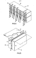
- the closure piece 30 is joined, by epoxy for example, to a wafer 32 that will form the transducing gap 33 and complete the magnetic flux path.
- the wafer 32 includes electrical coils and leads for conducting current representative of signals to be recorded on or read out from a magnetic medium or tape 34 (Fig. 3).
- the wafer 32 is formed with a ferrite substrate 36 on which a spacing layer 38 of A1 2 0 3 is deposited by sputtering for example.
- a series of thin film conductive coils 40A-N which may be made of gold, copper or aluminum, are vapor deposited in a common plane on the spacing layer 38, and are positioned so that each discrete coil 40A- N is associated with a corresponding track element 42A-N, represented in FIG. 3.
- Electrical leads 44 are solder connected to the terminals of each coil to enable passing current to and from the coils for interaction with the magnetic circuit of the head assembly.
- the ferrite may be penetrated and slotted to a shallow depth.
- the shallow cuts allow the use of smaller and narrower cutting saws and wheels that are more accurate than those conventionally used to saw ferrite material used in magnetic head manufacture. In this way, parallelism and precise spacing of the tracks are more easily achieved. Less ferrite material is needed, and the reduction of ferrite breakage improves production yields. Furthermore, only a single glass is needed for this novel construction, as compared to the magnetic head structures that require a two glass bonding, i.e., a high temperature and a low temperature glass.
Landscapes
- Engineering & Computer Science (AREA)
- Manufacturing & Machinery (AREA)
- Magnetic Heads (AREA)
Applications Claiming Priority (2)
| Application Number | Priority Date | Filing Date | Title |
|---|---|---|---|
| US253959 | 1981-04-13 | ||
| US06/253,959 US4396967A (en) | 1981-04-13 | 1981-04-13 | Multielement magnetic head assembly |
Publications (3)
| Publication Number | Publication Date |
|---|---|
| EP0062739A2 true EP0062739A2 (fr) | 1982-10-20 |
| EP0062739A3 EP0062739A3 (en) | 1983-03-09 |
| EP0062739B1 EP0062739B1 (fr) | 1986-07-16 |
Family
ID=22962358
Family Applications (1)
| Application Number | Title | Priority Date | Filing Date |
|---|---|---|---|
| EP82100972A Expired EP0062739B1 (fr) | 1981-04-13 | 1982-02-10 | Assemblage de tête magnétique à éléments multiples et son procédé de fabrication |
Country Status (4)
| Country | Link |
|---|---|
| US (1) | US4396967A (fr) |
| EP (1) | EP0062739B1 (fr) |
| JP (1) | JPS57169917A (fr) |
| DE (1) | DE3271964D1 (fr) |
Cited By (2)
| Publication number | Priority date | Publication date | Assignee | Title |
|---|---|---|---|---|
| EP0689707A4 (fr) * | 1993-03-16 | 1996-05-29 | Shyam C Das | Tete de lecture-ecriture hybride obtenue par les procedes a metal dans l'entrefer et de couche mince |
| CN101377927B (zh) * | 2007-08-30 | 2012-05-02 | 国际商业机器公司 | 制造薄闭合磁头的方法 |
Families Citing this family (9)
| Publication number | Priority date | Publication date | Assignee | Title |
|---|---|---|---|---|
| US4719527A (en) * | 1984-10-31 | 1988-01-12 | Sanyo Electric Co., Ltd. | Composite magnetic head having accurately aligned gaps |
| JPS62234217A (ja) * | 1986-04-03 | 1987-10-14 | Hitachi Ltd | 磁気ヘツド製造方法 |
| US4899434A (en) * | 1987-07-28 | 1990-02-13 | Applied Magnetics Corporation | Method of making a thin film magnetic head with a leveler layer and superstrate |
| US4872079A (en) * | 1987-07-28 | 1989-10-03 | Applied Magnetics Corporation | Thin film magnetic head with a leveler layer |
| US4884157A (en) * | 1987-07-28 | 1989-11-28 | Applied Magnetics Corporation | Thin film magnetic head with coil windings receiving trench |
| US5211734A (en) * | 1989-03-31 | 1993-05-18 | Tdk Corporation | Method for making a magnetic head having surface-reinforced glass |
| US5055957A (en) * | 1989-06-19 | 1991-10-08 | International Business Machines Corporation | Method of making low wear glass for magnetic heads |
| US5063468A (en) * | 1990-05-08 | 1991-11-05 | North American Philips Corporation | Compatible magnetic head assembly |
| US5778514A (en) * | 1993-01-06 | 1998-07-14 | Das Devices, Inc. | Method for forming a transducing head |
Family Cites Families (12)
| Publication number | Priority date | Publication date | Assignee | Title |
|---|---|---|---|---|
| US3145452A (en) * | 1958-03-24 | 1964-08-25 | Iit Res Inst | Method of making a magnetic head |
| US3157748A (en) * | 1961-03-24 | 1964-11-17 | Gen Electric | Magnetic transducer |
| US3579214A (en) * | 1968-06-17 | 1971-05-18 | Ibm | Multichannel magnetic head with common leg |
| US3626396A (en) * | 1968-10-03 | 1971-12-07 | Ibm | Thin-film magnetic recording head |
| US3613228A (en) * | 1969-07-02 | 1971-10-19 | Ibm | Manufacture of multielement magnetic head assemblies |
| GB1409889A (en) * | 1972-12-29 | 1975-10-15 | Data Recording Instr Co | Manufacture of multi-track magnetic heads |
| US3859663A (en) * | 1973-06-18 | 1975-01-07 | Sperry Rand Corp | Multichannel transducer with glass support elements |
| US3909932A (en) * | 1973-10-23 | 1975-10-07 | Ampex | Method of manufacturing a multitrack magnetic head |
| US4072993A (en) * | 1974-11-12 | 1978-02-07 | Matsushita Electric Industrial Co., Ltd. | Multi-element magnetic head |
| JPS5184618A (ja) * | 1975-01-22 | 1976-07-24 | Nippon Electric Co | Jikihetsudo |
| US4298899A (en) * | 1979-12-17 | 1981-11-03 | International Business Machines Corporation | Magnetic head assembly with ferrite core |
| US4366518A (en) * | 1980-09-02 | 1982-12-28 | International Business Machines Corporation | Multi-track head assembly |
-
1981
- 1981-04-13 US US06/253,959 patent/US4396967A/en not_active Expired - Fee Related
- 1981-12-11 JP JP56198696A patent/JPS57169917A/ja active Pending
-
1982
- 1982-02-10 DE DE8282100972T patent/DE3271964D1/de not_active Expired
- 1982-02-10 EP EP82100972A patent/EP0062739B1/fr not_active Expired
Cited By (2)
| Publication number | Priority date | Publication date | Assignee | Title |
|---|---|---|---|---|
| EP0689707A4 (fr) * | 1993-03-16 | 1996-05-29 | Shyam C Das | Tete de lecture-ecriture hybride obtenue par les procedes a metal dans l'entrefer et de couche mince |
| CN101377927B (zh) * | 2007-08-30 | 2012-05-02 | 国际商业机器公司 | 制造薄闭合磁头的方法 |
Also Published As
| Publication number | Publication date |
|---|---|
| US4396967A (en) | 1983-08-02 |
| EP0062739B1 (fr) | 1986-07-16 |
| EP0062739A3 (en) | 1983-03-09 |
| DE3271964D1 (en) | 1986-08-21 |
| JPS57169917A (en) | 1982-10-19 |
Similar Documents
| Publication | Publication Date | Title |
|---|---|---|
| US4901178A (en) | Thin film magnetic head | |
| US3846841A (en) | Multiple magnetic head devices | |
| US4435900A (en) | Method of manufacturing a magnetic head unit | |
| EP0030625A2 (fr) | Assemblage comportant une tête magnétique à noyau en ferrite | |
| EP0062739A2 (fr) | Assemblage de tête magnétique à éléments multiples et son procédé de fabrication | |
| US3601871A (en) | Method for fabricating magnetic read-write head array and product | |
| US3479738A (en) | Magnetic heads | |
| US4774755A (en) | Magnetic head and process for producing same | |
| US4860140A (en) | Magnetic head closure having ferrite substrate and closure and conductive thin film coil deposited in recess of substantially same shape in ferrite substrate | |
| EP0060977A2 (fr) | Procédé de fabrication d'une tête magnétique à elements multiples | |
| US3839784A (en) | Method for fabricating magnetic read-write head array and product | |
| US5267392A (en) | Method of manufacturing a laminated high frequency magnetic transducer | |
| KR930000067B1 (ko) | 자기헤드 | |
| US5276959A (en) | Method of manufacturing a magnetic tape head | |
| US4843486A (en) | Multi-element magnetic head and method of fabricating the same | |
| JPS6233309A (ja) | アジマス付積層ヘツドピ−スの製造方法 | |
| US5883766A (en) | Magnetic head with groove positioned to identify head orientation | |
| KR960005113B1 (ko) | 박막자기헤드 | |
| JPH03198210A (ja) | 薄膜磁気ヘッド | |
| KR960005116B1 (ko) | 멀티채널 박막자기헤드 | |
| JP2664380B2 (ja) | 薄膜磁気ヘッドの製造方法 | |
| JPS63102008A (ja) | 磁気ヘツド及びその製造方法 | |
| JPH0585962B2 (fr) | ||
| JPH06318311A (ja) | 垂直薄膜磁気ヘッド及びその製造方法 | |
| JPS61194618A (ja) | 磁気ヘツド及びその製造方法 |
Legal Events
| Date | Code | Title | Description |
|---|---|---|---|
| PUAI | Public reference made under article 153(3) epc to a published international application that has entered the european phase |
Free format text: ORIGINAL CODE: 0009012 |
|
| AK | Designated contracting states |
Designated state(s): DE FR GB IT NL |
|
| PUAL | Search report despatched |
Free format text: ORIGINAL CODE: 0009013 |
|
| AK | Designated contracting states |
Designated state(s): DE FR GB IT NL |
|
| 17P | Request for examination filed |
Effective date: 19830218 |
|
| GRAA | (expected) grant |
Free format text: ORIGINAL CODE: 0009210 |
|
| AK | Designated contracting states |
Kind code of ref document: B1 Designated state(s): DE FR GB IT NL |
|
| ET | Fr: translation filed | ||
| REF | Corresponds to: |
Ref document number: 3271964 Country of ref document: DE Date of ref document: 19860821 |
|
| ITF | It: translation for a ep patent filed | ||
| PLBE | No opposition filed within time limit |
Free format text: ORIGINAL CODE: 0009261 |
|
| STAA | Information on the status of an ep patent application or granted ep patent |
Free format text: STATUS: NO OPPOSITION FILED WITHIN TIME LIMIT |
|
| 26N | No opposition filed | ||
| PGFP | Annual fee paid to national office [announced via postgrant information from national office to epo] |
Ref country code: FR Payment date: 19900126 Year of fee payment: 9 |
|
| PGFP | Annual fee paid to national office [announced via postgrant information from national office to epo] |
Ref country code: GB Payment date: 19900131 Year of fee payment: 9 |
|
| ITTA | It: last paid annual fee | ||
| PGFP | Annual fee paid to national office [announced via postgrant information from national office to epo] |
Ref country code: NL Payment date: 19900228 Year of fee payment: 9 |
|
| PGFP | Annual fee paid to national office [announced via postgrant information from national office to epo] |
Ref country code: DE Payment date: 19900307 Year of fee payment: 9 |
|
| PG25 | Lapsed in a contracting state [announced via postgrant information from national office to epo] |
Ref country code: GB Effective date: 19910210 |
|
| PG25 | Lapsed in a contracting state [announced via postgrant information from national office to epo] |
Ref country code: NL Effective date: 19910901 |
|
| GBPC | Gb: european patent ceased through non-payment of renewal fee | ||
| NLV4 | Nl: lapsed or anulled due to non-payment of the annual fee | ||
| PG25 | Lapsed in a contracting state [announced via postgrant information from national office to epo] |
Ref country code: FR Effective date: 19911031 |
|
| PG25 | Lapsed in a contracting state [announced via postgrant information from national office to epo] |
Ref country code: DE Effective date: 19911101 |
|
| REG | Reference to a national code |
Ref country code: FR Ref legal event code: ST |