EP0062750A1 - Procédé pour disperser des charges actives à partir d'un engin porteur - Google Patents
Procédé pour disperser des charges actives à partir d'un engin porteur Download PDFInfo
- Publication number
- EP0062750A1 EP0062750A1 EP82101490A EP82101490A EP0062750A1 EP 0062750 A1 EP0062750 A1 EP 0062750A1 EP 82101490 A EP82101490 A EP 82101490A EP 82101490 A EP82101490 A EP 82101490A EP 0062750 A1 EP0062750 A1 EP 0062750A1
- Authority
- EP
- European Patent Office
- Prior art keywords
- submunition
- distribution unit
- distribution
- carrier
- individuals
- Prior art date
- Legal status (The legal status is an assumption and is not a legal conclusion. Google has not performed a legal analysis and makes no representation as to the accuracy of the status listed.)
- Granted
Links
- 238000000034 method Methods 0.000 title claims abstract description 17
- 238000009826 distribution Methods 0.000 claims abstract description 78
- 230000003111 delayed effect Effects 0.000 abstract description 3
- 238000009827 uniform distribution Methods 0.000 description 4
- 208000028659 discharge Diseases 0.000 description 2
- 235000015842 Hesperis Nutrition 0.000 description 1
- 235000012633 Iberis amara Nutrition 0.000 description 1
- 238000013459 approach Methods 0.000 description 1
- 238000010304 firing Methods 0.000 description 1
- 230000002452 interceptive effect Effects 0.000 description 1
- 230000000979 retarding effect Effects 0.000 description 1
- 230000006641 stabilisation Effects 0.000 description 1
- 238000011105 stabilization Methods 0.000 description 1
- 230000000087 stabilizing effect Effects 0.000 description 1
- 230000003068 static effect Effects 0.000 description 1
Images
Classifications
-
- F—MECHANICAL ENGINEERING; LIGHTING; HEATING; WEAPONS; BLASTING
- F42—AMMUNITION; BLASTING
- F42B—EXPLOSIVE CHARGES, e.g. FOR BLASTING, FIREWORKS, AMMUNITION
- F42B12/00—Projectiles, missiles or mines characterised by the warhead, the intended effect, or the material
- F42B12/02—Projectiles, missiles or mines characterised by the warhead, the intended effect, or the material characterised by the warhead or the intended effect
- F42B12/36—Projectiles, missiles or mines characterised by the warhead, the intended effect, or the material characterised by the warhead or the intended effect for dispensing materials; for producing chemical or physical reaction; for signalling ; for transmitting information
- F42B12/56—Projectiles, missiles or mines characterised by the warhead, the intended effect, or the material characterised by the warhead or the intended effect for dispensing materials; for producing chemical or physical reaction; for signalling ; for transmitting information for dispensing discrete solid bodies
- F42B12/58—Cluster or cargo ammunition, i.e. projectiles containing one or more submissiles
- F42B12/62—Cluster or cargo ammunition, i.e. projectiles containing one or more submissiles the submissiles being ejected parallel to the longitudinal axis of the projectile
Definitions
- the invention relates to a method for distributing submunitions according to the preamble of the claim
- the distribution of submunitions using carrier missiles is generally known.
- the submunition can be mines, bomblets, daughter levels, interfering bodies or the like. Rockets in particular are considered as carrier missiles, but also grenades, for example.
- the warheads of the launchers or the grenades above the target area are generally dismantled in various ways and all individual bodies or individuals of submunition are released immediately.
- DE-OS 21 53 994 it is also known to arrange submunitions or general ejection bodies in the warhead of a missile, which is provided with a special distribution unit.
- This distribution unit has a payload carrier plate with a plurality of pivotally attached ejection tubes containing the ejection bodies, which are spread apart before being distributed.
- the distribution unit can be braked before the release of the ejection bodies by additional braking measures, for example by means of a brake parachute or by airbrakes, so that it sinks vertically downwards.
- the distribution unit can still be connected to the remaining rocket or can also be separated from it and transferred to the vertical path on its own.
- the invention has for its object, in particular the to avoid the above disadvantages, ie to carry out a method for distributing submunition in accordance with the preamble of claim 1 in such a way that collisions and other undesirable loads and thus a reduction in the functional reliability of the submunition are at least largely avoided.
- the distribution unit is preferably ejected in the direction of flight of the carrier missile.
- the defined guidance during the ejection movement can e.g. can be achieved in that the distribution units designed as cylindrical or tubular bodies are guided like bullets in corresponding tubular ejection devices of the carrier missile.
- the distribution units can be ejected from individual tubes or in a row one behind the other and / or next to one another, in each case in an ejection tube, if necessary via a sabot. Guided tours in the manner of start rails are also possible.
- the distribution units are provided with aerodynamic stabilization devices, for example guide surfaces, in order to avoid undefined flight movements.
- the at least one distribution unit which initially moves at a distance from one another on the same trajectory, and the rest of the carrier missile are then delayed differently ballistically.
- the distribution unit is provided with a braking device which has a stabilizing effect at the same time, so that the distribution unit is decelerated more and is thereby deflected downward and the carrier missile largely flies over the distribution unit on the ballistic path of the original missile.
- the distance of the distribution unit from the carrier missile generated by the defined primary ejection from the carrier missile and its braking are coordinated with one another in such a way that the distribution unit nevertheless remains at a sufficient distance from the carrier missile when re-approaching due to the braking. Subsequently, the individuals of the submunition can be expelled from the distribution unit and thus released for individual distribution in the secondary output. In this way, possible collisions of the remaining parts of the carrier missile with the distribution unit and also with the submunition are excluded and reproducible ballistic conditions are achieved.
- the submunition individuals are accommodated in a plurality of distribution units which are arranged next to and / or one behind the other as secondary bodies in the carrier missile.
- Their number is small in relation to the total number of individuals per carrier unit.
- approximately the same distribution of the distribution units per carrier missile is achieved in the primary ejection according to the static laws, which has an expansion corresponding to the ejection height. If the number of individuals per distribution unit is now also low, a more or less perfect uniform distribution is achieved with secondary output, based on the individual distribution unit. Since the second ejection point is lower than the first, the less extensive uniform distribution of the individuals per distribution unit advantageously overlaps the equal distribution of the distribution units to a uniform distribution of all individuals of a carrier missile.
- the known distribution methods also cause the individuals to accumulate at the release point when the submunition is released immediately from the carrier missile. This increases the likelihood of collision between individuals and significantly increased with parts of the disassembled carrier missile. This disadvantage is also avoided if the submunition is accommodated in several distribution units, the number of which is correspondingly smaller than the number of individuals.
- the individuals of the submunition are preferably arranged one behind the other in a stack or column-like manner in the distribution unit. Depending on the direction of ejection from the distribution unit, they are furthermore preferably oriented in such a way that they do not have to roll over after being ejected, for example, in order to assume their intended position during the flight. This secondary ejection from the distribution unit can take place in its flight direction.
- the individuals of the submunition are preferably ejected from the distribution unit against the direction of flight or these are withdrawn to the front, so to speak. The distribution unit is additionally accelerated in the direction of flight, while the submunitions are decelerated.
- the speed of the distribution unit is greatly increased, so that a clear distance is again generated between the distribution unit and the submunition. Due to the subsequent different ballistic delay, the trajectories of the two components then diverge in such a way that a collision is not to be feared in the further course of the distribution process.
- the double ejection according to the invention also offers the possibility, according to claim 4, of achieving an optimal deceleration of the distribution unit on the one hand and of the individuals of submunition on the other hand, for example by the distribution unit is slowed down with a brake parachute designed for supersonic speed, while the individuals e.g. with brake parachutes designed for subsonic speeds are so delayed that they do not exceed an intended impact speed on the ground.
- a directed impact on the ground is achieved with correspondingly defined loading directions for which the submunition can be designed.
- the random distribution of the submunition individuals can be e.g. can be extended to a larger area through asymmetrical openings in the brake parachutes.
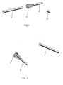
- the 1 shows the primary ejection after the carrier missile 1 with the sleeve-shaped distribution unit 2 containing the submunition has reached the ballistic ejection point above the target area.
- the output of the distribution unit 2 takes place after an ignition pulse from a timer or to the ground appealing distance igniter by means of a pyrotechnic discharge charge.
- the ogive 3 is blown off beforehand or simultaneously with the ejection.
- the distribution unit 2 stabilized by means of the supersonic screen 4 and, like the carrier missile 1, moves on a defined trajectory is shown immediately after the ejection process, ie still close to the carrier missile 1.
- the distance between the two bodies is initially increased until the retarding effect of the parachute 4 predominates and the distribution unit 2 swings into its own flight path according to FIG. 2.
- the remaining carrier missile 1 flies over the distribution unit at a sufficient distance so that collisions are excluded.
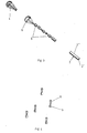
- the submunition here five mines 5
- the submunition is ejected against the direction of flight again with the aid of a pyrotechnic charge from the distribution envelope 2 ′′ closed at its front end 2 ′ after a predetermined delay time from the primary emission.
- the time delay can be based on pyrotechnic, mechanical or electronic
- the brake parachute 4 is also separated.
- the mines 5 arranged in the distribution shell 2 ′′ as a dense stack with their subsonic parachute 6 are separated by the strong successive braking and finally float stabilized and braked according to FIG. 4 in approximately equal distribution to the ground.
- the distribution of the mines 5 on the ground can be influenced.
Landscapes
- Engineering & Computer Science (AREA)
- Chemical & Material Sciences (AREA)
- Combustion & Propulsion (AREA)
- General Engineering & Computer Science (AREA)
- Aiming, Guidance, Guns With A Light Source, Armor, Camouflage, And Targets (AREA)
- Toys (AREA)
Applications Claiming Priority (2)
| Application Number | Priority Date | Filing Date | Title |
|---|---|---|---|
| DE19813111907 DE3111907A1 (de) | 1981-03-26 | 1981-03-26 | Verfahren zum verteilen von submunition |
| DE3111907 | 1981-03-26 |
Publications (2)
| Publication Number | Publication Date |
|---|---|
| EP0062750A1 true EP0062750A1 (fr) | 1982-10-20 |
| EP0062750B1 EP0062750B1 (fr) | 1987-05-13 |
Family
ID=6128332
Family Applications (1)
| Application Number | Title | Priority Date | Filing Date |
|---|---|---|---|
| EP82101490A Expired EP0062750B1 (fr) | 1981-03-26 | 1982-02-26 | Procédé pour disperser des charges actives à partir d'un engin porteur |
Country Status (4)
| Country | Link |
|---|---|
| US (1) | US4498393A (fr) |
| EP (1) | EP0062750B1 (fr) |
| CA (1) | CA1216774A (fr) |
| DE (2) | DE3111907A1 (fr) |
Cited By (1)
| Publication number | Priority date | Publication date | Assignee | Title |
|---|---|---|---|---|
| EP0794405A1 (fr) * | 1996-03-08 | 1997-09-10 | DIEHL GMBH & CO. | Procédé et dispositif pour disperser une charge utile de gros calibre au-dessus d'un objectif |
Families Citing this family (21)
| Publication number | Priority date | Publication date | Assignee | Title |
|---|---|---|---|---|
| FR2547910B1 (fr) * | 1983-06-27 | 1987-01-23 | Lacroix E Tous Artifices | Projectile pour dispersion de munitions |
| DE3414414A1 (de) * | 1984-04-17 | 1985-10-17 | Dynamit Nobel Ag, 5210 Troisdorf | Flugkoerper mit einem fernwirkenden gefechtskopf |
| US4614318A (en) * | 1984-07-17 | 1986-09-30 | The Boeing Company | Passive separation device and method for finned booster |
| DE8437159U1 (de) * | 1984-12-19 | 1986-04-10 | Diehl GmbH & Co, 8500 Nürnberg | Zünder für ein Bomblet |
| US4750403A (en) * | 1986-01-31 | 1988-06-14 | Loral Corporation | Spin dispensing method and apparatus |
| US4676167A (en) * | 1986-01-31 | 1987-06-30 | Goodyear Aerospace Corporation | Spin dispensing method and apparatus |
| US4750423A (en) * | 1986-01-31 | 1988-06-14 | Loral Corporation | Method and system for dispensing sub-units to achieve a selected target impact pattern |
| DE3608107C1 (de) * | 1986-03-12 | 1987-10-01 | Diehl Gmbh & Co | Traegerprojektil fuer Submunition |
| DE3823823A1 (de) * | 1988-07-14 | 1990-01-18 | Diehl Gmbh & Co | Gefechtskopf |
| DE3937762C2 (de) * | 1989-11-14 | 1993-11-25 | Diehl Gmbh & Co | Artilleriegeschoß-Submunition |
| DE4026813C1 (de) * | 1990-08-24 | 1996-09-26 | Rheinmetall Ind Gmbh | Flugkörper zur Bekämpfung eines Hubschraubers |
| US5076511A (en) * | 1990-12-19 | 1991-12-31 | Honeywell Inc. | Discrete impulse spinning-body hard-kill (disk) |
| SE9103081L (sv) * | 1991-10-23 | 1993-02-08 | Bofors Ab | Saett att fraan en skyddskanister separera substridsdelar samt skyddskanister |
| FR2684754B1 (fr) * | 1991-12-10 | 1995-04-07 | Thomson Brandt Armements | Obus dont le culot fait office de pot de parachute d'une sous-munition. |
| DE19517844A1 (de) * | 1995-05-16 | 1996-11-21 | Diehl Gmbh & Co | Dispenser zur Verbringung von Submunition über ein Ziel |
| DE19630796C2 (de) * | 1996-07-31 | 1998-07-09 | Diehl Stiftung & Co | Verbringungseinrichtung für großkalibrige Submunition |
| US6302359B1 (en) * | 2000-04-13 | 2001-10-16 | Capewell Components Company Limited Partnership | Free fall payload distribution device and method |
| SE540780C2 (sv) | 2016-04-06 | 2018-11-06 | Bae Systems Bofors Ab | Delningsbar granat med fallskärmsanordning |
| US10508892B1 (en) * | 2016-08-15 | 2019-12-17 | The United States Of America As Represented By The Secretary Of The Navy | Distributed fuze architecture for highly reliable submunitions |
| SE541612C2 (sv) * | 2016-09-15 | 2019-11-12 | Bae Systems Bofors Ab | Modifierbar delningsbar projektil och metod för att modifiera en projektil |
| SE2300079A1 (en) * | 2023-09-25 | 2025-03-26 | Bae Systems Bofors Ab | Projectile and method for distributing submunitions |
Citations (11)
| Publication number | Priority date | Publication date | Assignee | Title |
|---|---|---|---|---|
| US3221656A (en) * | 1964-03-23 | 1965-12-07 | Adrian P Sutten | Apparatus for high-velocity recovery |
| DE1208220B (de) * | 1960-04-30 | 1965-12-30 | Heinrich Klein Dr Ing | Gefechtskopf fuer einen angetriebenen Flugkoerper |
| FR1533978A (fr) * | 1967-06-13 | 1968-07-26 | Thomson Houston Comp Francaise | Projectile perfectionné à charge utile devant être libérée en un point de la trajectoire |
| FR1579025A (fr) * | 1968-06-17 | 1969-08-22 | ||
| DE2004637A1 (de) * | 1970-02-03 | 1971-08-12 | Dynamit Nobel Ag, 5210 Troisdorf | Gefechtskopf |
| FR2144917A5 (fr) * | 1971-07-02 | 1973-02-16 | Serat | |
| FR2159034A5 (fr) * | 1971-10-29 | 1973-06-15 | Dynamit Nobel Ag | |
| US3797394A (en) * | 1972-09-11 | 1974-03-19 | Thiokol Chemical Corp | Chaff dispenser, method of dispersing chaff |
| US3834312A (en) * | 1973-03-14 | 1974-09-10 | Bofors Ab | Parachute-borne flare assemblage |
| FR2392355A1 (fr) * | 1977-05-27 | 1978-12-22 | Lacroix Tous Artifices E | Charge eclairante lancee a effet continu |
| EP0020226A1 (fr) * | 1979-05-23 | 1980-12-10 | Thomson-Brandt | Dispositif de transport et de largage d'une pluralité de charges contenues dans un conteneur |
Family Cites Families (4)
| Publication number | Priority date | Publication date | Assignee | Title |
|---|---|---|---|---|
| US1365865A (en) * | 1918-06-27 | 1921-01-18 | Jaroslav A Svejda | Illuminating-projectile |
| US3113752A (en) * | 1962-01-23 | 1963-12-10 | Aeronca Mfg Corp | Parachute control apparatus |
| DE2654827A1 (de) * | 1976-12-03 | 1978-06-08 | Rheinmetall Gmbh | Mittels eines traegergeschosses verschiessbare hohlladungstochtergeschosse |
| US4333400A (en) * | 1980-02-01 | 1982-06-08 | The United States Of America As Represented By The Secretary Of The Navy | Two stage parachute fuze recovery system |
-
1981
- 1981-03-26 DE DE19813111907 patent/DE3111907A1/de not_active Withdrawn
-
1982
- 1982-02-26 DE DE8282101490T patent/DE3276340D1/de not_active Expired
- 1982-02-26 EP EP82101490A patent/EP0062750B1/fr not_active Expired
- 1982-03-22 US US06/360,788 patent/US4498393A/en not_active Expired - Fee Related
- 1982-03-25 CA CA000399443A patent/CA1216774A/fr not_active Expired
Patent Citations (11)
| Publication number | Priority date | Publication date | Assignee | Title |
|---|---|---|---|---|
| DE1208220B (de) * | 1960-04-30 | 1965-12-30 | Heinrich Klein Dr Ing | Gefechtskopf fuer einen angetriebenen Flugkoerper |
| US3221656A (en) * | 1964-03-23 | 1965-12-07 | Adrian P Sutten | Apparatus for high-velocity recovery |
| FR1533978A (fr) * | 1967-06-13 | 1968-07-26 | Thomson Houston Comp Francaise | Projectile perfectionné à charge utile devant être libérée en un point de la trajectoire |
| FR1579025A (fr) * | 1968-06-17 | 1969-08-22 | ||
| DE2004637A1 (de) * | 1970-02-03 | 1971-08-12 | Dynamit Nobel Ag, 5210 Troisdorf | Gefechtskopf |
| FR2144917A5 (fr) * | 1971-07-02 | 1973-02-16 | Serat | |
| FR2159034A5 (fr) * | 1971-10-29 | 1973-06-15 | Dynamit Nobel Ag | |
| US3797394A (en) * | 1972-09-11 | 1974-03-19 | Thiokol Chemical Corp | Chaff dispenser, method of dispersing chaff |
| US3834312A (en) * | 1973-03-14 | 1974-09-10 | Bofors Ab | Parachute-borne flare assemblage |
| FR2392355A1 (fr) * | 1977-05-27 | 1978-12-22 | Lacroix Tous Artifices E | Charge eclairante lancee a effet continu |
| EP0020226A1 (fr) * | 1979-05-23 | 1980-12-10 | Thomson-Brandt | Dispositif de transport et de largage d'une pluralité de charges contenues dans un conteneur |
Cited By (2)
| Publication number | Priority date | Publication date | Assignee | Title |
|---|---|---|---|---|
| EP0794405A1 (fr) * | 1996-03-08 | 1997-09-10 | DIEHL GMBH & CO. | Procédé et dispositif pour disperser une charge utile de gros calibre au-dessus d'un objectif |
| US5760330A (en) * | 1996-03-08 | 1998-06-02 | Diehl Gmbh & Co. | Method and apparatus for conveying a large-calibre payload over an operational terrain |
Also Published As
| Publication number | Publication date |
|---|---|
| DE3111907A1 (de) | 1982-10-07 |
| CA1216774A (fr) | 1987-01-20 |
| DE3276340D1 (en) | 1987-06-19 |
| EP0062750B1 (fr) | 1987-05-13 |
| US4498393A (en) | 1985-02-12 |
Similar Documents
| Publication | Publication Date | Title |
|---|---|---|
| EP0062750B1 (fr) | Procédé pour disperser des charges actives à partir d'un engin porteur | |
| DE3840581A1 (de) | Geschoss | |
| EP0806623A1 (fr) | Projectile porteur stabilisé en rotation | |
| EP0049005B1 (fr) | Dispositif pour le lancement d'objets à partir d'un avion | |
| EP1399706B1 (fr) | Projectile d'artillerie a charge utile interchangeable | |
| EP0162250B1 (fr) | Missile avec tête opérant à distance | |
| DE3934042C2 (fr) | ||
| DE69422805T2 (de) | Flugbahnumlenkungsvorrichtung und verfahren für einen gefechtskopf | |
| EP0249677B1 (fr) | Missile volant rapidement | |
| DE3228461C2 (de) | Endphasengelenkter Abwurfkörper | |
| EP0656521B1 (fr) | Charge fumigène à deux composantes | |
| EP0435083A2 (fr) | Antenne d'allumage à distance réglable pour une tête de combat à charge creuse, commutable entre modes d'opération de pénétration ou d'élargissement | |
| EP0249678B2 (fr) | Munition pour combattre des cibles à blindage actif | |
| DE69810879T2 (de) | Projektil mit radialer Wirkrichtung | |
| DE3534101C1 (de) | Geschoß zur Bekämpfung mehrlagiger und gegebenenfalls auch aktiver Panzerungen | |
| DE69422617T2 (de) | Verfahren und vorrichtung zur übertragung von einem gewünschten bewegungsmuster an einem fliegenden gefechtskopf | |
| EP0049778B1 (fr) | Procédé pour distribuer des munitions de combat | |
| DE1578077C2 (de) | Gefechtskopf fuer ein Panzerabwehrgeschoss | |
| DE3216142C1 (en) | Fast-flying projectile with direction-forming charges | |
| DE19845611A1 (de) | Verfahren zur Flugbahnkorrektur von Flugkörpern | |
| DE69207343T2 (de) | Abschiessvorrichtung für Submunitionen | |
| DE3911115A1 (de) | Panzerabwehr-mine | |
| DE3903096C2 (fr) | ||
| DE3727532C2 (de) | Tandemgeschoß | |
| EP2405230A2 (fr) | Dispositif de support pour un projectile fumigène modulaire |
Legal Events
| Date | Code | Title | Description |
|---|---|---|---|
| PUAI | Public reference made under article 153(3) epc to a published international application that has entered the european phase |
Free format text: ORIGINAL CODE: 0009012 |
|
| AK | Designated contracting states |
Designated state(s): BE DE FR IT |
|
| 17P | Request for examination filed |
Effective date: 19830323 |
|
| ITF | It: translation for a ep patent filed | ||
| GRAA | (expected) grant |
Free format text: ORIGINAL CODE: 0009210 |
|
| AK | Designated contracting states |
Kind code of ref document: B1 Designated state(s): BE DE FR IT |
|
| ET | Fr: translation filed | ||
| REF | Corresponds to: |
Ref document number: 3276340 Country of ref document: DE Date of ref document: 19870619 |
|
| BECN | Be: change of holder's name |
Effective date: 19870513 |
|
| RAP2 | Party data changed (patent owner data changed or rights of a patent transferred) |
Owner name: HUELS TROISDORF AKTIENGESELLSCHAFT |
|
| PLBE | No opposition filed within time limit |
Free format text: ORIGINAL CODE: 0009261 |
|
| STAA | Information on the status of an ep patent application or granted ep patent |
Free format text: STATUS: NO OPPOSITION FILED WITHIN TIME LIMIT |
|
| RAP2 | Party data changed (patent owner data changed or rights of a patent transferred) |
Owner name: DYNAMIT NOBEL AKTIENGESELLSCHAFT |
|
| 26N | No opposition filed | ||
| BECN | Be: change of holder's name |
Effective date: 19880316 |
|
| PGFP | Annual fee paid to national office [announced via postgrant information from national office to epo] |
Ref country code: BE Payment date: 19900221 Year of fee payment: 9 |
|
| PG25 | Lapsed in a contracting state [announced via postgrant information from national office to epo] |
Ref country code: BE Effective date: 19910228 |
|
| PGFP | Annual fee paid to national office [announced via postgrant information from national office to epo] |
Ref country code: FR Payment date: 19940216 Year of fee payment: 13 |
|
| ITTA | It: last paid annual fee | ||
| PG25 | Lapsed in a contracting state [announced via postgrant information from national office to epo] |
Ref country code: FR Effective date: 19951031 |
|
| REG | Reference to a national code |
Ref country code: FR Ref legal event code: ST |
|
| PGFP | Annual fee paid to national office [announced via postgrant information from national office to epo] |
Ref country code: DE Payment date: 20000417 Year of fee payment: 19 |
|
| PG25 | Lapsed in a contracting state [announced via postgrant information from national office to epo] |
Ref country code: DE Free format text: LAPSE BECAUSE OF NON-PAYMENT OF DUE FEES Effective date: 20011201 |