EP0062856A1 - Regeleinrichtung für den gasbefeuerten Heizkessel einer Warmwasser-Heizungsanlage - Google Patents
Regeleinrichtung für den gasbefeuerten Heizkessel einer Warmwasser-Heizungsanlage Download PDFInfo
- Publication number
- EP0062856A1 EP0062856A1 EP82102804A EP82102804A EP0062856A1 EP 0062856 A1 EP0062856 A1 EP 0062856A1 EP 82102804 A EP82102804 A EP 82102804A EP 82102804 A EP82102804 A EP 82102804A EP 0062856 A1 EP0062856 A1 EP 0062856A1
- Authority
- EP
- European Patent Office
- Prior art keywords
- gas
- control
- regulator
- air
- control device
- Prior art date
- Legal status (The legal status is an assumption and is not a legal conclusion. Google has not performed a legal analysis and makes no representation as to the accuracy of the status listed.)
- Granted
Links
- XLYOFNOQVPJJNP-UHFFFAOYSA-N water Substances O XLYOFNOQVPJJNP-UHFFFAOYSA-N 0.000 title claims abstract description 15
- 238000010438 heat treatment Methods 0.000 title claims abstract description 11
- 238000009434 installation Methods 0.000 title abstract 2
- 239000007789 gas Substances 0.000 claims abstract description 52
- CURLTUGMZLYLDI-UHFFFAOYSA-N Carbon dioxide Chemical compound O=C=O CURLTUGMZLYLDI-UHFFFAOYSA-N 0.000 claims abstract description 8
- QVGXLLKOCUKJST-UHFFFAOYSA-N atomic oxygen Chemical compound [O] QVGXLLKOCUKJST-UHFFFAOYSA-N 0.000 claims abstract description 6
- 229910052760 oxygen Inorganic materials 0.000 claims abstract description 6
- 239000001301 oxygen Substances 0.000 claims abstract description 6
- 229910002092 carbon dioxide Inorganic materials 0.000 claims abstract description 4
- 239000001569 carbon dioxide Substances 0.000 claims abstract description 4
- 239000003546 flue gas Substances 0.000 claims description 10
- UGFAIRIUMAVXCW-UHFFFAOYSA-N Carbon monoxide Chemical compound [O+]#[C-] UGFAIRIUMAVXCW-UHFFFAOYSA-N 0.000 claims description 9
- 238000002485 combustion reaction Methods 0.000 claims description 9
- 239000008236 heating water Substances 0.000 claims description 6
- 230000000930 thermomechanical effect Effects 0.000 claims description 2
- 230000001105 regulatory effect Effects 0.000 description 4
- 239000012528 membrane Substances 0.000 description 3
- 238000001816 cooling Methods 0.000 description 2
- 241001156002 Anthonomus pomorum Species 0.000 description 1
- 206010053615 Thermal burn Diseases 0.000 description 1
- 238000009833 condensation Methods 0.000 description 1
- 230000005494 condensation Effects 0.000 description 1
- 230000001276 controlling effect Effects 0.000 description 1
- 230000001419 dependent effect Effects 0.000 description 1
- 230000005284 excitation Effects 0.000 description 1
- 239000002737 fuel gas Substances 0.000 description 1
- 238000005259 measurement Methods 0.000 description 1
Images

Classifications
-
- F—MECHANICAL ENGINEERING; LIGHTING; HEATING; WEAPONS; BLASTING
- F23—COMBUSTION APPARATUS; COMBUSTION PROCESSES
- F23N—REGULATING OR CONTROLLING COMBUSTION
- F23N5/00—Systems for controlling combustion
- F23N5/02—Systems for controlling combustion using devices responsive to thermal changes or to thermal expansion of a medium
- F23N5/025—Systems for controlling combustion using devices responsive to thermal changes or to thermal expansion of a medium using electrical or electromechanical means
-
- F—MECHANICAL ENGINEERING; LIGHTING; HEATING; WEAPONS; BLASTING
- F23—COMBUSTION APPARATUS; COMBUSTION PROCESSES
- F23N—REGULATING OR CONTROLLING COMBUSTION
- F23N2225/00—Measuring
- F23N2225/08—Measuring temperature
-
- F—MECHANICAL ENGINEERING; LIGHTING; HEATING; WEAPONS; BLASTING
- F23—COMBUSTION APPARATUS; COMBUSTION PROCESSES
- F23N—REGULATING OR CONTROLLING COMBUSTION
- F23N2233/00—Ventilators
- F23N2233/06—Ventilators at the air intake
-
- F—MECHANICAL ENGINEERING; LIGHTING; HEATING; WEAPONS; BLASTING
- F23—COMBUSTION APPARATUS; COMBUSTION PROCESSES
- F23N—REGULATING OR CONTROLLING COMBUSTION
- F23N2233/00—Ventilators
- F23N2233/06—Ventilators at the air intake
- F23N2233/08—Ventilators at the air intake with variable speed
-
- F—MECHANICAL ENGINEERING; LIGHTING; HEATING; WEAPONS; BLASTING
- F23—COMBUSTION APPARATUS; COMBUSTION PROCESSES
- F23N—REGULATING OR CONTROLLING COMBUSTION
- F23N2235/00—Valves, nozzles or pumps
- F23N2235/12—Fuel valves
- F23N2235/14—Fuel valves electromagnetically operated
-
- F—MECHANICAL ENGINEERING; LIGHTING; HEATING; WEAPONS; BLASTING
- F23—COMBUSTION APPARATUS; COMBUSTION PROCESSES
- F23N—REGULATING OR CONTROLLING COMBUSTION
- F23N2235/00—Valves, nozzles or pumps
- F23N2235/12—Fuel valves
- F23N2235/16—Fuel valves variable flow or proportional valves
-
- F—MECHANICAL ENGINEERING; LIGHTING; HEATING; WEAPONS; BLASTING
- F23—COMBUSTION APPARATUS; COMBUSTION PROCESSES
- F23N—REGULATING OR CONTROLLING COMBUSTION
- F23N2235/00—Valves, nozzles or pumps
- F23N2235/12—Fuel valves
- F23N2235/18—Groups of two or more valves
-
- F—MECHANICAL ENGINEERING; LIGHTING; HEATING; WEAPONS; BLASTING
- F23—COMBUSTION APPARATUS; COMBUSTION PROCESSES
- F23N—REGULATING OR CONTROLLING COMBUSTION
- F23N2235/00—Valves, nozzles or pumps
- F23N2235/12—Fuel valves
- F23N2235/20—Membrane valves
-
- F—MECHANICAL ENGINEERING; LIGHTING; HEATING; WEAPONS; BLASTING
- F23—COMBUSTION APPARATUS; COMBUSTION PROCESSES
- F23N—REGULATING OR CONTROLLING COMBUSTION
- F23N2235/00—Valves, nozzles or pumps
- F23N2235/12—Fuel valves
- F23N2235/24—Valve details
-
- F—MECHANICAL ENGINEERING; LIGHTING; HEATING; WEAPONS; BLASTING
- F23—COMBUSTION APPARATUS; COMBUSTION PROCESSES
- F23N—REGULATING OR CONTROLLING COMBUSTION
- F23N5/00—Systems for controlling combustion
- F23N5/003—Systems for controlling combustion using detectors sensitive to combustion gas properties
- F23N5/006—Systems for controlling combustion using detectors sensitive to combustion gas properties the detector being sensitive to oxygen
-
- F—MECHANICAL ENGINEERING; LIGHTING; HEATING; WEAPONS; BLASTING
- F23—COMBUSTION APPARATUS; COMBUSTION PROCESSES
- F23N—REGULATING OR CONTROLLING COMBUSTION
- F23N5/00—Systems for controlling combustion
- F23N5/18—Systems for controlling combustion using detectors sensitive to rate of flow of air or fuel
Definitions
- Hot water collective heating systems are often operated with a flow temperature that is controlled depending on the outside temperature, while the heat supply to the individual rooms is regulated by radiator valves provided there, which can be adjusted manually or by means of a thermostat, depending on the heat demand in the room concerned.
- a temperature controller for collective heating systems which controls a control valve located in the supply or return line and is connected on the input side to two temperature sensors, one of which is the temperature in the supply line and the other the temperature in the return line measures. The controller is designed so that a predetermined temperature difference is maintained between the flow and return.
- DE-OS 27 47 969 shows a control device of this type for a heating system with admixture control, in which the control device acts on a mixing valve in order to maintain a predetermined temperature difference between flow and return.
- a thermostatic radiator valve provided there opens a larger flow cross-section and thus increases the amount of water flowing through. As a result, the heating water flows through the radiator faster, cooling less and thus the return temperature rises. In order to maintain a predetermined temperature difference, more hot water is consequently supplied by the mixing valve and the flow temperature is increased.
- the demand-based control is carried out on the water side with the aid of a flow or mixing valve, while the burner and thus the temperature of the hot water is controlled depending on the outside temperature, but not on the actual heat demand in the rooms.
- the object of the invention is to control the burner itself as a function of the heat requirement and in this way to feed it only that amount of gas which is required to generate the required heat.
- This object is achieved by the invention characterized in claim 1.
- the temperature difference between the flow and return of the heating water to the consumer that is to say, for example, to the radiators of a collective heating system, serves as a parameter for the actual heat demand.
- the amount of gas supplied to the burner of the boiler is regulated.
- the combustion air volume supplied to the boiler is regulated at the same time.
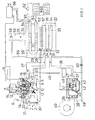
- the gas control device controlling the gas supply has the structure known from the company publication D3H-29 HONEYWELL COMPACT VALVES V4600 / 8600, the servo pressure regulator provided there, which can be adjusted by hand, by means of a servo pressure regulator which can be adjusted in terms of its setpoint by means of an electromagnetic drive, in accordance with the older DE- OS 30 15 980 is replaced.
- a safety valve 4 and a main gas valve 5 are connected in series between inlet 2 and outlet 3.
- the safety valve 4 with switch-on pushbutton 6 and restart lock 7 is irrelevant to the mode of operation of the invention and is therefore not discussed in detail.
- the closing body 5 of the main gas valve is biased in the closing direction by a closing spring 8 and can be lifted off the valve seat 11 against the force of this closing spring 8 by means of a membrane 9 by the servo control pressure in the chamber 10.
- the control pressure for the chamber 10 is supplied via the channel 12 by a servo pressure regulator 13, the setpoint 5 of which can be adjusted by means of an electromagnetic drive 14.
- Room In one to be heated by the hot water heating system Room is the room thermostat 15, the contact of which closes as soon as the room temperature measured by its temperature sensor falls below the setpoint set on the room thermostat 15.
- the solenoid 16 of the gas control device 1 With the closing of this contact, the solenoid 16 of the gas control device 1 is connected to 'voltage, so that on the one hand it allows the input gas pressure to pass into the chamber 19 via the line 17 and a throttle point 18 and on the other hand with its closing body 20 the connection of this chamber to the channel 21 and blocked with this with the outlet 3. Consequently, a control pressure builds up in the chamber 19 which is dependent on the position of the throttle body 22 of the pressure regulator and which reaches the control chamber 10 of the diaphragm drive for the main gas valve 5, 11 via the channel 12 and lifts the closing body 5 from the seat 11. Thus, gas flows via line 23 to injector nozzle 24, which faces gas inlet 25 of burner 26.
- the gas stream sucks in primary air and also feeds it to the burner 26.
- the pilot burner 28 is connected to the gas control valve 1 via an ignition line 27. Its flame heats the thermocouple 29, which holds the safety valve 4 open via the magnet insert 30.
- a second injector nozzle 31 is provided, which faces a secondary air inlet 32 of the boiler 33.
- the secondary air inlet 32 opens into an air distributor pipe 35 provided with air outlet holes 34.
- the second injector nozzle 31 is connected via a line 36 to the outlet 37 of an air control valve .38, the inlet 39 of which is connected to a compressed air source in the form of a fan 40.
- the closing body 41 of the air control valve 38 is biased in the closing direction by a spring 42 and can be lifted off the seat 44 by a membrane 43 as soon as the pressure in the drive chamber 45 exceeds the forces exerted by the closing spring 42 and the pressure in the outlet 37 on the membrane 43.
- the control pressure in the chamber 45 also comes from the chamber 19 below the throttle body 22 of the servo pressure regulator 13 via a line 46. In this way, the gas supply and secondary air supply are regulated in the same direction by the servo pressure regulator 13.
- the sensor 47 of a flow switch 48 is located in the outlet 37 of the air control valve 38. Its normally open contact, which is closed by the air flow, is switched into the excitation circuit of the solenoid 16.
- the burner 26 heats a heat exchanger 51, which is connected to the radiators 53 via a circulation pump 52.
- the exhaust gases leave the boiler 33 through the flue gas exhaust 54, which passes into the chimney 56 via a draft interrupter 55.
- gas inlet 25 secondary air inlet 32 and flue gas outlet 54
- the housing 57 of the boiler 33 is closed on all sides.
- An air outlet nozzle 58 projects into the chimney 56 and is connected via a line 59 to the outlet 37 of the air control valve. With the help of this air outlet nozzle 58, an artificial draft is generated in the chimney 56.
- a throttle 60 the auxiliary air flow from the nozzle 58 can be adapted to the secondary air flow.
- a temperature sensor 63 is provided in the heating water supply line 62 from the heat exchanger 51 to the radiators 53 and a second temperature sensor 65 is provided in the return line 64.
- the outputs of both temperature sensors are connected to a controller 66, which is connected on the output side to the magnetic drive 14 of the servo pressure controller 13.
- the amount of gas supplied to the burner 26 is modulated as a function of the heat requirement. If the room temperature reaches the setpoint specified on the room thermostat 15, this interrupts the circuit of the switch-on solenoid valve, as a result of which the servo pressure regulator 13 no longer delivers control pressure into the diaphragm chamber 10 of the diaphragm drive for the main gas valve 5, 11, so that it closes under the influence of its closing spring 8. With the modulation and change in the gas supply to the main burner 26, the associated quantity of secondary air is continuously adapted to the gas throughput simultaneously via the control pressure line 46 and the air control valve 38. In this way, complete combustion and optimal utilization are achieved of the fuel gas.
- thermomechanical controller can also be used, as described for example in DE-PS 19 61 806 or DE-OS 27 47 969.
- the two temperature sensors 63 and 65 are shown as expansion sensors, which act hydraulically on an actuator via capillary tubes. This then directly mechanically adjusts the setpoint of the servo pressure regulator 13.
- the embodiment according to FIG. 2 differs from that according to FIG. 1 essentially by a changed control of the secondary air quantity depending on the gas throughput. While gas supply and secondary air supply are influenced in the same direction in the embodiment according to FIG. 1 with the help of the same servo pressure regulator 13, this acts in FIG. 2 only on the gas control valve and thus on the gas supply to the burner 26. At the same time, however, the amount of primary air drawn in via the injector nozzle 24 is changed in the same direction. To control the secondary air volume supplied and sucked in via the second injector nozzle 31, on the other hand, an oxygen or carbon dioxide sensor 70 is provided in the flue gas outlet 54, the output signal of which is fed to a controller 71.
- the controller 71 supplies an output signal to the magnetic drive 72 of the servo pressure controller 73 placed on the air control valve 38, whereby the setpoint of this pressure controller increases and at the same time the air control valve 41, 44 is opened further. Secondary air thus flows to the air distributor pipe 35, so that the excess air measured by the sensor 70 increases. If the excess air is too high, conversely, the amount of secondary air supplied via the air control valve 38 is throttled.
- the blower itself can also be controllable.
- the output line 74 of the controller 71 is connected via a connection 74 'directly to a blower control circuit, via which the speed and thus the performance of the blower can be influenced.
- the controllers 66 and 71 can be combined to form a common controller, possibly a digital controller using a microprocessor.
- a measurement of the CO 2 content of the flue gases can also be used to control the amount of secondary air.
- the circuit arrangement according to FIG. 2 works in the same way as previously described with reference to FIG. 1.
- the heating water consumer 53 itself serves as a measuring section for determining the amount of heat required.
- the greater the heat requirement the more the temperature difference between flow 62 and return 64 increases. Accordingly, the setpoint of the servo pressure controller 13 is adjusted via the guide controller 66 and the magnetic drive 14 and thus the gas throughput to the burner is controlled.
Landscapes
- Engineering & Computer Science (AREA)
- Chemical & Material Sciences (AREA)
- Combustion & Propulsion (AREA)
- Mechanical Engineering (AREA)
- General Engineering & Computer Science (AREA)
- Control Of Combustion (AREA)
Abstract
Description
- Warmwasser-Sammelheizungsanlagen werden vielfach mit einer von der Außentemperatur abhängig gesteuerten Vorlauftemperatur betrieben, während die Wärmezufuhr zu den einzelnen Räumen durch dort vorgesehene, von Hand oder mittels eines Thermostaten verstellbare Radiatorventile in Abhängigkeit vom Wärmebedarf im betreffenden Raum geregelt wird. Des weiteren ist aus DE-PS 19 61 806 ein Temperaturregler für Sammelheizungsanlagen bekannt, der ein in der Vor- oder Rücklaufleitung liegendes Stellventil steuert und eingangsseitig an zwei Temperaturfühler angeschlossen ist, von denen der eine die Temperatur in der Vorlaufleitung und der andere die Temperatur in der Rücklaufleitung mißt. Der Regler ist so ausgebildet, daß zwischen Vor- und Rücklauf eine vorgegebene Temperaturdifferenz eingehalten wird. Weiterhin zeigt die DE-OS 27 47 969 eine Regelvorrichtung dieser Art für eine Heizungsanlage mit Beimischregelung, in welcher die Regelvorrichtung zwecks Aufrechterhaltung einer vorgegebenen Temperaturdifferenz zwischen Vorlauf und Rücklauf auf ein Mischventil einwirkt. Wird im zu beheizenden Raum mehr Wärme benötigt, so öffnet ein dort vorgesehenes thermostatisches Heizkörperventil einen größeren Durchflußquerschnitt und erhöht damit die durchfließende Wassermenge. Dies hat zur Folge, daß das Heizwasser schneller durch den Heizkörper fließt, dabei sich weniger abkühlt und somit die Rücklauftemperatur ansteigt. Um eine vorgegebene Temperaturdifferenz einzuhalten, wird folglich vom Mischventil mehr Heißwasser zugeführt und damit die Vorlauftemperatur erhöht.
- Bei diesen und anderen bekannten Warmwasserheizungsanlagen erfolgt somit die bedarfsabhängige Regelung wasserseitig mit Hilfe eines Vorlauf- oder Beimischventils, während der Brenner und damit die Temperatur des Heißwassers allenfalls in Abhängigkeit von der Außentemperatur,nicht aber vom eigentlichen Wärmebedarf in den Räumen gesteuert wird.
- Aufgabe der Erfindung ist es, den Brenner selbst in Abhängigkeit vom Wärmebedarf zu steuern und ihm auf diese Weise nur diejenige Gasmenge zuzuführen, welche zur Erzeugung der benötigten Wärme erforderlich ist. Diese Aufgabe wird gelöst durch die im Anspruch 1 gekennzeichnete Erfindung. Als Kenngröße für den tatsächlichen Wärmebedarf dient hier wie beim eingangs erwähnten Stand der Technik die Temperaturdifferenz zwischen Vorlauf und Rücklauf des Heizwassers zum Verbraucher, also beispielsweise zu den Heizkörpern einer Sammelheizungsanlage. In Abhängigkeit hiervon wird die dem Brenner des Heizkessels zugeführte Gasmenge geregelt. Um eine optimale Verbrennung und damit eine bestmögliche Ausnutzung dieser Gasmenge zu gewährleisten, erfolgt gleichzeitig eine Regelung der dem Heizkessel zugeführten Verbrennungsluftmenge. Vorteilhafte Ausgestaltungen der Erfindung ergeben sich aus den Unteransprüchen.
- Die Erfindung wird nachfolgend anhand zweier in den Zeichnungen wiedergegebener Ausführungsbeispiele erläutert. Dabei zeigt:
- Fig. 1 eine Warmwasserheizungsanlage, bei der in Abhängigkeit von der Differenz zwischen Vor- und Rücklauftemperatur durch einen gemeinsamen auf ein Gasregelgerät aufgesetzten Servodruckregler sowohl die dem Brenner zugeführte Gasmenge als auch die zugeführte Verbrennungsluftmenge gleichzeitig dem Wärmebedarf angepaßt werden; während
- Fig. 2 eine Ausführungsform wiedergibt, bei der die Temperaturdifferenz die Gaszufuhr steuert, während die zu dessen vollständiger Verbrennung erforderliche Verbrennungsluftmenge in Abhängigkeit von der Sauerstoff-oder Kohlendioxydkonzentration des Rauchgases ermittelt und über ein Luftmengenstellglied der Gasmenge fortlaufend angepaßt wird.
- In beiden Ausführungsbeispielen hat das die Gaszufuhr steuernde Gasregelgerät den aus der Firmendruckschrift D3H-29 HONEYWELL KOMPAKT-VENTILE V4600/8600 bekannten Aufbau, wobei der dort vorgesehene, von Hand einstellbare Servodruckregler durch einen mittels einen Elektromagnetantrieb hinsichtlich seines Sollwerts einstellbaren Servodruckregler gemäß der älteren DE-OS 30 15 980 ersetzt ist. Im Gasregelgerät 1 sind zwischen Einlaß 2 und Auslaß 3 ein Sicherheitsventil 4 und ein Hauptgasventil 5 in Reihe geschaltet. Das Sicherheitsventil 4 mit Einschaltdrucktaste 6 und Wiedereinschaltsperre 7 ist für die Wirkungsweise der Erfindung ohne Belang und wird folglich nicht im einzelnen erörtert. Der Schließkörper 5 des Hauptgasventils ist durch eine Schließfeder 8 in Schließrichtung vorgespannt und kann über eine Membran 9 durch den Servosteuerdruck in der Kammer 10 gegen die Kraft dieser Schließfeder 8 vom Ventilsitz 11 abgehoben werden. Den Steuerdruck für die Kammer 10 liefert über den Kanal 12 ein Servodruckregler 13, dessen Sollwert 5 mit Hilfe eines Elektromagnetantriebs 14 verstellbar ist. In einem durch die Warmwasserheizungsanlage zu beheizenden Raum befindet sich der Raumthermostat 15, dessen Kontakt schließt, sobald die von seinem Temperaturfühler gemessene Raumtemperatur den am Raumthermostaten 15 eingestellten Sollwert unterschreitet. Mit dem Schließen dieses Kontakts wird das Einschaltmagnetventil 16 des Gasregelgeräts 1 an' Spannung gelegt, so daß es einerseits den Eingangsgasdruck über die Leitung 17 und eine Drosselstelle 18 in die Kammer 19 gelangen läßt und andererseits mit seinem Schließkörper 20 die Verbindung dieser Kammer mit dem Kanal 21 und über diesen mit dem Auslaß 3 sperrt. Folglich baut sich in der Kammer 19 ein von der Stellung des Drosselkörpers 22 des Druckreglers abhängiger Steuerdruck auf, der über den Kanal 12 in die Steuerkammer 10 des Membranantriebs für das Hauptgasventil 5, 11 gelangt und den Schließkörper 5 vom Sitz 11 abhebt. Damit strömt Gas über die Leitung 23 zur Injektordüse 24, welche dem Gaseinlaß 25 des Brenners 26 gegenübersteht. Der Gasstrom saugt zugleich Primärluft an und führt sie ebenfalls dem Brenner 26 zu. Über eine Zündleitung 27 ist der Zündbrenner 28 an das Gasregelventil 1 angeschlossen. Seine Flamme erwärmt das Thermoelement 29, welches über den Magneteinsatz 30 das Sicherheitsventil 4 offenhält.
- Da die vom Gasstrom durch die Injektordüse 24 angesaugte Primärluft für eine vollständige Verbrennung des Gases nicht ausreicht, ist eine zweite Injektordüse 31 vorgesehen, welche einem Sekundärlufteinlaß 32 des Boilers 33 gegenübersteht. Der Sekundärlufteinlaß 32 mündet in ein mit Luftaustrittslöchern 34 versehenes Luftverteilerrohr 35. Die zweite Injektordüse 31 steht über eine Leitung 36 mit dem Ausgang 37 eines Luftregelventils .38 in Verbindung, dessen Eingang 39 an eine Druckluftquelle in Form eines Gebläses 40 angeschlossen ist. Der Schließkörper 41 des Luftregelventils 38 ist durch eine Feder 42 in Schließrichtung vorgespannt und kann von einer Membran 43 vom Sitz 44 abgehoben werden, sobald der Druck in der Antriebskammer 45 die von der Schließfeder 42 und vom Druck im Ausgang 37 ausgeübten Kräfte auf die Membran 43 übersteigt. Der Steuerdruck in der Kammer 45 kommt über eine Leitung 46 ebenfalls aus der Kammer 19 unterhalb des Drosselkörpers 22 des Servodruckreglers 13. Auf diese Weise werden Gaszufuhr und Sekundärluftzufuhr gleichsinnig durch den Servodruckregler 13 geregelt. Im Auslaß 37 des Luftregelventils 38 liegt der Fühler 47 eines Strömungsschalters 48. Sein durch den Luftstrom schließender Arbeitskontakt ist in den Erregerstromkreis des Einschaltmagnetventils 16 eingeschaltet.
- Der Brenner 26 beheizt einen Wärmetauscher 51, der über eine Umwälzpumpe 52 an die Heizkörper 53 angeschlossen ist. Die Abgase verlassen den Boiler 33 durch den Rauchgasabzug 54, der über einen Zugunterbrecher 55 in den Schornstein 56 übergeht. Mit Ausnahme von Gaseinlaß 25, Sekundärlufteinlaß 32 und Rauchgasabzug 54 ist das Gehäuse 57 des Boilers 33 allseitig geschlossen. In den Schornstein 56 ragt eine Luftaustrittsdüse 58 hinein, welche über eine Leitung 59 an den Auslaß 37 des Luftregelventils angeschlossen ist. Mit Hilfe dieser Luftaustrittsdüse 58 wird ein künstlicher Zug im Schornstein 56 erzeugt. Mittels einer Drossel 60 kann der Hilfsluftstrom aus der Düse 58 dem Sekundärluftstrom angepaßt werden. Bei hohen Schornsteinen empfiehlt es sich vielfach, die Leitung 59 nicht an den Auslaß 37, sondern über die Leitung 59' an den Einlaß 39 des Luftregelventils 38, d. h. unmittelbar an das Gebläse 40 anzuschließen. Um eine Kondensation der Abgase im Schornstein 56 infolge Rauchgasabkühlung zu vermeiden,
kann es ratsam sein, die den künstlichen Zug erzeugende Luft vorzuwärmen. Dies ist in Fig. 1 dadurch gestrichelt angedeutet, daß die Zuleitung zur Düse 58 im Bereich 59" teilweise im Inneren des Boilers 33 entlanggeführt ist. - In der Heizwasservorlaufleitung 62 vom Wärmetauscher 51 zu den Heizkörpern 53 ist ein Temperaturfühler 63 und in der Rücklaufleitung 64 ein zweiter Temperaturfühler 65 vorgesehen. Die Ausgänge beider Temperaturfühler sind an einen Regler 66 angeschlossen, der ausgangsseitig mit dem Magnetantrieb 14 des Servodruckreglers 13 in Verbindung steht.
- Sobald die Temperatur in dem zu beheizenden Raum unter den Sollwert des Raumthermostaten 15 absinkt, schließt dieser seinen Kontakt, schaltet das Einschaltmagnetventil 16 ein und mit ihm den Servodruckregler 13. Dieser öffnet das Hauptgasventil 5,11, so daß der Hauptbrenner 26 zündet und das den Wärmetauscher 51 durchfließende Heizwasser erwärmt. Ist der zu beheizende Raum relativ kalt, so kühlt sich das Wasser stark ab und die Temperaturfühler 63 und 65 melden eine starke Temperaturdifferenz an den Regler 66. Ist diese Temperaturdifferenz größer als ein vorgegebener Sollwert, so verstellt der Magnetantrieb 14 den Servodruckregler 13 in Richtung auf einen höheren Steuerdruck, so daß das Hauptgasventil 5, 11 noch weiter geöffnet wird. Sinkt hingegen die Temperaturdifferenz, so wird die Gaszufuhr auf dem gleichen Wege gedrosselt. Auf diese Weise wird die dem Brenner 26 zugeführte Gasmenge in Abhängigkeit vom Wärmebedarf moduliert. Erreicht die Raumtemperatur den am Raumthermostaten 15 vorgegebenen Sollwert, so unterbricht dieser den Stromkreis des Einschaltmagnetventils, dadurch liefert der Servodruckregler 13 keinen Steuerdruck mehr in die Membrankammer 10 des Membranantriebs für das Hauptgasventil 5, 11, so daß dieses unter dem Einfluß seiner Schließfeder 8 schließt. Mit der Modulation und Veränderung der Gaszufuhr zum Hauptbrenner 26 wird gleichzeitig über die Steuerdruckleitung 46 und das Luftregelventil 38 die zugehörige Sekundärluftmenge dem Gasdurchsatz fortlaufend angepaßt. Man erreicht auf diese Weise eine vollständige Verbrennung und optimale Ausnutzung des Brenngases. Schließt das Gasregelventil 5, 11, so verschwindet gleichzeitig der Steuerdruck auf der Leitung 46, so daß auch das Luftregelventil 38 schließt und dem Sekundärlufteinlaß 32 keine Sekundärluft mehr zugeführt wird. Da das Gehäuse 57 des Boilers 33 bis auf die beiden Einlaßöffnungen 25 und 32 eingangsseitig geschlossen ist, herrscht innerhalb des Boilers nahezu kein Zug mehr, so daß die darin enthaltene Wärme nicht über den Rauchgasabzug 54 entweicht. Auch dies trägt zur Verbesserung des Wirkungsgrades der Heizungsanlage bei.
- Anstelle des im Ausführungsbeispiel dargestellten elektrischen oder elektronischen Reglers 66 kann auch ein thermomechanischer Regler Verwendung finden, wie er beispielsweise in der DE-PS 19 61 806 bzw. DE-OS 27 47 969 beschrieben ist. Dort sind die beiden Temperaturfühler 63 und 65 als Ausdehnungsfühler dargestellt, die über Kapillarrohre hydraulisch auf ein Stellglied einwirken. Dieses verstellt dann mechanisch unmittelbar den Sollwert des Servodruckreglers 13.
- Die Ausführungsform nach Fig. 2 unterscheidet sich von derjenigen gemäß Fig. 1 im wesentlichen durch eine geänderte Steuerung der Sekundärluftmenge in Abhängigkeit vom Gasdurchsatz. Während beim Ausführungsbeispiel nach Fig. 1 Gaszufuhr und Sekundärluftzufuhr gleichsinnig mit Hilfe des gleichen Servodruckreglers 13 beeinflußt werden, wirkt dieser in Fig. 2 nur auf das Gasregelventil und damit auf die Gaszufuhr zum Brenner 26 ein. Zugleich wird allerdings auch die über die Injektordüse 24 angesaugte Primärluftmenge gleichsinnig verändert. Zur Steuerung der über die zweite Injektordüse 31 zugeführten und angesaugten Sekundärluftmange hingegen ist im Rauchgasabzug 54 ein Sauerstoff-oder Kohlendioxydfühler 70 vorgesehen, dessen Ausgangssignal einem Regler 71 zugeführt ist. Unterschreitet der Sauerstoffüberschuß (Luftüberschuß) im Rauchgasabzug 54 einen vorgegebenen Sollwert, so liefert der Regler 71 ein Ausgangssignal an den Magnetantrieb 72 des auf das Luftregelventil 38 aufgesetzten Servodruckreglers 73, wodurch der Sollwert dieses Druckreglers erhöht und damit zugleich das Luftregelventil 41, 44 weiter geöffnet wird. Damit fließt mehr.Sekundärluft zum Luftverteilerrrohr 35, so daß der vom Fühler 70 gemessene Luftüberschuß zunimmt. Ein zu hoher Luftüberschuß führt umgekehrt zu einer Drosselung der über das Luftregelventil 38 zugeführten Sekundärluftmenge. Anstelle der Zwischenschaltung eines Luftregelventils 38 zwischen Gebläse 40 und Sekundärluftdüse 31 kann auch das Gebläse selbst regelbar sein. In diesem Falle wird die Ausgangsleitung 74 des Reglers 71 über eine Verbindung 74' unmittelbar an eine Gebläsesteuerschaltung angeschlossen, über die die Drehzahl und damit die Leistung des Gebläses beeinflußbar ist. Die Regler 66 und 71 können zu einem gemeinsamen Regler, ggf. zu einem Digitalregler unter Verwendung eines Mikroprozessors zusammengefaßt werden. Anstelle des Sauerstoffüberschusses kann auch eine Messung des C02-Gehalts der Rauchgase zur Steuerung der Sekundärluftmenge herangezogen werden. Hinsichtlich der Steuerung der Gaszufuhr in Abhängigkeit von der Temperaturdifferenz am Eingang und Ausgang des Wärmetauschers arbeitet die Schaltungsanordnung nach Fig. 2 in der gleichen Weise wie zuvor anhand von Fig. 1 beschrieben. Während der Raumthermostat 15 durch Betätigen seines Kontakts anzeigt, ob dem Raum Wärme zugeführt werden soll, dient der Heizwasserverbraucher 53 selbst als Meßstrecke zur Ermittlung des Betrages der erforderlichen Wärmezufuhr. Je größer der Wärmebedarf ist, umso mehr wächst die Temperaturdifferenz zwischen Vorlauf 62 und Rücklauf 64 an. Dementsprechend wird über den Führungsregler 66 und den Magnetantrieb 14 der Sollwert des Servodruckreglers 13 verstellt und damit der Gasdurchsatz zum Brenner gesteuert.
Claims (10)
Applications Claiming Priority (2)
| Application Number | Priority Date | Filing Date | Title |
|---|---|---|---|
| DE3114942 | 1981-04-13 | ||
| DE19813114942 DE3114942A1 (de) | 1981-04-13 | 1981-04-13 | Regeleinrichtung fuer den gasbefeuerten heizkessel einer warmwasser-heizungsanlage |
Publications (2)
| Publication Number | Publication Date |
|---|---|
| EP0062856A1 true EP0062856A1 (de) | 1982-10-20 |
| EP0062856B1 EP0062856B1 (de) | 1986-07-16 |
Family
ID=6130069
Family Applications (1)
| Application Number | Title | Priority Date | Filing Date |
|---|---|---|---|
| EP82102804A Expired EP0062856B1 (de) | 1981-04-13 | 1982-04-02 | Regeleinrichtung für den gasbefeuerten Heizkessel einer Warmwasser-Heizungsanlage |
Country Status (2)
| Country | Link |
|---|---|
| EP (1) | EP0062856B1 (de) |
| DE (2) | DE3114942A1 (de) |
Cited By (6)
| Publication number | Priority date | Publication date | Assignee | Title |
|---|---|---|---|---|
| EP0229319A3 (en) * | 1985-12-16 | 1988-02-10 | Honeywell B.V. | Hot water heating installation with a heat consumption meter |
| US4785846A (en) * | 1986-12-24 | 1988-11-22 | Honeywell B.V. | Gas control apparatus with a pressure regulator |
| WO1993000559A1 (en) * | 1991-06-29 | 1993-01-07 | Jin Min Choi | Hot water boiler system |
| US6003544A (en) * | 1996-04-02 | 1999-12-21 | Sit La Precisa S.R.L. | Valve unit for controlling the delivery pressure of a gas |
| US10100938B2 (en) | 2008-12-08 | 2018-10-16 | Robertshaw Controls Company | Variable flow gas valve and method for controlling same |
| CN113587140A (zh) * | 2021-08-09 | 2021-11-02 | 吉林同鑫热力集团股份有限公司 | 一种锅炉燃烧优化系统 |
Families Citing this family (1)
| Publication number | Priority date | Publication date | Assignee | Title |
|---|---|---|---|---|
| DE3742807A1 (de) * | 1987-12-17 | 1989-07-13 | Peter Huber | Temperiereinrichtung |
Citations (10)
| Publication number | Priority date | Publication date | Assignee | Title |
|---|---|---|---|---|
| US1604271A (en) * | 1924-12-17 | 1926-10-26 | Ferdinand J Friedman | Furnace equipment |
| GB918844A (en) * | 1958-11-13 | 1963-02-20 | Radiation Ltd | Improvements in or relating to temperature-controlled, gas-fired water heaters |
| US3960320A (en) * | 1975-04-30 | 1976-06-01 | Forney Engineering Company | Combustion optimizer |
| FR2324050A1 (fr) * | 1975-09-11 | 1977-04-08 | Bosch Gmbh Robert | Dispositif de reglage pour une installation de chauffage central a l'eau chaude |
| US4034911A (en) * | 1975-12-04 | 1977-07-12 | Emerson Electric Co. | Burner control system |
| FR2337316A1 (fr) * | 1975-12-29 | 1977-07-29 | Cidelcem | Generateur d'eau chaude a chauffage instantane |
| FR2356882A1 (fr) * | 1976-06-28 | 1978-01-27 | Claeys Flandria Nv | Perfectionnements aux procedes et dispositifs pour maintenir pratiquement constant a divers regimes de fonctionnement le rendement d'appareils a evacuation forcee comportant un dispositif de combustion |
| WO1980001603A1 (en) * | 1979-01-31 | 1980-08-07 | Jydsk Varmekedelfab As | Method and apparatus for regulating the combustion in a furnace |
| EP0036613A1 (de) * | 1980-03-20 | 1981-09-30 | Honeywell B.V. | Durch einen Temperaturfühler steuerbare Regeleinrichtung für einen gasbefeuerten Wasser- oder Lufterhitzer |
| GB2075718A (en) * | 1980-04-28 | 1981-11-18 | Hitachi Ltd | Method and apparatus for combustion control |
-
1981
- 1981-04-13 DE DE19813114942 patent/DE3114942A1/de not_active Withdrawn
-
1982
- 1982-04-02 EP EP82102804A patent/EP0062856B1/de not_active Expired
- 1982-04-02 DE DE8282102804T patent/DE3271988D1/de not_active Expired
Patent Citations (10)
| Publication number | Priority date | Publication date | Assignee | Title |
|---|---|---|---|---|
| US1604271A (en) * | 1924-12-17 | 1926-10-26 | Ferdinand J Friedman | Furnace equipment |
| GB918844A (en) * | 1958-11-13 | 1963-02-20 | Radiation Ltd | Improvements in or relating to temperature-controlled, gas-fired water heaters |
| US3960320A (en) * | 1975-04-30 | 1976-06-01 | Forney Engineering Company | Combustion optimizer |
| FR2324050A1 (fr) * | 1975-09-11 | 1977-04-08 | Bosch Gmbh Robert | Dispositif de reglage pour une installation de chauffage central a l'eau chaude |
| US4034911A (en) * | 1975-12-04 | 1977-07-12 | Emerson Electric Co. | Burner control system |
| FR2337316A1 (fr) * | 1975-12-29 | 1977-07-29 | Cidelcem | Generateur d'eau chaude a chauffage instantane |
| FR2356882A1 (fr) * | 1976-06-28 | 1978-01-27 | Claeys Flandria Nv | Perfectionnements aux procedes et dispositifs pour maintenir pratiquement constant a divers regimes de fonctionnement le rendement d'appareils a evacuation forcee comportant un dispositif de combustion |
| WO1980001603A1 (en) * | 1979-01-31 | 1980-08-07 | Jydsk Varmekedelfab As | Method and apparatus for regulating the combustion in a furnace |
| EP0036613A1 (de) * | 1980-03-20 | 1981-09-30 | Honeywell B.V. | Durch einen Temperaturfühler steuerbare Regeleinrichtung für einen gasbefeuerten Wasser- oder Lufterhitzer |
| GB2075718A (en) * | 1980-04-28 | 1981-11-18 | Hitachi Ltd | Method and apparatus for combustion control |
Cited By (6)
| Publication number | Priority date | Publication date | Assignee | Title |
|---|---|---|---|---|
| EP0229319A3 (en) * | 1985-12-16 | 1988-02-10 | Honeywell B.V. | Hot water heating installation with a heat consumption meter |
| US4785846A (en) * | 1986-12-24 | 1988-11-22 | Honeywell B.V. | Gas control apparatus with a pressure regulator |
| WO1993000559A1 (en) * | 1991-06-29 | 1993-01-07 | Jin Min Choi | Hot water boiler system |
| US6003544A (en) * | 1996-04-02 | 1999-12-21 | Sit La Precisa S.R.L. | Valve unit for controlling the delivery pressure of a gas |
| US10100938B2 (en) | 2008-12-08 | 2018-10-16 | Robertshaw Controls Company | Variable flow gas valve and method for controlling same |
| CN113587140A (zh) * | 2021-08-09 | 2021-11-02 | 吉林同鑫热力集团股份有限公司 | 一种锅炉燃烧优化系统 |
Also Published As
| Publication number | Publication date |
|---|---|
| DE3114942A1 (de) | 1982-10-28 |
| EP0062856B1 (de) | 1986-07-16 |
| DE3271988D1 (en) | 1986-08-21 |
Similar Documents
| Publication | Publication Date | Title |
|---|---|---|
| EP0957314B1 (de) | Regeleinrichtung für Gasbrenner | |
| EP2594848B1 (de) | Verfahren zur Steuerung einer Feuerungseinrichtung und Feuerungseinrichtung | |
| EP0062854B1 (de) | Gasbefeuerter Wasser- oder Lufterhitzer | |
| DE3026190A1 (de) | Heizeinrichtung | |
| EP0062855B1 (de) | Regeleinrichtung für einen gasbefeuerten Wasser- oder Lufterhitzer | |
| EP0275439B1 (de) | Einrichtung zur Leistungsregelung von brennstoffbefeuerten Wärmeerzeugern | |
| DE3911268A1 (de) | Regeleinrichtung fuer gasbrenner | |
| EP0062856A1 (de) | Regeleinrichtung für den gasbefeuerten Heizkessel einer Warmwasser-Heizungsanlage | |
| EP0505714B1 (de) | Regelvorrichtung für Gasbrenner mit einem Gebläse zum Zuführen von Verbrennungsluft | |
| AT406903B (de) | Verfahren zum steuern des gasdurchsatzes | |
| EP0229319B1 (de) | Warmwasser-Heizungsanlage mit Wärmeverbrauchsmesser | |
| EP0036613B1 (de) | Durch einen Temperaturfühler steuerbare Regeleinrichtung für einen gasbefeuerten Wasser- oder Lufterhitzer | |
| DE3689309T2 (de) | Steuerung der Fluidtemperatur bei einer Warmwasserzentralheizungsanlage und für eine Zentralheizungsanlage geeignete Komponenten. | |
| EP0103303A2 (de) | Brennstoffbeheizte Wärmequelle | |
| DE3707883C1 (de) | Einrichtung zur Leistungsregelung von brennstoffbefeuerten Waermeerzeugern | |
| DE102004063992B4 (de) | Verfahren zur Steuerung einer Feuerungseinrichtung und Feuerungseinrichtung | |
| DE3333606A1 (de) | Brennstoffbeheizte waermequelle | |
| EP0158842B1 (de) | Regeleinrichtung für das Brennstoff-Luftverhältnis einer brennstoffbeheizten Wärmequelle | |
| EP0036610B1 (de) | Verfahren zum Betreiben einer brennstoffbeheizten Wärmequelle | |
| DE3147857A1 (de) | Regeleinrichtung | |
| DE29808799U1 (de) | Regeleinrichtung für Gasbrenner | |
| EP0108349A2 (de) | Gasbeheizte Wärmequelle | |
| DE1902063A1 (en) | Controlling oil or gas fired furnaces over - wide feed-ranges | |
| EP1260766B1 (de) | Verfahren zur Anpassung eines brennerbeheizten Heizgerätes an ein Luft-Abgassystem | |
| DE3044678A1 (de) | Regeleinrichtung fuer brenner |
Legal Events
| Date | Code | Title | Description |
|---|---|---|---|
| PUAI | Public reference made under article 153(3) epc to a published international application that has entered the european phase |
Free format text: ORIGINAL CODE: 0009012 |
|
| AK | Designated contracting states |
Designated state(s): BE DE FR GB IT NL |
|
| RHK1 | Main classification (correction) |
Ipc: F23N 5/02 |
|
| 17P | Request for examination filed |
Effective date: 19830122 |
|
| GRAA | (expected) grant |
Free format text: ORIGINAL CODE: 0009210 |
|
| AK | Designated contracting states |
Kind code of ref document: B1 Designated state(s): BE DE FR GB IT NL |
|
| REF | Corresponds to: |
Ref document number: 3271988 Country of ref document: DE Date of ref document: 19860821 |
|
| ET | Fr: translation filed | ||
| ITF | It: translation for a ep patent filed | ||
| PLBE | No opposition filed within time limit |
Free format text: ORIGINAL CODE: 0009261 |
|
| STAA | Information on the status of an ep patent application or granted ep patent |
Free format text: STATUS: NO OPPOSITION FILED WITHIN TIME LIMIT |
|
| 26N | No opposition filed | ||
| PGFP | Annual fee paid to national office [announced via postgrant information from national office to epo] |
Ref country code: FR Payment date: 19890307 Year of fee payment: 8 |
|
| PGFP | Annual fee paid to national office [announced via postgrant information from national office to epo] |
Ref country code: DE Payment date: 19890313 Year of fee payment: 8 |
|
| PGFP | Annual fee paid to national office [announced via postgrant information from national office to epo] |
Ref country code: GB Payment date: 19890331 Year of fee payment: 8 |
|
| PGFP | Annual fee paid to national office [announced via postgrant information from national office to epo] |
Ref country code: BE Payment date: 19890421 Year of fee payment: 8 |
|
| ITTA | It: last paid annual fee | ||
| PGFP | Annual fee paid to national office [announced via postgrant information from national office to epo] |
Ref country code: NL Payment date: 19890430 Year of fee payment: 8 |
|
| PG25 | Lapsed in a contracting state [announced via postgrant information from national office to epo] |
Ref country code: GB Effective date: 19900402 |
|
| PG25 | Lapsed in a contracting state [announced via postgrant information from national office to epo] |
Ref country code: BE Effective date: 19900430 |
|
| BERE | Be: lapsed |
Owner name: HONEYWELL B.V. Effective date: 19900430 |
|
| PG25 | Lapsed in a contracting state [announced via postgrant information from national office to epo] |
Ref country code: NL Effective date: 19901101 |
|
| GBPC | Gb: european patent ceased through non-payment of renewal fee | ||
| NLV4 | Nl: lapsed or anulled due to non-payment of the annual fee | ||
| PG25 | Lapsed in a contracting state [announced via postgrant information from national office to epo] |
Ref country code: FR Effective date: 19901228 |
|
| PG25 | Lapsed in a contracting state [announced via postgrant information from national office to epo] |
Ref country code: DE Effective date: 19910101 |
|
| REG | Reference to a national code |
Ref country code: FR Ref legal event code: ST |