EP0063016B1 - Montage de suspension pour véhicule automobile - Google Patents
Montage de suspension pour véhicule automobile Download PDFInfo
- Publication number
- EP0063016B1 EP0063016B1 EP19820301753 EP82301753A EP0063016B1 EP 0063016 B1 EP0063016 B1 EP 0063016B1 EP 19820301753 EP19820301753 EP 19820301753 EP 82301753 A EP82301753 A EP 82301753A EP 0063016 B1 EP0063016 B1 EP 0063016B1
- Authority
- EP
- European Patent Office
- Prior art keywords
- assembly
- bushing
- shock
- vehicle body
- vehicle
- Prior art date
- Legal status (The legal status is an assumption and is not a legal conclusion. Google has not performed a legal analysis and makes no representation as to the accuracy of the status listed.)
- Expired
Links
- 239000000725 suspension Substances 0.000 title claims description 27
- 230000035939 shock Effects 0.000 claims description 43
- 238000013016 damping Methods 0.000 claims description 21
- 239000006096 absorbing agent Substances 0.000 claims description 19
- 238000006073 displacement reaction Methods 0.000 claims description 5
- 230000000712 assembly Effects 0.000 claims description 4
- 238000000429 assembly Methods 0.000 claims description 4
- 239000000463 material Substances 0.000 claims description 2
- 230000006835 compression Effects 0.000 description 2
- 238000007906 compression Methods 0.000 description 2
- 230000036316 preload Effects 0.000 description 2
- 238000005096 rolling process Methods 0.000 description 2
- 230000001133 acceleration Effects 0.000 description 1
- 238000010276 construction Methods 0.000 description 1
- 230000008094 contradictory effect Effects 0.000 description 1
- 230000000994 depressogenic effect Effects 0.000 description 1
- 239000012530 fluid Substances 0.000 description 1
- 230000004048 modification Effects 0.000 description 1
- 238000012986 modification Methods 0.000 description 1
Images

Classifications
-
- B—PERFORMING OPERATIONS; TRANSPORTING
- B60—VEHICLES IN GENERAL
- B60G—VEHICLE SUSPENSION ARRANGEMENTS
- B60G7/00—Pivoted suspension arms; Accessories thereof
- B60G7/02—Attaching arms to sprung part of vehicle
-
- B—PERFORMING OPERATIONS; TRANSPORTING
- B60—VEHICLES IN GENERAL
- B60G—VEHICLE SUSPENSION ARRANGEMENTS
- B60G15/00—Resilient suspensions characterised by arrangement, location or type of combined spring and vibration damper, e.g. telescopic type
- B60G15/02—Resilient suspensions characterised by arrangement, location or type of combined spring and vibration damper, e.g. telescopic type having mechanical spring
- B60G15/06—Resilient suspensions characterised by arrangement, location or type of combined spring and vibration damper, e.g. telescopic type having mechanical spring and fluid damper
- B60G15/067—Resilient suspensions characterised by arrangement, location or type of combined spring and vibration damper, e.g. telescopic type having mechanical spring and fluid damper characterised by the mounting on the vehicle body or chassis of the spring and damper unit
- B60G15/068—Resilient suspensions characterised by arrangement, location or type of combined spring and vibration damper, e.g. telescopic type having mechanical spring and fluid damper characterised by the mounting on the vehicle body or chassis of the spring and damper unit specially adapted for MacPherson strut-type suspension
-
- F—MECHANICAL ENGINEERING; LIGHTING; HEATING; WEAPONS; BLASTING
- F16—ENGINEERING ELEMENTS AND UNITS; GENERAL MEASURES FOR PRODUCING AND MAINTAINING EFFECTIVE FUNCTIONING OF MACHINES OR INSTALLATIONS; THERMAL INSULATION IN GENERAL
- F16F—SPRINGS; SHOCK-ABSORBERS; MEANS FOR DAMPING VIBRATION
- F16F9/00—Springs, vibration-dampers, shock-absorbers, or similarly-constructed movement-dampers using a fluid or the equivalent as damping medium
- F16F9/32—Details
- F16F9/54—Arrangements for attachment
-
- B—PERFORMING OPERATIONS; TRANSPORTING
- B60—VEHICLES IN GENERAL
- B60G—VEHICLE SUSPENSION ARRANGEMENTS
- B60G2202/00—Indexing codes relating to the type of spring, damper or actuator
- B60G2202/30—Spring/Damper and/or actuator Units
- B60G2202/31—Spring/Damper and/or actuator Units with the spring arranged around the damper, e.g. MacPherson strut
- B60G2202/312—The spring being a wound spring
-
- B—PERFORMING OPERATIONS; TRANSPORTING
- B60—VEHICLES IN GENERAL
- B60G—VEHICLE SUSPENSION ARRANGEMENTS
- B60G2204/00—Indexing codes related to suspensions per se or to auxiliary parts
- B60G2204/10—Mounting of suspension elements
- B60G2204/12—Mounting of springs or dampers
- B60G2204/128—Damper mount on vehicle body or chassis
-
- B—PERFORMING OPERATIONS; TRANSPORTING
- B60—VEHICLES IN GENERAL
- B60G—VEHICLE SUSPENSION ARRANGEMENTS
- B60G2204/00—Indexing codes related to suspensions per se or to auxiliary parts
- B60G2204/40—Auxiliary suspension parts; Adjustment of suspensions
- B60G2204/41—Elastic mounts, e.g. bushings
Definitions
- the present invention relates generally to a suspension assembly for an automotive vehicle, in which driving stability is improved without affecting riding comfort. More particularly, the invention relates to an improvement for a bushing interposed between a vehicle body and a suspension member, which bushing increases the rigidity of the suspension assembly by increasing the damping force against rebound shock and keeps riding comfort at a compatible level in relation to a conventional suspension.
- a vehicle suspension mainly requires two contradictory things.
- driving stability which can be obtained by increasing the damping force against relative movement of the vehicle body and wheel to keep the positional relationship of the vehicle body and wheel constant.
- driving stability will be increased by increasing the damping forces
- riding comfort is possibly reduced due to an increase in the rigidity of the suspension assembly.
- the suspension assembly is apt to transmit road shock directly to the vehicle thus causing an uncomfortable ride.
- riding comfort can be obtained by reducing the damping force of a suspension assembly to permit relatively large displacement of the vehicle body and wheel with respect to each other. This is, in turn, apt to increase rolling, pitching and yawing of a vehicle which reduces driving stability. Therefore, it is impossible to satisfy both requirements completely.
- Prior specification No. FR-A-2-032 961 discloses a vehicle shock absorber interposed between a vehicle body and the vehicle wheel.
- the arrangement includes a bushing assembly comprising two resilient members which are interposed in a pre-loaded condition between the shock absorber and the vehicle body.
- the lower resilient member is of a more rigid material than the upper resilient member and therefore produces a greater damping force.
- bounding shock applied to the vehicle body mainly influences or affects riding comfort. Particularly, in consideration of a relatively short stroke of road shock which cannot be absorbed by a shock absorber in a suspension assembly, riding comfort can be kept at a compatible level if the bounding shock can be effectively absorbed.
- the present invention consists in a suspension assembly for a vehicle comprising: a shock absorber interposed between a vehicle body assembly and a vehicle wheel assembly for absorbing a relative displacement of the assemblies, which shock absorber includes a rod member reciprocating in response to a shock applied to one of said assemblies and connecting said shock absorber with said vehicle body assembly; and a bushing interposed between said rod member and said vehicle body assembly and being deformable in response to a load applied thereto, said bushing including an upper first member cooperating with the rod member in rebound and a lower second member cooperating with the rod member in bound, characterised in that said first member is relatively rigid in comparison with said second member so that the first member produces a larger damping force than that produced by the second member.
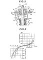
- a strut 10 in the Chapman's strut suspension shown in Figure 1, includes a cylindrical strut body 10a defining therein a hollow cylindrical chamber 10d.
- a shock absorber 12 is disposed within the chamber 10d and fixed to the strut 10.
- the shock absorber 12 has a thrusting piston 12b inserted into a hollow chamber 12c defined in an absorber cylinder 12a so that it can move axially in response to a shock applied to either a vehicle body 15 or a wheel 13.
- the piston 12b is connected to the vehicle body 15 by a strut rod 10b.
- the strut 10a is connected to a wheel spindle 14 in a per se well known manner.
- a suspension coil 11 surrounds the strut 10 and is disposed between upper and lower spring seats 22 and 21 respectively.
- the lower spring seat 21 is fitted to the outer periphery of the strut body and the upper spring seat 22 is fixed onto a bracket 16 secured onto the vehicle body 15.
- an expandable cover member 26 is disposed so that it surrounds the upper portion of the strut rod 10b.
- a bumper rubber 23 is fitted to the lower portion of the strut rod 10b so that it prevents the strut body 10a from colliding against the vehicle body.
- the wheel spindle 14 is also suspended onto a member 27 with a pair of transverse links 24 extending in parallel relationship with respect to each other.
- the member 27 is fixed to the vehicle body by fastening bolts 28. Further, the wheel spindle 14 is connected to the vehicle body 15 by a tension rod 25.
- the strut rod 10b has a small diameter top portion 10e having a threaded end 10f.
- a hollow cylindrical member 20 with upper and lower collars 20a and 20b is mounted on the portion 10e.
- a bushing 10g having a bowl-shaped upper piece 17 and a bowl-shaped lower piece 18 are provided to surround the member 20.
- the upper and lower pieces 17 and 18 of the bushing 10g are pre-loaded with the upper and lower collars 20a, 20b of the member 20.
- the member 20 is fixed at a shoulder 29 of the portion 10e by a fastening nut 19 engaging the threaded end 10f.
- An annular cylindrical member 30 with an inwardly depressed projection 31 extends circumferentially around the bushing 20.
- the projection 31 is inserted into a space between the upper piece 20a and the lower piece 20b to be sandwiched therebetween.
- a substantially disc- shaped member 32 with a central opening 33 engages the cylindrical member 30 by engagement of the circumferential edge of the opening 33 and a space 34 defined by the projection 31.
- the member 32 is secured onto the vehicle body 15 together with the bracket 16 by bolts 35 and nuts 36.
- the shock absorber 12 is provided with a damping characteristics such that a damping force is provided during the expansion stroke which is markedly larger than that in the compression stroke.
- the shock absorber 12 produces a substantially large damping force against a rebound shock and a relatively small damping force against a bounding shock.
- the large damping force against the rebound shock may reduce rolling in cornering, or pitching in acceleration or deceleration to provide better stability of driving.
- the upper and lower pieces 17 and 18 of the bushing 10g are formed of rubber having Rubber Hardness respectively HS65-75 and HS55-65.
- the upper piece 17 has a spring constant 15-25 kg/mm and the lower piece 18 has a spring constant 5-15 kg/mm, so that the sum of the spring constants of the upper and lower pieces are in a range 20-30 kg/mm.
- the shock absorbing characteristics can be improved as shown in Figure 3. If a relatively short stroke of bounding or rebound shock is applied, the shock absorber 12 will not cause the piston 12b to move due to friction between the piston 12b and the internal periphery of the piston chamber 12c, and due to viscosity of the working fluid to absorb the shock and serves as a rigid bar to transmit shock on the wheel 13 to the vehicle body via the bushing 10g. When a relatively short stroke of bound shock is applied, the strut rod 10a moves upwardly further compressing the lower piece 18 between the projection 31 and the collar 20b. At the same time, since the dimension between the projection 31 and the collar 20a is increased, the upper piece 17 can be released from the applied pre-load.
- the strut rod 10a moves downwardly with further compression of the upper piece 17 between the projection 31 and the collar 20a.
- the dimension between the projection 31 and the collar 20b is increased to release the lower piece 18 from pre-load.
- the damping force produced by the upper piece 17 is greater than that against the bounding shock, driving stability of the vehicle is increased. Namely, a relatively large damping force produced by the upper piece will work to stabilize rebound of the wheel in relation to the vehicle body in a relatively short period.
- Figure 3 shows resilient deformation of the bushing 10g relative to load applied to the bushing i.e. the damping force produced by the shock absorber 12.
- the solid line in Figure 3 shows a characteristic of resilient deformation of the bushing 10g in originally applied condition
- the chain line shows the resilient characteristics after vibrating 10' times with a load ⁇ 8 kg
- the broken line shows the resilient characteristics after vibrating 10 5 times with a load of 200 kg. It is thus apparent the deformation of the bushing 10g caused by rebound is smaller than that caused by bounding when the same load is applied. This means a larger damping force is produced against rebound.
Landscapes
- Engineering & Computer Science (AREA)
- Mechanical Engineering (AREA)
- General Engineering & Computer Science (AREA)
- Vehicle Body Suspensions (AREA)
Claims (6)
Applications Claiming Priority (2)
| Application Number | Priority Date | Filing Date | Title |
|---|---|---|---|
| JP54728/81 | 1981-04-11 | ||
| JP5472881A JPS57172806A (en) | 1981-04-11 | 1981-04-11 | Vehicle body fitting structure of suspension |
Publications (2)
| Publication Number | Publication Date |
|---|---|
| EP0063016A1 EP0063016A1 (fr) | 1982-10-20 |
| EP0063016B1 true EP0063016B1 (fr) | 1985-07-31 |
Family
ID=12978860
Family Applications (1)
| Application Number | Title | Priority Date | Filing Date |
|---|---|---|---|
| EP19820301753 Expired EP0063016B1 (fr) | 1981-04-11 | 1982-04-02 | Montage de suspension pour véhicule automobile |
Country Status (3)
| Country | Link |
|---|---|
| EP (1) | EP0063016B1 (fr) |
| JP (1) | JPS57172806A (fr) |
| DE (1) | DE3265011D1 (fr) |
Cited By (1)
| Publication number | Priority date | Publication date | Assignee | Title |
|---|---|---|---|---|
| DE19905693A1 (de) * | 1999-02-11 | 2000-09-07 | Mannesmann Sachs Ag | Schwingungsdämpfer |
Families Citing this family (10)
| Publication number | Priority date | Publication date | Assignee | Title |
|---|---|---|---|---|
| DE3302057A1 (de) * | 1983-01-22 | 1984-07-26 | Volkswagenwerk Ag, 3180 Wolfsburg | Karosserieseitige elastische lagerung eines federbeins |
| DE3445984A1 (de) * | 1984-12-18 | 1986-06-19 | Toyota Jidosha K.K., Toyota, Aichi | Luftfeder-radaufhaengung |
| US4779893A (en) * | 1987-09-24 | 1988-10-25 | General Motors Corporation | Strut type vehicle wheel suspension |
| FR2634425B1 (fr) * | 1988-07-20 | 1990-10-19 | Hutchinson | Dispositif superieur de liaison articulee entre un ensemble ressort-amortisseur et le chassis d'un vehicule automobile |
| US4883288A (en) * | 1988-10-20 | 1989-11-28 | General Motors Corporation | Suspension strut with side load support |
| US5158269A (en) * | 1990-10-11 | 1992-10-27 | Gencorp Inc. | Dual/slipper shock mount |
| DE4331585C2 (de) * | 1992-09-23 | 2002-06-20 | Volkswagen Ag | Oberes Stützlager für einen Federdämpfer oder ein Federbein |
| EP2110273B1 (fr) * | 2008-04-18 | 2013-03-27 | Fiat Group Automobiles S.p.A. | Support en matière élastique pour la fixation supérieure d'un amortisseur de suspension d'un véhicule automobile |
| WO2012011386A1 (fr) * | 2010-07-20 | 2012-01-26 | 本田技研工業株式会社 | Structure de montage pour amortisseur de véhicule |
| JP5400980B1 (ja) * | 2013-03-29 | 2014-01-29 | 株式会社ショーワ | 懸架装置、サスペンションサポート、および緩衝部材 |
Family Cites Families (6)
| Publication number | Priority date | Publication date | Assignee | Title |
|---|---|---|---|---|
| GB1238641A (fr) * | 1967-05-01 | 1971-07-07 | ||
| DE1911127A1 (de) * | 1969-03-05 | 1970-09-17 | Porsche Kg | Abstuetzung eines aus Stossdaempfer und Haupttragfeder bestehenden Federaggregates fuer Kraftfahrzeuge |
| NL155342B (nl) * | 1974-02-05 | 1977-12-15 | Itt | Veereenheid voor een af te veren systeem. |
| DE2433583C2 (de) * | 1974-07-12 | 1983-12-22 | Volkswagenwerk Ag, 3180 Wolfsburg | Aufhängung der lenkbaren Räder eines Kraftfahrzeuges |
| FR2319813A1 (fr) * | 1975-08-01 | 1977-02-25 | Renault | Element elastique de fixation d'amortisseur porteur |
| JPS55140607A (en) * | 1979-04-18 | 1980-11-04 | Nissan Motor Co Ltd | Strut-type suspender |
-
1981
- 1981-04-11 JP JP5472881A patent/JPS57172806A/ja active Pending
-
1982
- 1982-04-02 EP EP19820301753 patent/EP0063016B1/fr not_active Expired
- 1982-04-02 DE DE8282301753T patent/DE3265011D1/de not_active Expired
Cited By (2)
| Publication number | Priority date | Publication date | Assignee | Title |
|---|---|---|---|---|
| DE19905693A1 (de) * | 1999-02-11 | 2000-09-07 | Mannesmann Sachs Ag | Schwingungsdämpfer |
| DE19905693C2 (de) * | 1999-02-11 | 2003-09-18 | Zf Sachs Ag | Schwingungsdämpfer |
Also Published As
| Publication number | Publication date |
|---|---|
| DE3265011D1 (en) | 1985-09-05 |
| EP0063016A1 (fr) | 1982-10-20 |
| JPS57172806A (en) | 1982-10-23 |
Similar Documents
| Publication | Publication Date | Title |
|---|---|---|
| US4434977A (en) | Strut type suspension for a vehicle | |
| EP0065235B2 (fr) | Suspension du type à jambe de forces | |
| US4478396A (en) | Elastic support structure of wheel suspension mechanism | |
| US20060043659A1 (en) | Dual spring jounce bumper assembly | |
| EP0105232A1 (fr) | Jambe de suspension pour un véhicule automobile | |
| US5330166A (en) | Upper mounting structure for a wheel suspension | |
| US6155543A (en) | Spring seat assembly for an automotive vehicle | |
| US5251928A (en) | Upper mounting structure for a strut-type wheel suspension | |
| US3263983A (en) | Shock absorber and auxiliary spring unit | |
| GB2037934A (en) | Suspension strut assemblies | |
| CA1263413A (fr) | Dispositif pour ressorts helicoidaux de vehicules automobiles | |
| EP0182607A2 (fr) | Système à double butée de débattement | |
| EP0063016A1 (fr) | Montage de suspension pour véhicule automobile | |
| US3572678A (en) | Overload spring structure | |
| US4210343A (en) | Automotive suspension system | |
| US5005855A (en) | Insulator device for strut type suspension system of automobile | |
| US2999678A (en) | Auxiliary spring suspensions | |
| JP3874385B2 (ja) | フロントフォーク | |
| JPH03244844A (ja) | エアサスペンション | |
| JPH0139202Y2 (fr) | ||
| JP2935128B2 (ja) | サスペンション装置のマウント | |
| JPH0311042Y2 (fr) | ||
| JPH0311468Y2 (fr) | ||
| JPH06122308A (ja) | ストラットサスペンション装置 | |
| JPS6326306Y2 (fr) |
Legal Events
| Date | Code | Title | Description |
|---|---|---|---|
| PUAI | Public reference made under article 153(3) epc to a published international application that has entered the european phase |
Free format text: ORIGINAL CODE: 0009012 |
|
| 17P | Request for examination filed |
Effective date: 19820413 |
|
| AK | Designated contracting states |
Designated state(s): DE FR GB IT |
|
| ITF | It: translation for a ep patent filed | ||
| GRAA | (expected) grant |
Free format text: ORIGINAL CODE: 0009210 |
|
| RAP1 | Party data changed (applicant data changed or rights of an application transferred) |
Owner name: NISSAN MOTOR CO., LTD. |
|
| AK | Designated contracting states |
Designated state(s): DE FR GB IT |
|
| REF | Corresponds to: |
Ref document number: 3265011 Country of ref document: DE Date of ref document: 19850905 |
|
| ET | Fr: translation filed | ||
| PLBE | No opposition filed within time limit |
Free format text: ORIGINAL CODE: 0009261 |
|
| STAA | Information on the status of an ep patent application or granted ep patent |
Free format text: STATUS: NO OPPOSITION FILED WITHIN TIME LIMIT |
|
| 26N | No opposition filed | ||
| GBPC | Gb: european patent ceased through non-payment of renewal fee | ||
| PG25 | Lapsed in a contracting state [announced via postgrant information from national office to epo] |
Ref country code: GB Effective date: 19881121 |
|
| PG25 | Lapsed in a contracting state [announced via postgrant information from national office to epo] |
Ref country code: FR Free format text: LAPSE BECAUSE OF NON-PAYMENT OF DUE FEES Effective date: 19881229 |
|
| PG25 | Lapsed in a contracting state [announced via postgrant information from national office to epo] |
Ref country code: DE Effective date: 19890103 |
|
| REG | Reference to a national code |
Ref country code: FR Ref legal event code: ST |