EP0063057A1 - Verfahren zum Messen des Parallelismus der Räder der Vorder- und Hinterwelle von Kraftwagen sowie der Rückstellwinkel zwischen den Vorderrädern und der Krabwinkel und Gerät zum Ausführen dieses Verfahrens - Google Patents
Verfahren zum Messen des Parallelismus der Räder der Vorder- und Hinterwelle von Kraftwagen sowie der Rückstellwinkel zwischen den Vorderrädern und der Krabwinkel und Gerät zum Ausführen dieses Verfahrens Download PDFInfo
- Publication number
- EP0063057A1 EP0063057A1 EP82400003A EP82400003A EP0063057A1 EP 0063057 A1 EP0063057 A1 EP 0063057A1 EP 82400003 A EP82400003 A EP 82400003A EP 82400003 A EP82400003 A EP 82400003A EP 0063057 A1 EP0063057 A1 EP 0063057A1
- Authority
- EP
- European Patent Office
- Prior art keywords
- angle
- parallelism
- wheel
- axis
- front wheel
- Prior art date
- Legal status (The legal status is an assumption and is not a legal conclusion. Google has not performed a legal analysis and makes no representation as to the accuracy of the status listed.)
- Granted
Links
- 238000000034 method Methods 0.000 title claims description 35
- 230000003068 static effect Effects 0.000 claims abstract description 5
- 238000006073 displacement reaction Methods 0.000 claims abstract description 4
- 238000005259 measurement Methods 0.000 claims description 7
- 230000000007 visual effect Effects 0.000 claims description 3
- 238000010586 diagram Methods 0.000 description 4
- 240000008042 Zea mays Species 0.000 description 3
- 238000003491 array Methods 0.000 description 2
- 241000238557 Decapoda Species 0.000 description 1
- 241000135309 Processus Species 0.000 description 1
- 241001080024 Telles Species 0.000 description 1
- 208000006379 syphilis Diseases 0.000 description 1
Images


Classifications
-
- G—PHYSICS
- G01—MEASURING; TESTING
- G01B—MEASURING LENGTH, THICKNESS OR SIMILAR LINEAR DIMENSIONS; MEASURING ANGLES; MEASURING AREAS; MEASURING IRREGULARITIES OF SURFACES OR CONTOURS
- G01B11/00—Measuring arrangements characterised by the use of optical techniques
- G01B11/26—Measuring arrangements characterised by the use of optical techniques for measuring angles or tapers; for testing the alignment of axes
- G01B11/275—Measuring arrangements characterised by the use of optical techniques for measuring angles or tapers; for testing the alignment of axes for testing wheel alignment
- G01B11/2755—Measuring arrangements characterised by the use of optical techniques for measuring angles or tapers; for testing the alignment of axes for testing wheel alignment using photoelectric detection means
-
- G—PHYSICS
- G01—MEASURING; TESTING
- G01B—MEASURING LENGTH, THICKNESS OR SIMILAR LINEAR DIMENSIONS; MEASURING ANGLES; MEASURING AREAS; MEASURING IRREGULARITIES OF SURFACES OR CONTOURS
- G01B2210/00—Aspects not specifically covered by any group under G01B, e.g. of wheel alignment, caliper-like sensors
- G01B2210/10—Wheel alignment
- G01B2210/28—Beam projector and related sensors, camera, inclinometer or other active sensing or projecting device
- G01B2210/283—Beam projectors and related sensors
Definitions
- the present invention relates to a method for measuring the parallelism of the wheels of the front and rear axles of motor vehicles, the "set-back" angles between the wheels of the front axle, the crab angle of the vehicle as well as other angular parameters useful for vehicle control.
- the invention also relates to an apparatus for implementing this process.
- the object of the invention is to propose a method and an apparatus for implementing this method, which do not have the drawbacks of known embodiments, and which therefore make it possible to quickly and precisely execute a series of angular measurements relating to the front and rear axles as well as other parameters of a vehicle, with a moderate cost price.
- the thrust axis of a vehicle being defined as the bisector of the angle formed by the median vertical planes of the rear wheels of the latter, the dynamic angle called “set-back” is called the apex with the center of each front wheel and having as sides, on the one hand the straight line joining the centers of the front wheels and on the other hand, the perpendicular to the thrust axis of the vehicle.
- the right front parallelism angle as a function of the thrust axis of the vehicle will be considered below by convention as positive if there is a pinch with respect to the thrust axis, and the angle of front left parallelism as a function of the thrust axis of the vehicle will also be considered positive if there is a pinch in relation to the thrust axis.
- the abovementioned angular values are determined in an electronic computer by the following relationships, established geometrically: and one makes permanently determine by the computer the values of the individual parallelism ⁇ 1n of the right front wheel and ⁇ 2n of the left front wheel at times "n" according to the relations these values being displayed so that they can be viewed by the operator, who then adjusts the parallelism of the front wheels to the desired values.
- the method according to the invention makes it possible, only from the measurement of the angles between the reference line and the perpendicular to each associated arm and by application of the above relationships which are demonstrated geometrically, to measure with precision the series of the aforementioned parameters, that is to say the angles of parallelism of the front wheels, of the rear wheels as a function of the thrust axis, in particular when the front parallelism is centered relative to the center point of the direction as well as when it is equally distributed with respect to the thrust axis, and the dynamic set-back angle.
- the apparatus for implementing the above method comprises, according to the invention, an arm fixed laterally to each front wheel and on each arm of the means for materializing a reference line connecting two fixed points located on the arms, a transmitter 'A light brush parallel to the plane of the corresponding front wheel and directed towards the rear wheel located on the same side, and a mirror carried by said rear wheel to reflect the light brush on a photosensitive cell mounted on the corresponding arm.
- the means for materializing the reference line may consist of angular sensors arranged on the front ends of the arms and forming the fixed points, these sensors being connected by a tensioning wire and may for example be constituted by potentiometers making it possible to take up the angles of front axle parallelism.
- the process and the apparatus according to the invention make it possible, as we see, to determine a whole series of interesting angular values for the vehicle and to control this as a function of the tolerance ranges given for each vehicle, thanks to the visual display of the results obtained by the calculator, using only two angular measurements and using relatively inexpensive equipment.
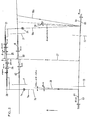
- FIG. 1 there is an apparatus for implementing a method according the invention, to measure the parallelism of the wheels of the front and rear trains of motor vehicles as a function of the thrust axis of the vehicle, as well as the angle of "set-back" between the wheels of the front axle.
- the thrust axis of a vehicle is the bisector of the angle formed by the rear wheels thereof;
- the dynamic set-back angle is the angle whose apex is the center of the one of the front wheels and which has the sides of a straight line joining the centers of the front wheels and secondly perpendicular to the thrust axis of the vehicle, as will be seen from the drawings below.
- the apparatus covered by the invention comprises an arm (3; 4) fixed laterally to each respective front wheel (1, 2) and on each arm (3, 4) means are provided to materialize a reference line 9 connecting two fixed points (20, 21) located on the arms (3, 4) respectively.
- the apparatus also comprises, placed on each arm (3, 4), a transmitter (22,5) respectively of a light brush (7a, 18a) parallel to the plane of the corresponding front wheel (1, 2), and directed towards the rear wheel (13, 15) located on the same side.
- the latter carries a mirror (8,12) for reflecting the light brush (7a, 18a), constituted by a line parallel to the median plane of the corresponding front wheel on a photosensitive cell (14,24) mounted on the respective arm (3 , 4) horizontal
- the front wheels (1, 2) of the vehicle are brought on pivoting plates (16, 17), and the arms (3, 4) are carried by the rim of the associated wheel (1, 2) by means of an attachment device (6) known per se and which will therefore not be described here.
- the means for materializing the reference line 9 are constituted by the combination of a tensioning wire 9, the ends of which are fixed to the front end portions of the horizontal arms (3, 4), and by two angular sensors (20, 21) carried respectively by the arms (3, 4). These sensors can for example be potentiometers, connected by the tensioning wire 9.
- Each mirror (8, 12) is placed perpendicular to the plane of the corresponding rear wheel (13, 15), the reflected light line being returned towards the photosensitive cell (14, 24).
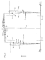
- ⁇ 1 and ⁇ 2 be the angles delivered respectively by the right front sensor 21 and the left front sensor 20:
- ⁇ 11 is the angle between the right of reference 11 and the perpendicular 25 to the arms 4 plotted from the corresponding fixed point 21,
- ⁇ 21 being the angle between the straight line 9 and the perpendicular 26 to the arms 3 plotted from the corresponding fixed point 20.
- angles ⁇ 11 and ⁇ 21 shown in FIG. 2 are measured respectively by the sensors 21 and 20, and are considered by convention to be positive when the arm (4, 3) and the tensioner 9 form an obtuse angle, which is the case in Figure 2. (Of course, we could adopt a contrary convention).
- the thrust axis of the vehicle is designated by the reference 27, while the straight lines 28 and 29 are parallel to the thrust axis 27, drawn from the points of impact of the light lines (7a, 18a) on the corresponding mirrors (8, 12).
- ⁇ 1 is the right front parallelism angle as a function of the thrust axis 27 (positive, if it corresponds to a pinch, negative if it corresponds to an opening of the wheel).
- this angle ⁇ 1 ( ⁇ 11 in Figure 2 and ⁇ 12 in Figure 3) is the angle between the line 25 perpendicular to the vertical plane containing the light beam 18a drawn from the fixed point 21, and the perpendicular to the axis 27 also drawn from point 21.
- 9 2 is the front left parallelism angle as a function of the thrust axis 27 (positive if it corresponds to a pinch and negative if it corresponds to an opening).
- this angle ⁇ 2 ( ⁇ 21 in Figure 2 and ⁇ 22 in Figure 3) is the angle entre'la line 26 perpendicular to the vertical plane containing the light beam 7a, plotted from the fixed point 20, and the perpendicular to the axis 27 plotted from point 20.
- the second indices assigned to the different angles represent the successive times corresponding to FIGS. 5, 2 and 3, on which the respective angles have therefore been plotted ⁇ 10 (negative), ⁇ 20 (positive), ⁇ 10 (positive), ⁇ 20 ( positive), ⁇ 11 (positive), ⁇ 2i (positive), ⁇ 11 (positive), ⁇ 21 (negative); ⁇ 12 (negative), ⁇ 22 (positive), ⁇ 12 (negative) and ⁇ 22 (positive).
- the dynamic set-back angle of the vehicle is the angle with the apex of the center of each front wheel (1, 2) and for sides, on the one hand, the straight line 60 ( Figure 2 ) joining the centers of the front wheels (1, 2), and on the other hand, the perpendicular (61, 62) to the thrust axis 27, traced from the center of the front wheel (2, 1).
- This angle is positive when the right front wheel 2 is in front of the left front wheel 1, as is the case in FIGS. 2 to 5.
- the operating mode of the method according to the invention essentially consists in reading by means of the angular sensors (21, 20) the angles ⁇ 1 and ⁇ 2 successively in the situation of FIG. 2 and that of FIG. 3, in order to obtain ⁇ 11 and ⁇ 21 in the first position, then ⁇ 12 and ⁇ 22 in the second position. From four angles thus noted, geometrically determined and successively calculated in an electronic computer forming part of the apparatus. according to the invention, but not shown:
- ⁇ 13 ⁇ 23 physically represents the individual angle of dynamic parallelism of each of the front wheels (2, 1), that is to say when the front parallelism is distributed with respect to the thrust axis 27, which corresponds to real parallelism on the road when the driver releases the steering wheel.
- the computer can then calculate the values of the individual parallelism ⁇ 10 and ⁇ 20 of the front wheels as a function of the thrust axis 27, when the direction is at its point of mechanical center.
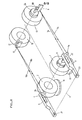
- This process can also be applied to indicate. to the operator the steering direction in order to obtain the configuration corresponding to the dynamic parallelism of the vehicle, that is to say the state corresponding to FIG. 4.
- This allows the operator to know the position of the steering wheel and from the center point of the steering when it releases the steering wheel on the road.
- the device indicates to the operator the turning direction, then the exact position satisfying the following relationships:
- This position of the steering wheel is that which therefore corresponds to the situation in FIG. 4.
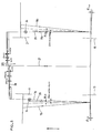
- the apparatus illustrated in FIG. 8 comprises, associated with each rear wheel (13, 15), a photosensitive cell (30, 31) respectively mounted above the corresponding mirror (8, 12) at a distance a from the median plane of each wheel (13, 15) equal for the two wheels.
- the line 7a strikes the left rear cell 30, while the light line 18a strikes a point situated beyond the right rear cell 31, this situation being reversed in FIG. 7.
- the vehicle shown diagrammatically in these figures has on the other hand the front track 2e greater than the rear track 2h, and the front axle 1, 2 offset on the right with respect to the rear axle (13, 15).
- the straight line 32 is the axis of symmetry of the vehicle, that is to say the straight line joining the midpoints of the two axles.
- the lines 33 and 34 are parallels to the axis of symmetry 32, passing respectively through the points of impact of the light lines 7a and 18a.
- ⁇ 24 angle of parallelism of the left front wheel (1) relative to the thrust axis (27) when the light line (7a) hits the left rear cell (30) (FIG. 6),
- ⁇ 24 value of the angle ⁇ 2 of the left front wheel (1) when the light line (7a) hits the left rear cell (30) (FIG. 6),
- ⁇ 14 angle of parallelism of the right front wheel (2) relative to the thrust axis (27) when one is in the case of Figure 6.
- ⁇ 14 value of the angle ⁇ 1 of the right front wheel (2), when we are in the case of Figure 6.
- ⁇ 15 angle of parallelism of the right front wheel (2) relative to the thrust axis (27) when the light line (18a) hits the right rear cell (31) (FIG. 7),
- ⁇ 15 value of the angle ⁇ 1 for the right front wheel (2) when the light line (18a) hits the right rear cell (31),
- ⁇ 25 angle of parallelism of the left front wheel (1) relative to the thrust axis 27 when we are in the case of FIG. 7,
- vehicle crab angle that is to say the angle having sides, on the one hand the thrust axis (27) and on the other hand the axis of symmetry (32) of the vehicle,
- ⁇ 1 front right parallelism angle as a function of the axis of symmetry (32),
- ⁇ 2 front left parallelism angle as a function of the axis of symmetry (32),
- ⁇ 10 front right parallelism angle with respect to the axis of symmetry (32) when the direction is at its point of mechanical center,
- ⁇ 13 dynamic front parallelism angle with respect to the axis of symmetry (32),
- ⁇ 23 front left dynamic parallelism angle with respect to the axis of symmetry (32),
- ⁇ 1 rear right parallelism angle as a function of the axis of symmetry (32) ( Figure 6),
- ⁇ 2 rear left parallelism angle as a function of the axis of symmetry (32).
- the straight line 35a is perpendicular to the axis of symmetry 32 carried from the front end of the right front arm 4, that is to say from the fixed point 21.
- the device can display the following results at the end of the second control phase :
- the invention is not limited to the operating sequences described.
- the means for materializing the reference line 9 can be constituted by two projectors placed each at the front end of the arm (3, 4) and which emit a light beam striking a target placed on the end of the other arm. So we can consider on each arm a fixed beam directed at right angles to the support arm of the transmitter, towards a diode array placed on the opposite arm and thus determine the values ⁇ 1 and ⁇ 2 , or else a mobile beam performing a scan constant, associated with a fixed receiver. Indeed, the physical connection between the arms 3, 4, constituted by the tensioner 9, is not necessary.
- the cells 14, 24 are preferably, but not necessarily, positioned in the vertical plane of the respective beam (7a, 18a). In case they are not placed in these vertical planes, a correction should. be introduced.
- the distances a between cells 30 and 31 and the median planes of the rear wheels are not necessarily equal between the front axle and the rear axle (FIG. 6).
- the method and the apparatus for implementation according to the invention therefore make it possible, from the measurement of two basic angular values ⁇ 1 and ⁇ 2 , and in the different configurations of the wheels described above, to determine by means of the computer a whole series of angular parameters of the vehicle, and of adjusting these continuously by means of a display of the results obtained by the computer.
- These values are calculated extremely precisely, and it should be emphasized that the system for implementing this method is relatively inexpensive compared with certain known systems, in particular those using laser emitters and diode arrays.
Landscapes
- Physics & Mathematics (AREA)
- General Physics & Mathematics (AREA)
- Length Measuring Devices With Unspecified Measuring Means (AREA)
- Length Measuring Devices By Optical Means (AREA)
Priority Applications (1)
| Application Number | Priority Date | Filing Date | Title |
|---|---|---|---|
| AT82400003T ATE22725T1 (de) | 1981-01-20 | 1982-01-05 | Verfahren zum messen des parallelismus der raeder der vorder- und hinterwelle von kraftwagen sowie der rueckstellwinkel zwischen den vorderraedern und der krabwinkel und geraet zum ausfuehren dieses verfahrens. |
Applications Claiming Priority (2)
| Application Number | Priority Date | Filing Date | Title |
|---|---|---|---|
| FR8100944 | 1981-01-20 | ||
| FR8100944A FR2498315B1 (fr) | 1981-01-20 | 1981-01-20 | Procede pour mesurer le parallelisme des ro ues des trains avant et arriere de vehicules automobiles ainsi que les angles de set-back entre les roues du train avant et l'angle de crabe, et appareillage pour la mise en oeuvre de ce procede |
Publications (2)
| Publication Number | Publication Date |
|---|---|
| EP0063057A1 true EP0063057A1 (de) | 1982-10-20 |
| EP0063057B1 EP0063057B1 (de) | 1986-10-08 |
Family
ID=9254311
Family Applications (1)
| Application Number | Title | Priority Date | Filing Date |
|---|---|---|---|
| EP82400003A Expired EP0063057B1 (de) | 1981-01-20 | 1982-01-05 | Verfahren zum Messen des Parallelismus der Räder der Vorder- und Hinterwelle von Kraftwagen sowie der Rückstellwinkel zwischen den Vorderrädern und der Krabwinkel und Gerät zum Ausführen dieses Verfahrens |
Country Status (5)
| Country | Link |
|---|---|
| US (1) | US4455759A (de) |
| EP (1) | EP0063057B1 (de) |
| AT (1) | ATE22725T1 (de) |
| DE (1) | DE3273650D1 (de) |
| FR (1) | FR2498315B1 (de) |
Cited By (3)
| Publication number | Priority date | Publication date | Assignee | Title |
|---|---|---|---|---|
| EP0319837A3 (en) * | 1987-11-30 | 1990-04-25 | Mazda Motor Corporation | A method for toe angle adjustment and a toe angle adjusting apparatus |
| GB2358709A (en) * | 2000-01-25 | 2001-08-01 | Supertracker Ltd | Wheel alignment apparatus |
| US8197147B2 (en) | 2006-09-13 | 2012-06-12 | Edith Cowan University | Optical connection component |
Families Citing this family (20)
| Publication number | Priority date | Publication date | Assignee | Title |
|---|---|---|---|---|
| US4594789A (en) * | 1985-04-22 | 1986-06-17 | Bear Automotive Service Equipment Company | Wheel alignment system |
| JPH0747683Y2 (ja) * | 1987-04-27 | 1995-11-01 | 三菱自動車工業株式会社 | 操向輪の舵角検出装置 |
| EP0440365B1 (de) * | 1990-01-25 | 1995-06-21 | Mitsubishi Jidosha Kogyo Kabushiki Kaisha | Verfahren und Vorrichtung zum Feststellen des Lenkausschlagnullpunktes eines Fahrzeuges |
| US5207002A (en) * | 1992-03-19 | 1993-05-04 | Humblet Steven V | Method and system for vehicle frame alignment |
| US5675515A (en) * | 1995-12-28 | 1997-10-07 | Hunter Engineering Company | Apparatus and method for determining vehicle wheel alignment measurements from three dimensional wheel positions and orientations |
| US6438855B1 (en) | 2001-01-11 | 2002-08-27 | Mark C. Bremer | Portable wheel alignment system for motorcycles |
| US6522400B1 (en) * | 2001-06-18 | 2003-02-18 | Edward Horn | Portable front wheel alignment apparatus and method |
| US6745483B2 (en) * | 2002-06-21 | 2004-06-08 | Deere & Company | Vehicle wheel toe-in alignment apparatus and method |
| US20050005461A1 (en) * | 2003-06-25 | 2005-01-13 | Henry Rohrig | Truck alignment system |
| US6823598B1 (en) * | 2003-09-30 | 2004-11-30 | Michael C. Loescher | Laser supporting attachment for vehicle alignment system |
| US7502675B2 (en) * | 2004-04-01 | 2009-03-10 | Delphi Technologies, Inc. | Feedforward control of motor vehicle roll angle |
| US7191047B2 (en) * | 2004-09-27 | 2007-03-13 | Delphi Technologies, Inc. | Motor vehicle control using a dynamic feedforward approach |
| US7252301B2 (en) * | 2005-02-02 | 2007-08-07 | Brp Finland Oy | Snowmobile ski with alignment points |
| US7383636B2 (en) * | 2005-10-31 | 2008-06-10 | Chief Automotive Technologies, Inc. | Tracking attachment |
| US9477978B1 (en) * | 2008-04-04 | 2016-10-25 | United Services Automobile Association | Systems and methods for a virtual car advisor |
| EP2131146A1 (de) * | 2008-06-02 | 2009-12-09 | Saab Ab | Positionierung eines lichtreflektierenden Objekts durch das Schwenken von linienförmigen Lichtstrahlen |
| IT1399988B1 (it) * | 2010-05-05 | 2013-05-09 | Space S R L Con Unico Socio | Sistema, e relativo metodo, di determinazione dell'allineamento delle ruote di un veicolo |
| TWM513550U (zh) * | 2015-06-26 | 2015-12-01 | Senseage Co Ltd | 支撐板 |
| US10274315B2 (en) * | 2016-11-09 | 2019-04-30 | Hall Labs Llc | Three-wheeled vehicle alignment rack system |
| CN114088366B (zh) * | 2021-11-03 | 2024-05-03 | 长春富维汽车视镜系统有限公司 | 一种汽车后视镜折叠耐久试验装置 |
Citations (7)
| Publication number | Priority date | Publication date | Assignee | Title |
|---|---|---|---|---|
| FR2343221A1 (fr) * | 1976-03-01 | 1977-09-30 | Applied Power Inc | Appareil de mesure des relations d'angle des roues de vehicules |
| FR2382675A1 (fr) * | 1977-03-02 | 1978-09-29 | Fmc Corp | Appareil de mesure des angles de pincement ou d'ouverture des roues avant d'un vehicule a moteur |
| US4126943A (en) * | 1977-05-20 | 1978-11-28 | Hunter Engineering Company | Wheel alignment apparatus and method |
| FR2451020A1 (fr) * | 1979-03-09 | 1980-10-03 | Muller Et Cie Ets | Procede pour controler le parallelisme des roues des trains avant et arriere de vehicules automobiles et appareil pour la mise en oeuvre de ce procede |
| US4239389A (en) * | 1978-12-06 | 1980-12-16 | Hunter Engineering Company | Vehicle wheel and body alignment diagnosing system |
| WO1981000909A1 (en) * | 1979-10-01 | 1981-04-02 | Hunter Eng Co | Vehicle wheel alignment apparatus |
| WO1981001047A1 (en) * | 1979-10-02 | 1981-04-16 | L Hunter | Vehicle wheel alignment apparatus |
Family Cites Families (2)
| Publication number | Priority date | Publication date | Assignee | Title |
|---|---|---|---|---|
| US4106208A (en) * | 1976-04-09 | 1978-08-15 | Lee Hunter | Method of and apparatus for determining vehicle wheel alignment |
| US4130362A (en) * | 1977-09-19 | 1978-12-19 | Fmc Corporation | Apparatus for determining steering positions of the front wheels of a vehicle |
-
1981
- 1981-01-20 FR FR8100944A patent/FR2498315B1/fr not_active Expired
-
1982
- 1982-01-05 EP EP82400003A patent/EP0063057B1/de not_active Expired
- 1982-01-05 AT AT82400003T patent/ATE22725T1/de not_active IP Right Cessation
- 1982-01-05 DE DE8282400003T patent/DE3273650D1/de not_active Expired
- 1982-01-19 US US06/340,694 patent/US4455759A/en not_active Expired - Fee Related
Patent Citations (7)
| Publication number | Priority date | Publication date | Assignee | Title |
|---|---|---|---|---|
| FR2343221A1 (fr) * | 1976-03-01 | 1977-09-30 | Applied Power Inc | Appareil de mesure des relations d'angle des roues de vehicules |
| FR2382675A1 (fr) * | 1977-03-02 | 1978-09-29 | Fmc Corp | Appareil de mesure des angles de pincement ou d'ouverture des roues avant d'un vehicule a moteur |
| US4126943A (en) * | 1977-05-20 | 1978-11-28 | Hunter Engineering Company | Wheel alignment apparatus and method |
| US4239389A (en) * | 1978-12-06 | 1980-12-16 | Hunter Engineering Company | Vehicle wheel and body alignment diagnosing system |
| FR2451020A1 (fr) * | 1979-03-09 | 1980-10-03 | Muller Et Cie Ets | Procede pour controler le parallelisme des roues des trains avant et arriere de vehicules automobiles et appareil pour la mise en oeuvre de ce procede |
| WO1981000909A1 (en) * | 1979-10-01 | 1981-04-02 | Hunter Eng Co | Vehicle wheel alignment apparatus |
| WO1981001047A1 (en) * | 1979-10-02 | 1981-04-16 | L Hunter | Vehicle wheel alignment apparatus |
Cited By (4)
| Publication number | Priority date | Publication date | Assignee | Title |
|---|---|---|---|---|
| EP0319837A3 (en) * | 1987-11-30 | 1990-04-25 | Mazda Motor Corporation | A method for toe angle adjustment and a toe angle adjusting apparatus |
| GB2358709A (en) * | 2000-01-25 | 2001-08-01 | Supertracker Ltd | Wheel alignment apparatus |
| GB2358709B (en) * | 2000-01-25 | 2003-03-05 | Supertracker Ltd | Wheel alignment apparatus |
| US8197147B2 (en) | 2006-09-13 | 2012-06-12 | Edith Cowan University | Optical connection component |
Also Published As
| Publication number | Publication date |
|---|---|
| US4455759A (en) | 1984-06-26 |
| DE3273650D1 (en) | 1986-11-13 |
| EP0063057B1 (de) | 1986-10-08 |
| FR2498315B1 (fr) | 1986-04-04 |
| ATE22725T1 (de) | 1986-10-15 |
| FR2498315A1 (fr) | 1982-07-23 |
Similar Documents
| Publication | Publication Date | Title |
|---|---|---|
| EP0063057A1 (de) | Verfahren zum Messen des Parallelismus der Räder der Vorder- und Hinterwelle von Kraftwagen sowie der Rückstellwinkel zwischen den Vorderrädern und der Krabwinkel und Gerät zum Ausführen dieses Verfahrens | |
| EP0015826B1 (de) | Verfahren zur Überprüfung der Parallelität der Räder des Vorder- und Hinterradgestells von Kraftfahrzeugen und Vorrichtung zur Durchführung des Verfahrens | |
| EP0948760B1 (de) | Verfahren zur messung der position und der ausrichtung von einer oder mehreren bewegten kameras | |
| EP0279730B1 (de) | Vorrichtung und Verfahren für dreidimensionale Vermessung | |
| FR2565356A1 (fr) | Moyens pour guider un vehicule | |
| EP2199874A1 (de) | Holografischer Sensor und Bildanzeigesystem zur Fernerkennung eines Objekts | |
| FR2566897A1 (fr) | Appareil pour controler l'alignement des roues d'un vehicule | |
| FR2711424A1 (fr) | Appareil et procédé de mesure d'alignement des roues à étalonnage automatique. | |
| WO1990008939A1 (fr) | Procede d'etalonnage d'un systeme d'acquisition tridimensionnelle de forme et systeme pour la mise en oeuvre dudit procede | |
| EP1019747B1 (de) | Verfahren zur korrektur von durch antennenschwankungen hervorgerufenen störeffekten für ein sonargerät mit synthetischer antenne | |
| FR2755759A1 (fr) | Procede, ensemble et appareil de mesure des angles caracteristiques des roues d'un vehicule | |
| FR2676544A1 (fr) | Systeme pour detecter la position d'un corps mobile. | |
| EP0757231B1 (de) | Vorrichtung zur Vermessung und geometrischen Kontrolle von Kraftfahrzeugen | |
| FR2748321A1 (fr) | Dispositif pour le controle geometrique de vehicule | |
| EP0778958B1 (de) | Vorrichtung zum ausrichten eines beobachtungsinstrumentes | |
| EP3488380B1 (de) | Verfahren zum bestimmen einer blendungshöhe für einen kraftfahrzeugführer | |
| EP0733226B1 (de) | Orientierungskorrektursystem für beobachtungsgerät | |
| FR2697081A1 (fr) | Codeur à large étendue de mesure, destiné à la détermination de la position d'une pièce dans une course d'amplitude prédéterminée, telle qu'un accessoire de véhicule. | |
| WO1989007750A1 (fr) | Procede de numerisation de la surface d'un objet tridimensionnel et appareil de releve en vue de sa mise en oeuvre | |
| FR2732493A1 (fr) | Dispositif de detection et/ou de localisation d'un vehicule | |
| EP3865816B1 (de) | Verfahren und systeme zur fernmessung der winkelausrichtung eines fahrzeugs innerhalb eines kraftfahrzeugkonvois auf der strasse. | |
| EP1391686A1 (de) | Verfahren und Vorrichtung zur Lokalisierung von Objekten mittels einer optischen Messtechnik | |
| EP0669535B1 (de) | Verfahren und Vorrichtung zur Messung der relativen Lageveränderung zwischen zwei Bauteilen | |
| FR3111464A1 (fr) | Procédé de calibration d’une caméra et dispositif associé | |
| FR2545613A1 (fr) | Appareil de mesure de la vitesse d'un objet, notamment d'un aeronef |
Legal Events
| Date | Code | Title | Description |
|---|---|---|---|
| PUAI | Public reference made under article 153(3) epc to a published international application that has entered the european phase |
Free format text: ORIGINAL CODE: 0009012 |
|
| AK | Designated contracting states |
Designated state(s): AT BE CH DE GB IT LU NL SE |
|
| 17P | Request for examination filed |
Effective date: 19830407 |
|
| ITF | It: translation for a ep patent filed | ||
| GRAA | (expected) grant |
Free format text: ORIGINAL CODE: 0009210 |
|
| AK | Designated contracting states |
Kind code of ref document: B1 Designated state(s): AT BE CH DE GB IT LI LU NL SE |
|
| PG25 | Lapsed in a contracting state [announced via postgrant information from national office to epo] |
Ref country code: NL Effective date: 19861008 Ref country code: AT Effective date: 19861008 |
|
| REF | Corresponds to: |
Ref document number: 22725 Country of ref document: AT Date of ref document: 19861015 Kind code of ref document: T |
|
| PG25 | Lapsed in a contracting state [announced via postgrant information from national office to epo] |
Ref country code: SE Effective date: 19861031 |
|
| REF | Corresponds to: |
Ref document number: 3273650 Country of ref document: DE Date of ref document: 19861113 |
|
| PG25 | Lapsed in a contracting state [announced via postgrant information from national office to epo] |
Ref country code: LU Free format text: LAPSE BECAUSE OF NON-PAYMENT OF DUE FEES Effective date: 19870131 Ref country code: LI Effective date: 19870131 Ref country code: CH Effective date: 19870131 |
|
| NLV1 | Nl: lapsed or annulled due to failure to fulfill the requirements of art. 29p and 29m of the patents act | ||
| BERE | Be: lapsed |
Owner name: ETS M. MULLER & CIE Effective date: 19870131 |
|
| PLBE | No opposition filed within time limit |
Free format text: ORIGINAL CODE: 0009261 |
|
| STAA | Information on the status of an ep patent application or granted ep patent |
Free format text: STATUS: NO OPPOSITION FILED WITHIN TIME LIMIT |
|
| 26N | No opposition filed | ||
| REG | Reference to a national code |
Ref country code: CH Ref legal event code: PL |
|
| PGFP | Annual fee paid to national office [announced via postgrant information from national office to epo] |
Ref country code: DE Payment date: 19890120 Year of fee payment: 8 |
|
| ITTA | It: last paid annual fee | ||
| PG25 | Lapsed in a contracting state [announced via postgrant information from national office to epo] |
Ref country code: BE Effective date: 19890131 |
|
| PGFP | Annual fee paid to national office [announced via postgrant information from national office to epo] |
Ref country code: GB Payment date: 19890131 Year of fee payment: 8 |
|
| PG25 | Lapsed in a contracting state [announced via postgrant information from national office to epo] |
Ref country code: GB Effective date: 19900105 |
|
| GBPC | Gb: european patent ceased through non-payment of renewal fee | ||
| PG25 | Lapsed in a contracting state [announced via postgrant information from national office to epo] |
Ref country code: DE Effective date: 19901002 |