EP0063778B1 - Schaltvorrichtung für Spektralanalysator von lebendem Gewebe - Google Patents
Schaltvorrichtung für Spektralanalysator von lebendem Gewebe Download PDFInfo
- Publication number
- EP0063778B1 EP0063778B1 EP82103321A EP82103321A EP0063778B1 EP 0063778 B1 EP0063778 B1 EP 0063778B1 EP 82103321 A EP82103321 A EP 82103321A EP 82103321 A EP82103321 A EP 82103321A EP 0063778 B1 EP0063778 B1 EP 0063778B1
- Authority
- EP
- European Patent Office
- Prior art keywords
- light
- holder
- probe
- fiber
- fibers
- Prior art date
- Legal status (The legal status is an assumption and is not a legal conclusion. Google has not performed a legal analysis and makes no representation as to the accuracy of the status listed.)
- Expired
Links
Images

Classifications
-
- A—HUMAN NECESSITIES
- A61—MEDICAL OR VETERINARY SCIENCE; HYGIENE
- A61B—DIAGNOSIS; SURGERY; IDENTIFICATION
- A61B5/00—Measuring for diagnostic purposes; Identification of persons
- A61B5/145—Measuring characteristics of blood in vivo, e.g. gas concentration or pH-value ; Measuring characteristics of body fluids or tissues, e.g. interstitial fluid or cerebral tissue
- A61B5/1455—Measuring characteristics of blood in vivo, e.g. gas concentration or pH-value ; Measuring characteristics of body fluids or tissues, e.g. interstitial fluid or cerebral tissue using optical sensors, e.g. spectral photometrical oximeters
-
- A—HUMAN NECESSITIES
- A61—MEDICAL OR VETERINARY SCIENCE; HYGIENE
- A61B—DIAGNOSIS; SURGERY; IDENTIFICATION
- A61B5/00—Measuring for diagnostic purposes; Identification of persons
- A61B5/68—Arrangements of detecting, measuring or recording means, e.g. sensors, in relation to patient
- A61B5/6801—Arrangements of detecting, measuring or recording means, e.g. sensors, in relation to patient specially adapted to be attached to or worn on the body surface
- A61B5/6843—Monitoring or controlling sensor contact pressure
-
- G—PHYSICS
- G01—MEASURING; TESTING
- G01N—INVESTIGATING OR ANALYSING MATERIALS BY DETERMINING THEIR CHEMICAL OR PHYSICAL PROPERTIES
- G01N21/00—Investigating or analysing materials by the use of optical means, i.e. using sub-millimetre waves, infrared, visible or ultraviolet light
- G01N21/84—Systems specially adapted for particular applications
- G01N21/85—Investigating moving fluids or granular solids
- G01N21/8507—Probe photometers, i.e. with optical measuring part dipped into fluid sample
Definitions
- the present invention relates to a switching device for use with a spectral analyzer for living tissues.
- the switching device is capable of timely obtaining data at constant pressure and can be handled easily with increased safety and reliability.
- Spectral analysis of living tissues is conventionally performed by one of two methods: 1) the tip of a bundle of fibers connected to the spectral analyzer is inserted into the human body either directly or with the aid of a laparoscope or a fiberscope, and while the pressure applied to the tissue is controlled with one hand, the analyzer is switched on and off with the other hand to obtain data; and 2) the tip of bundle of fibers connected to the spectral analyzer is inserted into a spring-loaded holder in the form of an elongated tube with a contact provided between the holder and fiber bundle and connected to the switching circuit in the analyzer, and the holder is inserted in the human body until the fiber bundle whose tip is being pressed against the tissue is retracted by a predetermined distance against the force of the spring, whereupon the contact is closed to start the collection of the necessary data (c.f. US-A-4213462).
- the present invention provides a switching device for a spectral analyzer for living tissues comprising: a holder, a bundle of fibers held in position in said holder and connected to the analyzer, a probe including a reflector fitted to an end thereof, the fibers extending axially within the probe to adjacent its distal end and said probe being axially movable by a predetermined distance with respect to said holder, a light transmitting/receiving optical fiber held by the holder and connected to a switch circuit of said analyzer and extending axially within the probe to adjacent its distal end, and a spring loaded between said holder and said probe for urging said reflector away from the tip of the light transmitting/receiving fiber, in which position light emanating from the transmitting part of the transmitting/receiving fiber is reflected by the reflector into the receiving part of the transmitting/receiving fiber, said switch circuit being actuated in response to a decrease in the intensity of the light reflected into said fiber due to a decrease in the distance
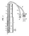
- Fig. 1 shows the essential components of the switching device of the present invention, wherein numeral 1 indicates a bundle of fibers connected to an (unshown) spectral analyzer; 2 is a sheath or cover formed around the bundled fiber 1; 3 is a holder for holding the bundled fiber 1 in position and is connected to the tip of the sheath 2 by adhesive or other fixing means 4; 5 is a tubular probe connected to the tip of the holder 3 in an axially slidable manner; 6 is an annular reflective mirror or plate fitted in the opening in the tip of the probe 5; 7 is a spring loaded between the holder 3 and probe 5 that urges the reflector 6 away from the tip of the bundled fiber 1; and 8 is a fiber incorporated in the bundled fiber 1 for transmitting and receiving light.
- numeral 1 indicates a bundle of fibers connected to an (unshown) spectral analyzer
- 2 is a sheath or cover formed around the bundled fiber 1
- 3 is a holder for holding the bundled fiber 1
- the probe 5 is capable of limited axial movement relative to the holder 3, limited by means of the engagement between annular projections 10 and 11.
- the probe 5 has a relatively small size and is made of a light material.
- the fiber 8 consists of two independent fibers 12 and. 13, one for transmitting light and the other for receiving light.
- the fiber may be a single fiber including a half mirror at a branch for transmitting and receiving light.
- the light transmitting fiber 12 is supplied with light of a given intensity from a light source 14 through a lens 15, and the light coming from the light receiving fiber 13 is converted to an electric current in a photoelectric converter 16 and compared with a reference value whereby the switch circuit 17 may be opened or closed.
- Fig 3(a) is a circuit diagram for the light source 14 and Fig. 3(b) is a circuit diagram for the photoelectric converter 16.
- the light source 14 comprises a light-emitting diode (LED) which is connected to a power through a resistor and which emits light of a given intensity which enters the light transmitting fiber 12 through the lens. The light is reflected by the annular reflector 6 and travels back through the light receiving fiber 13. Thereupon, the light is converted to an electric current by a photodiode (PD), whose output is applied to an operational amplifier 18.
- the operational amplifier 18 operates to convert an input current from the photodiode (PD) to a voltage signal and the switch circuit 17 of the spectral analyzer is actuated in response to predetermined variations in the voltage signal.
- the switching device of the present invention having the above described arrangement is used as follows.
- the holder 3 or sheath 2 is held in one hand and the probe 5 is inserted into the human body to press the outer surface of the reflector 6 against the tissue.
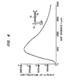
- the probe 5 is retracted against the force of the spring 7, and when the distance between the reflector 6 and the tip of the bundled fiber 8 becomes smaller than a given value, the intensity of the light sent back through a feedback loop consisting of the light source 14, the light transmitting fiber 12, the reflector 6 and the light receiving fiber 13 becomes smaller than a predetermined level, to thereby close the switch circuit 17 of the spectral analyzer.
- a measurement of the light intensity vs. gap profile is shown in Fig. 4.
- the relatively light probe 5 is supported by the spring 7 against the holder 3, so that the pressure applied to the tissue remains constant without fluctuation even if the angle at which the switching device is set on the body is varied.
- the necessary data can be obtained by simply pressing the switching device against the tissue with one hand, which not only improves the operability of the switching device but also achieves timely collection of data.
- the signals for turning on and off the switch 17 are fed optically through the optical fiber 8, making the switching device safer to use yet trouble-free.
- FIG. 5 A modification of the switching device of the present invention is shown in Fig. 5 wherein the holder 3' and probe 5' are modified as shown, and the reflector 6' is positioned on the rear end - of the probe.
- the light transmitting/receiving fiber 8 is positioned adjacent the bundled fiber 1 with its tip facing reflector 6'. This modified arrangement performs equally as well as the arrangement shown in Fig. 1.
Landscapes
- Health & Medical Sciences (AREA)
- Life Sciences & Earth Sciences (AREA)
- Physics & Mathematics (AREA)
- Pathology (AREA)
- General Health & Medical Sciences (AREA)
- Surgery (AREA)
- Public Health (AREA)
- Engineering & Computer Science (AREA)
- Biomedical Technology (AREA)
- Heart & Thoracic Surgery (AREA)
- Medical Informatics (AREA)
- Molecular Biology (AREA)
- Veterinary Medicine (AREA)
- Animal Behavior & Ethology (AREA)
- Biophysics (AREA)
- Spectroscopy & Molecular Physics (AREA)
- Optics & Photonics (AREA)
- Chemical & Material Sciences (AREA)
- Analytical Chemistry (AREA)
- Biochemistry (AREA)
- General Physics & Mathematics (AREA)
- Immunology (AREA)
- Investigating Or Analysing Materials By Optical Means (AREA)
- Measuring And Recording Apparatus For Diagnosis (AREA)
- Endoscopes (AREA)
Claims (4)
Applications Claiming Priority (2)
| Application Number | Priority Date | Filing Date | Title |
|---|---|---|---|
| JP60775/81 | 1981-04-22 | ||
| JP56060775A JPS57175345A (en) | 1981-04-22 | 1981-04-22 | Sensor for live body organ spectrum analyser |
Publications (3)
| Publication Number | Publication Date |
|---|---|
| EP0063778A2 EP0063778A2 (de) | 1982-11-03 |
| EP0063778A3 EP0063778A3 (en) | 1983-05-04 |
| EP0063778B1 true EP0063778B1 (de) | 1986-07-30 |
Family
ID=13151992
Family Applications (1)
| Application Number | Title | Priority Date | Filing Date |
|---|---|---|---|
| EP82103321A Expired EP0063778B1 (de) | 1981-04-22 | 1982-04-20 | Schaltvorrichtung für Spektralanalysator von lebendem Gewebe |
Country Status (4)
| Country | Link |
|---|---|
| US (1) | US4548505A (de) |
| EP (1) | EP0063778B1 (de) |
| JP (1) | JPS57175345A (de) |
| DE (1) | DE3272273D1 (de) |
Cited By (1)
| Publication number | Priority date | Publication date | Assignee | Title |
|---|---|---|---|---|
| DE3844651A1 (de) * | 1988-07-26 | 1990-08-30 | Kessler Manfred | Vorrichtung zum ermitteln von groessenveraenderungen an gewebepartikeln |
Families Citing this family (41)
| Publication number | Priority date | Publication date | Assignee | Title |
|---|---|---|---|---|
| CH659149A5 (de) * | 1982-03-29 | 1986-12-31 | Olten Ag Elektro Apparatebau | Schalteinrichtung mit einem schaltteil und einer in einem gehaeuse gelagerten befehls- und meldetaste. |
| GB2133137A (en) * | 1983-01-07 | 1984-07-18 | Plessey Co Plc | Fibre optic light switch |
| EP0163645A1 (de) * | 1983-02-03 | 1985-12-11 | Ljs Practice Management Limited | Optische probe zum messen der tiefe einer höhle |
| JPS59182305U (ja) * | 1983-05-20 | 1984-12-05 | 住友電気工業株式会社 | 貼付型フアイバプロ−ブ |
| US4622974A (en) * | 1984-03-07 | 1986-11-18 | University Of Tennessee Research Corporation | Apparatus and method for in-vivo measurements of chemical concentrations |
| US4743122A (en) * | 1984-12-24 | 1988-05-10 | Sanyo Electric Co., Ltd. | Infrared-ray temperature measuring apparatus |
| US4691708A (en) * | 1986-03-10 | 1987-09-08 | Cordis Corporation | Optical pressure sensor for measuring blood pressure |
| US4727730A (en) * | 1986-07-10 | 1988-03-01 | Medex, Inc. | Integrated optic system for monitoring blood pressure |
| DE3825352A1 (de) * | 1988-07-26 | 1990-02-01 | Kessler Manfred | Verfahren und vorrichtung zur bestimmung von lokalen farbstoff-konzentrationen und von streuparametern in tierischen und menschlichen geweben |
| US5284137A (en) * | 1988-07-26 | 1994-02-08 | Manfred Kessler | Process and device for the determination of local dye concentrations and of scattering parameters in animal and human tissues |
| US5080098A (en) * | 1989-12-18 | 1992-01-14 | Sentinel Monitoring, Inc. | Non-invasive sensor |
| US20010003800A1 (en) * | 1996-11-21 | 2001-06-14 | Steven J. Frank | Interventional photonic energy emitter system |
| DE69738826D1 (de) * | 1996-11-21 | 2008-08-21 | Boston Scient Ltd | |
| US6119031A (en) | 1996-11-21 | 2000-09-12 | Boston Scientific Corporation | Miniature spectrometer |
| US6185443B1 (en) | 1997-09-29 | 2001-02-06 | Boston Scientific Corporation | Visible display for an interventional device |
| US6238348B1 (en) | 1997-07-22 | 2001-05-29 | Scimed Life Systems, Inc. | Miniature spectrometer system and method |
| US6324418B1 (en) | 1997-09-29 | 2001-11-27 | Boston Scientific Corporation | Portable tissue spectroscopy apparatus and method |
| US5984861A (en) * | 1997-09-29 | 1999-11-16 | Boston Scientific Corporation | Endofluorescence imaging module for an endoscope |
| US6096065A (en) | 1997-09-29 | 2000-08-01 | Boston Scientific Corporation | Sheath for tissue spectroscopy |
| US5902247A (en) * | 1997-09-09 | 1999-05-11 | Bioenterics Corporation | Transilluminating catheter |
| US6289229B1 (en) | 1998-01-20 | 2001-09-11 | Scimed Life Systems, Inc. | Readable probe array for in vivo use |
| US6444970B1 (en) | 1998-06-26 | 2002-09-03 | Scimed Life Systems, Inc. | Miniature low-noise photodiode system |
| WO2003076883A2 (en) * | 2002-03-08 | 2003-09-18 | Sensys Medical, Inc. | Compact apparatus for noninvasive measurement of glucose through near-infrared spectroscopy |
| US7606608B2 (en) | 2000-05-02 | 2009-10-20 | Sensys Medical, Inc. | Optical sampling interface system for in-vivo measurement of tissue |
| US7519406B2 (en) * | 2004-04-28 | 2009-04-14 | Sensys Medical, Inc. | Noninvasive analyzer sample probe interface method and apparatus |
| US6534012B1 (en) * | 2000-08-02 | 2003-03-18 | Sensys Medical, Inc. | Apparatus and method for reproducibly modifying localized absorption and scattering coefficients at a tissue measurement site during optical sampling |
| US20060211931A1 (en) * | 2000-05-02 | 2006-09-21 | Blank Thomas B | Noninvasive analyzer sample probe interface method and apparatus |
| US7697966B2 (en) * | 2002-03-08 | 2010-04-13 | Sensys Medical, Inc. | Noninvasive targeting system method and apparatus |
| US20050054908A1 (en) * | 2003-03-07 | 2005-03-10 | Blank Thomas B. | Photostimulation method and apparatus in combination with glucose determination |
| US8504128B2 (en) * | 2002-03-08 | 2013-08-06 | Glt Acquisition Corp. | Method and apparatus for coupling a channeled sample probe to tissue |
| US20070149868A1 (en) * | 2002-03-08 | 2007-06-28 | Blank Thomas B | Method and Apparatus for Photostimulation Enhanced Analyte Property Estimation |
| US8718738B2 (en) | 2002-03-08 | 2014-05-06 | Glt Acquisition Corp. | Method and apparatus for coupling a sample probe with a sample site |
| US8328877B2 (en) | 2002-03-19 | 2012-12-11 | Boston Scientific Scimed, Inc. | Stent retention element and related methods |
| US20040082842A1 (en) * | 2002-10-28 | 2004-04-29 | Lumba Vijay K. | System for monitoring fetal status |
| US20070234300A1 (en) * | 2003-09-18 | 2007-10-04 | Leake David W | Method and Apparatus for Performing State-Table Driven Regression Testing |
| US8868147B2 (en) * | 2004-04-28 | 2014-10-21 | Glt Acquisition Corp. | Method and apparatus for controlling positioning of a noninvasive analyzer sample probe |
| US20080033275A1 (en) * | 2004-04-28 | 2008-02-07 | Blank Thomas B | Method and Apparatus for Sample Probe Movement Control |
| US20060206018A1 (en) * | 2005-03-04 | 2006-09-14 | Alan Abul-Haj | Method and apparatus for noninvasive targeting |
| US20090036759A1 (en) * | 2007-08-01 | 2009-02-05 | Ault Timothy E | Collapsible noninvasive analyzer method and apparatus |
| US8280471B2 (en) * | 2007-12-12 | 2012-10-02 | Kimberly-Clark Worldwide, Inc. | Fiber optic based detection of autofluorescent bacterial pathogens |
| US20090155770A1 (en) * | 2007-12-12 | 2009-06-18 | Kimberly-Clark Worldwide, Inc. | Implantable devices for fiber optic based detection of nosocomial infection |
Family Cites Families (8)
| Publication number | Priority date | Publication date | Assignee | Title |
|---|---|---|---|---|
| US3327712A (en) * | 1961-09-15 | 1967-06-27 | Ira H Kaufman | Photocoagulation type fiber optical surgical device |
| FR2102628A5 (de) * | 1970-08-12 | 1972-04-07 | Compteurs Comp D | |
| JPS6043134B2 (ja) * | 1977-08-25 | 1985-09-26 | 信紘 佐藤 | 生体の臓器,組識の反射特性測定装置 |
| US4269192A (en) * | 1977-12-02 | 1981-05-26 | Olympus Optical Co., Ltd. | Stabbing apparatus for diagnosis of living body |
| FR2410809A1 (fr) * | 1977-12-05 | 1979-06-29 | Jacques Beaufront | Procede et dispositif opto-electronique pour la mesure de grandeurs physiques |
| US4281931A (en) * | 1977-12-21 | 1981-08-04 | Machida Endoscope Co., Ltd. | Measuring apparatus comprising light optics utilizing cylindrical focusing glass fiber |
| US4210029A (en) * | 1979-05-04 | 1980-07-01 | Lad Research Industries, Inc. | Differential fiber optic differential pressure sensor |
| JPS5720261A (en) * | 1980-07-14 | 1982-02-02 | Olympus Optical Co | Medical treating device |
-
1981
- 1981-04-22 JP JP56060775A patent/JPS57175345A/ja active Pending
-
1982
- 1982-04-19 US US06/369,767 patent/US4548505A/en not_active Expired - Fee Related
- 1982-04-20 EP EP82103321A patent/EP0063778B1/de not_active Expired
- 1982-04-20 DE DE8282103321T patent/DE3272273D1/de not_active Expired
Cited By (1)
| Publication number | Priority date | Publication date | Assignee | Title |
|---|---|---|---|---|
| DE3844651A1 (de) * | 1988-07-26 | 1990-08-30 | Kessler Manfred | Vorrichtung zum ermitteln von groessenveraenderungen an gewebepartikeln |
Also Published As
| Publication number | Publication date |
|---|---|
| DE3272273D1 (en) | 1986-09-04 |
| JPS57175345A (en) | 1982-10-28 |
| EP0063778A3 (en) | 1983-05-04 |
| EP0063778A2 (de) | 1982-11-03 |
| US4548505A (en) | 1985-10-22 |
Similar Documents
| Publication | Publication Date | Title |
|---|---|---|
| EP0063778B1 (de) | Schaltvorrichtung für Spektralanalysator von lebendem Gewebe | |
| EP0043133B1 (de) | Lichtquelle für ein optisches Gerät | |
| US5891016A (en) | Fluorescence endoscope having an exciting light filter and a fluorescence filter | |
| JPS641004B2 (de) | ||
| US6270491B1 (en) | Intensity controllable hand-held surgical light | |
| US6590648B1 (en) | Apparatus for measuring light | |
| US5993442A (en) | Medical laser irradiation apparatus | |
| GB9717858D0 (en) | The Electrode Company Ltd | |
| EP1772096B1 (de) | Sicherheits- und Steuerungssystem für die Lichtquelle eines Endoskops mit einem optischen Sensor | |
| JPS57123497A (en) | Measuring apparatus utilizing optical fiber | |
| TW349873B (en) | Optical fiber unit for medical examination and treatment and arm device for the optical fiber | |
| CA2461599A1 (fr) | Dispositif de mesure des caracteristiques d'absorption lumineuse d'un echantillon de tissu biologique | |
| JP3547968B2 (ja) | 脈拍波形検出装置 | |
| EP0675352A3 (de) | Reflexionssonde mit optischen Fasern | |
| US4945366A (en) | Endoscope still photographing apparatus provided with an automatic illuminating light amount controlling function | |
| SE8401912D0 (sv) | Forfarande och anordning for metning av effekten hos infallande ljus | |
| JPS6314616B2 (de) | ||
| JP2001321338A (ja) | 内視鏡用光源装置 | |
| JP2745870B2 (ja) | 皮膚分析装置 | |
| CA2361352A1 (en) | Analytical quantification and process control | |
| JPH02236127A (ja) | 色の測定方法及び色の測定装置 | |
| JP2595981B2 (ja) | 光学濃度測定器 | |
| JPH023460B2 (de) | ||
| JPS6468711A (en) | Endoscope device | |
| JP2526451B2 (ja) | 皮膚分析装置 |
Legal Events
| Date | Code | Title | Description |
|---|---|---|---|
| PUAI | Public reference made under article 153(3) epc to a published international application that has entered the european phase |
Free format text: ORIGINAL CODE: 0009012 |
|
| AK | Designated contracting states |
Designated state(s): CH DE FR GB LI NL SE |
|
| 17P | Request for examination filed |
Effective date: 19821027 |
|
| PUAL | Search report despatched |
Free format text: ORIGINAL CODE: 0009013 |
|
| AK | Designated contracting states |
Designated state(s): CH DE FR GB LI NL SE |
|
| GRAA | (expected) grant |
Free format text: ORIGINAL CODE: 0009210 |
|
| AK | Designated contracting states |
Kind code of ref document: B1 Designated state(s): CH DE FR GB LI NL SE |
|
| ET | Fr: translation filed | ||
| REF | Corresponds to: |
Ref document number: 3272273 Country of ref document: DE Date of ref document: 19860904 |
|
| PLBE | No opposition filed within time limit |
Free format text: ORIGINAL CODE: 0009261 |
|
| STAA | Information on the status of an ep patent application or granted ep patent |
Free format text: STATUS: NO OPPOSITION FILED WITHIN TIME LIMIT |
|
| 26N | No opposition filed | ||
| EAL | Se: european patent in force in sweden |
Ref document number: 82103321.4 |
|
| PGFP | Annual fee paid to national office [announced via postgrant information from national office to epo] |
Ref country code: GB Payment date: 19950410 Year of fee payment: 14 |
|
| PGFP | Annual fee paid to national office [announced via postgrant information from national office to epo] |
Ref country code: FR Payment date: 19950411 Year of fee payment: 14 |
|
| PGFP | Annual fee paid to national office [announced via postgrant information from national office to epo] |
Ref country code: CH Payment date: 19950413 Year of fee payment: 14 |
|
| PGFP | Annual fee paid to national office [announced via postgrant information from national office to epo] |
Ref country code: SE Payment date: 19950419 Year of fee payment: 14 |
|
| PGFP | Annual fee paid to national office [announced via postgrant information from national office to epo] |
Ref country code: DE Payment date: 19950421 Year of fee payment: 14 |
|
| PGFP | Annual fee paid to national office [announced via postgrant information from national office to epo] |
Ref country code: NL Payment date: 19950430 Year of fee payment: 14 |
|
| PG25 | Lapsed in a contracting state [announced via postgrant information from national office to epo] |
Ref country code: GB Effective date: 19960420 |
|
| PG25 | Lapsed in a contracting state [announced via postgrant information from national office to epo] |
Ref country code: SE Effective date: 19960421 |
|
| PG25 | Lapsed in a contracting state [announced via postgrant information from national office to epo] |
Ref country code: LI Effective date: 19960430 Ref country code: CH Effective date: 19960430 |
|
| PG25 | Lapsed in a contracting state [announced via postgrant information from national office to epo] |
Ref country code: NL Effective date: 19961101 |
|
| GBPC | Gb: european patent ceased through non-payment of renewal fee |
Effective date: 19960420 |
|
| REG | Reference to a national code |
Ref country code: CH Ref legal event code: PL |
|
| PG25 | Lapsed in a contracting state [announced via postgrant information from national office to epo] |
Ref country code: FR Effective date: 19961227 |
|
| PG25 | Lapsed in a contracting state [announced via postgrant information from national office to epo] |
Ref country code: DE Effective date: 19970101 |
|
| NLV4 | Nl: lapsed or anulled due to non-payment of the annual fee |
Effective date: 19961101 |
|
| EUG | Se: european patent has lapsed |
Ref document number: 82103321.4 |
|
| REG | Reference to a national code |
Ref country code: FR Ref legal event code: ST |