EP0064304A1 - Hebevorrichtung für Lastkraftwagen - Google Patents
Hebevorrichtung für Lastkraftwagen Download PDFInfo
- Publication number
- EP0064304A1 EP0064304A1 EP82200089A EP82200089A EP0064304A1 EP 0064304 A1 EP0064304 A1 EP 0064304A1 EP 82200089 A EP82200089 A EP 82200089A EP 82200089 A EP82200089 A EP 82200089A EP 0064304 A1 EP0064304 A1 EP 0064304A1
- Authority
- EP
- European Patent Office
- Prior art keywords
- platform
- truck
- cylinders
- lifting device
- loading platform
- Prior art date
- Legal status (The legal status is an assumption and is not a legal conclusion. Google has not performed a legal analysis and makes no representation as to the accuracy of the status listed.)
- Withdrawn
Links
- 239000007788 liquid Substances 0.000 claims description 2
- 238000006073 displacement reaction Methods 0.000 claims 1
- 229920002994 synthetic fiber Polymers 0.000 claims 1
- 239000012530 fluid Substances 0.000 abstract 1
- 210000001331 nose Anatomy 0.000 description 10
- 238000005086 pumping Methods 0.000 description 2
- 230000005540 biological transmission Effects 0.000 description 1
- 238000010276 construction Methods 0.000 description 1
- 210000000887 face Anatomy 0.000 description 1
- 210000003128 head Anatomy 0.000 description 1
Images

Classifications
-
- B—PERFORMING OPERATIONS; TRANSPORTING
- B60—VEHICLES IN GENERAL
- B60P—VEHICLES ADAPTED FOR LOAD TRANSPORTATION OR TO TRANSPORT, TO CARRY, OR TO COMPRISE SPECIAL LOADS OR OBJECTS
- B60P1/00—Vehicles predominantly for transporting loads and modified to facilitate loading, consolidating the load, or unloading
- B60P1/44—Vehicles predominantly for transporting loads and modified to facilitate loading, consolidating the load, or unloading having a loading platform thereon raising the load to the level of the load-transporting element
- B60P1/4414—Vehicles predominantly for transporting loads and modified to facilitate loading, consolidating the load, or unloading having a loading platform thereon raising the load to the level of the load-transporting element and keeping the loading platform parallel to the ground when raising the load
- B60P1/4421—Vehicles predominantly for transporting loads and modified to facilitate loading, consolidating the load, or unloading having a loading platform thereon raising the load to the level of the load-transporting element and keeping the loading platform parallel to the ground when raising the load the loading platform being carried in at least one vertical guide
Definitions
- the invention relates to a lifting device for trucks, namely a lifting device which, between the ground and the loading floor of a truck or higher, is movable in height and which, in "vertical position siding, can close the open end of the truck.
- lifting devices consisting in main order of a loading platform, placed right against the open rear end of the truck, of means comprising chains or cables, for moving the platform in height. loading between the ground and the loading floor of a truck or for moving it higher, and guide means for guiding the loading platform during the movement thereof.
- the means used here for moving the loading platform in height have the disadvantage of being relatively complicated and of a costly construction. They can also be easily disturbed in service.
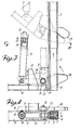
- the means for moving the loading platform in height consist of two hydraulic cylinders of a preferably long stroke length, which cylinders are pivotally fixed between each lateral side of the loading platform and the fixed part of the truck, while between the cylinders and a hydraulic pump used for supplying the aforementioned cylinders, a flow regulator is provided for distributing the liquid uniformly over the two cylinders so that the movement of the latter is uniform.
- the loading platform is therefore directly attacked by the hydraulic cylinders, without the intervention of transmission members. The loss of power is thus limited, less effort is required and the efficiency is higher.
- each guide section 1 a slat 4 is placed on which a plastic furring strip 2 is fixed, this by means of bolts 5 whose head and nut are placed so as to be embedded in the recesses 6 of said fur. This fur can move in height with the slat in the guide profile 1.
- a longitudinal slot 3 is provided, through which the slat which extends outside the profile.
- a lug 7 is welded through which an axis 80 is passed.
- each hydraulic cylinder 11 there is housed a piston 14 with piston rod 15 in which an axial channel 16 is provided which, via one or more lateral openings 17 provided in the wall of the piston rod 15, opens into the interior space of the hydraulic cylinder 11, which interior space is located above the piston.
- each piston rod 15 is pivotally attached by a pin 18 to the corresponding guide profile 1.
- Each axial channel 16 is connected to a hydraulic pump 26 mounted on the truck, by means of a flexible pipe 19 via a flow regulator 25 which serves to distribute the oil in a uniform manner over the two cylinares. Thanks to this arrangement, the two cylinders operate in exactly the same way, so that the two lateral sides of the loading platform move in height while remaining perfectly parallel. Faults are easily avoided.
- a pivotable nose 20 which, in the position shown in FIG. 3, is held by the plane 21 of the nose which rests against the stop 22, provided on the loading platform 12.
- This pivotable nose 20 can operate with a fixed stop 23 which is fixed on the guide profile 1, this being designed to bring the loading platform to the vertical position.
- the fixed noses 13 provided on the two lateral faces of the loading platform 12 each operate with an end stop 24, provided on each guide profile 1 and serve to limit the position vertical, the stroke of the loading platform.
- the hydraulic pump 25, mounted on the truck is put into service in such a way that the oil is extracted from the hydraulic cylinders 11 by pumping via the flow regulator 25, the axial channel 16 and the opening 17 of each piston rod 15.
- the flow regulator 25 then ensures that the cylinders 11 are uniformly emptied by pumping.
- the weight of the loading platform 12, that of the parts mounted on this platform and that of the hydraulic cylinders 11, allow these cylinders to descend by sliding on the pistons 14 so that the loading platform 12 descends on the ground while the slats 4 with the furs 2 which move in height in the guide profiles 1, guide the loading platform.
- the swivel nose 20 is rotated about 180 ° around the axis 8, as it is seen in point-bar line in fig. 3, then the hydraulic pump 26 and the flow regulator 25, mounted on the truck, are put into service.
- the oil under pressure is pumped into the interior space of the hydraulic cylinders 11 via the flexible pipes 19, the axial channel 16 and the opening 17 of each piston rod 15, in such a way that the cylinders 11 are pressed uniformly upwards on the pistons 14.
- these cylinders pull up the loading platform 12 which rises remaining perfectly horizontal, while the slats 4 with the furring strips 2 are guided in the guide profiles 1.
- the hydraulic pump 23 and the flow regulator 25 are switched off so that the whole mechanism stops. If desired, the loading platform can also be moved higher.
- each hydraulic cylinder 11 can also be coupled to the lug 7 in a pivoting manner, instead of being coupled to the supports _'axis 9
Landscapes
- Engineering & Computer Science (AREA)
- Transportation (AREA)
- Mechanical Engineering (AREA)
- Loading Or Unloading Of Vehicles (AREA)
Applications Claiming Priority (2)
| Application Number | Priority Date | Filing Date | Title |
|---|---|---|---|
| BE2059117 | 1981-04-15 | ||
| BE2/59117A BE888428A (nl) | 1981-04-15 | 1981-04-15 | Hefinrichting voor vrachtwagens, |
Publications (1)
| Publication Number | Publication Date |
|---|---|
| EP0064304A1 true EP0064304A1 (de) | 1982-11-10 |
Family
ID=3865547
Family Applications (1)
| Application Number | Title | Priority Date | Filing Date |
|---|---|---|---|
| EP82200089A Withdrawn EP0064304A1 (de) | 1981-04-15 | 1982-01-26 | Hebevorrichtung für Lastkraftwagen |
Country Status (1)
| Country | Link |
|---|---|
| EP (1) | EP0064304A1 (de) |
Cited By (7)
| Publication number | Priority date | Publication date | Assignee | Title |
|---|---|---|---|---|
| GB2160175A (en) * | 1984-06-15 | 1985-12-18 | Chown Peter A C | Wheelchair lift |
| US4930971A (en) * | 1987-02-21 | 1990-06-05 | Wilson Frederick G | Lift platform for road vehicles and trailers |
| US4948326A (en) * | 1987-05-22 | 1990-08-14 | Henry Bedard | Load lifting attachment mounted on a truck frame |
| US5171123A (en) * | 1991-04-08 | 1992-12-15 | Nuyts Karolus M L | Load lifting device on a truck |
| US5433580A (en) * | 1991-05-15 | 1995-07-18 | Hogan Mfg., Inc. | Wheelchair lift with hinged connection joint |
| EP0699557A1 (de) * | 1994-09-02 | 1996-03-06 | Nuyts Orb | An einem Fahrzeug anbringbare Lastenaufzugseinrichtung |
| BE1010003A3 (nl) * | 1995-10-20 | 1997-11-04 | Dhollandia Naamloze Vennootsch | Scharnierbare laadklep. |
Citations (8)
| Publication number | Priority date | Publication date | Assignee | Title |
|---|---|---|---|---|
| US2418494A (en) * | 1945-02-16 | 1947-04-08 | Anthony Co | Twin lift |
| LU52002A1 (de) * | 1965-09-20 | 1966-11-21 | ||
| BE736114A (de) * | 1969-07-15 | 1969-12-16 | ||
| US3918596A (en) * | 1974-05-14 | 1975-11-11 | Ward School Bus Mfg Inc | School bus invalid lift |
| GB1421552A (en) * | 1972-12-27 | 1976-01-21 | Gemert A J Van | Loading and unloading flap device particularly for a truck |
| US4138023A (en) * | 1976-10-18 | 1979-02-06 | Collins Industries, Inc. | Vehicle wheelchair lift |
| BE876399A (nl) * | 1979-05-21 | 1979-09-17 | Solid P V B A | Hydraulische cilinder gemonteerd op een lift |
| GB2024767A (en) * | 1978-05-31 | 1980-01-16 | Ratcliff Tail Lifts Ltd | Improvements in or relating to load lifting and lowering apparatus |
-
1982
- 1982-01-26 EP EP82200089A patent/EP0064304A1/de not_active Withdrawn
Patent Citations (8)
| Publication number | Priority date | Publication date | Assignee | Title |
|---|---|---|---|---|
| US2418494A (en) * | 1945-02-16 | 1947-04-08 | Anthony Co | Twin lift |
| LU52002A1 (de) * | 1965-09-20 | 1966-11-21 | ||
| BE736114A (de) * | 1969-07-15 | 1969-12-16 | ||
| GB1421552A (en) * | 1972-12-27 | 1976-01-21 | Gemert A J Van | Loading and unloading flap device particularly for a truck |
| US3918596A (en) * | 1974-05-14 | 1975-11-11 | Ward School Bus Mfg Inc | School bus invalid lift |
| US4138023A (en) * | 1976-10-18 | 1979-02-06 | Collins Industries, Inc. | Vehicle wheelchair lift |
| GB2024767A (en) * | 1978-05-31 | 1980-01-16 | Ratcliff Tail Lifts Ltd | Improvements in or relating to load lifting and lowering apparatus |
| BE876399A (nl) * | 1979-05-21 | 1979-09-17 | Solid P V B A | Hydraulische cilinder gemonteerd op een lift |
Cited By (7)
| Publication number | Priority date | Publication date | Assignee | Title |
|---|---|---|---|---|
| GB2160175A (en) * | 1984-06-15 | 1985-12-18 | Chown Peter A C | Wheelchair lift |
| US4930971A (en) * | 1987-02-21 | 1990-06-05 | Wilson Frederick G | Lift platform for road vehicles and trailers |
| US4948326A (en) * | 1987-05-22 | 1990-08-14 | Henry Bedard | Load lifting attachment mounted on a truck frame |
| US5171123A (en) * | 1991-04-08 | 1992-12-15 | Nuyts Karolus M L | Load lifting device on a truck |
| US5433580A (en) * | 1991-05-15 | 1995-07-18 | Hogan Mfg., Inc. | Wheelchair lift with hinged connection joint |
| EP0699557A1 (de) * | 1994-09-02 | 1996-03-06 | Nuyts Orb | An einem Fahrzeug anbringbare Lastenaufzugseinrichtung |
| BE1010003A3 (nl) * | 1995-10-20 | 1997-11-04 | Dhollandia Naamloze Vennootsch | Scharnierbare laadklep. |
Similar Documents
| Publication | Publication Date | Title |
|---|---|---|
| CA2120715A1 (fr) | Tourelle pour vehicule de transport de materiaux et convoyeur telescopique monte sur une telle tourelle | |
| FR2486052A1 (fr) | Fleche telescopique a troncons guides mutuellement | |
| CA1305960C (fr) | Agitateur notamment pour four a micro-ondes | |
| EP0029384A1 (de) | Gabelstapler mit gleichzeitiger Steuerung von verstellbar angetriebenen Roll- und Greifflächen | |
| EP0064304A1 (de) | Hebevorrichtung für Lastkraftwagen | |
| CA2530540A1 (fr) | Elevateur | |
| CH633054A5 (fr) | Machine de chantier ferroviaire equipee d'une unite mecanique de deplacement de la voie ferree. | |
| FR2821833A1 (fr) | Convoyeur a bande | |
| EP2001710B1 (de) | Hubfahrzeug für in grossen höhen arbeitende personen | |
| EP0843046B1 (de) | Vorrichtung zum Kehren und Aufnehmen von Material | |
| FR2487625A1 (fr) | Dispositif de porte-electrode pour four de fusion electrothermique | |
| FR2514819A1 (fr) | Dispositif de commande de niveau pour engin d'abattage | |
| FR2536784A1 (fr) | Dispositif de commande verticale d'un rabot pour la commande du niveau d'un rabot a charbon | |
| FR2825990A1 (fr) | Dispositif de nettoyage mecanique de silos de stockage | |
| EP0433517A1 (de) | Kompakter Müllsammelbehälter mit Verdichtungsvorrichtung | |
| EP0014153A1 (de) | Vorrichtung zum Aufnehmen, Transportieren und Verteilen von Materialien | |
| FR3076287B1 (fr) | Dispositif de deversement lateral de matiere, notamment d'enrobes, et systeme le comprenant | |
| FR2649388A1 (fr) | Chariots elevateurs industriels et guides de tube pour ces chariots | |
| FR2514289A1 (fr) | Dispositif de levage et de basculement de chargeur de betonniere ou de malaxeur | |
| FR2598647A1 (fr) | Dispositif permettant de separer des parts d'une matiere molle, pateuse ou granuleuse | |
| EP0119366A1 (de) | Toilettenvorrichtung mit einer hydraulischen Klappe eingebaut im Endteil eines Siphons | |
| FR2676678A1 (fr) | Dispositif de support et de reglage en hauteur du tiroir d'une machine de moulage de produits en beton. | |
| FR2634345A1 (fr) | Dispositif de commande du volet deflecteur et de la goulotte distributrice d'une machine a distribuer des fourrages | |
| FR2640184A1 (fr) | Dispositif pour la fabrication, par moulage et compression d'un materiau, d'elements de construction prefabriques, tels que parpaings, hourdis, conduits de cheminees, paves ou dalles | |
| FR2664882A1 (fr) | Dispositif pour le compactage de dechets dans un conteneur mobile. |
Legal Events
| Date | Code | Title | Description |
|---|---|---|---|
| PUAI | Public reference made under article 153(3) epc to a published international application that has entered the european phase |
Free format text: ORIGINAL CODE: 0009012 |
|
| AK | Designated contracting states |
Designated state(s): DE FR GB LU NL |
|
| STAA | Information on the status of an ep patent application or granted ep patent |
Free format text: STATUS: THE APPLICATION IS DEEMED TO BE WITHDRAWN |
|
| 18D | Application deemed to be withdrawn |
Effective date: 19831017 |