EP0064584A1 - Procédé et dispositif pour déposer un ruban de fibres textiles - Google Patents
Procédé et dispositif pour déposer un ruban de fibres textiles Download PDFInfo
- Publication number
- EP0064584A1 EP0064584A1 EP82102143A EP82102143A EP0064584A1 EP 0064584 A1 EP0064584 A1 EP 0064584A1 EP 82102143 A EP82102143 A EP 82102143A EP 82102143 A EP82102143 A EP 82102143A EP 0064584 A1 EP0064584 A1 EP 0064584A1
- Authority
- EP
- European Patent Office
- Prior art keywords
- rotation
- axes
- distance
- wheel
- belt
- Prior art date
- Legal status (The legal status is an assumption and is not a legal conclusion. Google has not performed a legal analysis and makes no representation as to the accuracy of the status listed.)
- Granted
Links
Images

Classifications
-
- B—PERFORMING OPERATIONS; TRANSPORTING
- B65—CONVEYING; PACKING; STORING; HANDLING THIN OR FILAMENTARY MATERIAL
- B65H—HANDLING THIN OR FILAMENTARY MATERIAL, e.g. SHEETS, WEBS, CABLES
- B65H54/00—Winding, coiling, or depositing filamentary material
- B65H54/76—Depositing materials in cans or receptacles
- B65H54/80—Apparatus in which the depositing device or the receptacle is rotated
-
- B—PERFORMING OPERATIONS; TRANSPORTING
- B65—CONVEYING; PACKING; STORING; HANDLING THIN OR FILAMENTARY MATERIAL
- B65H—HANDLING THIN OR FILAMENTARY MATERIAL, e.g. SHEETS, WEBS, CABLES
- B65H2701/00—Handled material; Storage means
- B65H2701/30—Handled filamentary material
- B65H2701/31—Textiles threads or artificial strands of filaments
Definitions
- the present invention relates to a method for depositing a textile sliver in the form of cycloid-like loops in a can which rotates about its longitudinal axis forming the axis of rotation, in which the sliver is guided through a funnel of a funnel wheel which is parallel to the can rotation axis
- the axis of rotation rotates, and in addition the mutual distance between the axes of rotation of the can and the funnel wheel is changed by a lateral displacement of the can in the direction perpendicular to the axes.
- German Offenlegungsschrift No. 28 02 216 describes a method which is used to deposit and transfer fuses into a jug by means of a funnel wheel.
- the funnel wheel is also used for large turns and, in the case of small turns, also the can using a transmission gear with a periodically changing angular velocity turns. These changes in angular velocity occur in time with the rotation of the funnel wheel and thus at a very high frequency. Great forces arise.
- the course or configuration of the belt loops placed in the jug is not influenced by the measures mentioned.
- the can for depositing roving into a can to increase its capacity, the can is subjected to a translational movement in addition to its rotational movement, with the funnel wheel being firmly positioned.
- the degree of filling is insufficient in the first-mentioned process and that in the second-mentioned process the band gap between the individual loops of the sliver deposited in the can fluctuates depending on the can diameter.
- the sliver warps and, above all, there are non-uniform parts in terms of its thickness, which non-uniformities can have an effect right up to the finally manufactured product.
- the rotational speed of the can varies as a function of the distance between the axes of rotation of the can and the funnel wheel, and the can is rotated at the maximum rotational speed with a minimum distance between these axes and the can with the minimum rotational speed at the maximum distance between these axes.
- the device for carrying out the method has a rotatable can plate carrying the can, which is coupled to a rotating member. It is characterized in that a drive element of constant rotation speed is provided on the input side of a translation variator which is controllable as a function of the distance between the rotation axes of the can and funnel, and the rotation element is provided on the output side.
- the present invention results in a further advantage, as a rule, of an even further improved degree of filling of the can filled with fiber sliver.
- the appearance of the filled jug is also improved.
- the device for depositing a sliver shown in FIGS. 1 and 2 has two cans 11 each for receiving a sliver.
- Fig. 2 only the lower part of a can 11 is drawn.
- the cans 11 stand on can plates 12 (FIG. 2), which are mounted in rotary bearings (not shown). They are rotatable about axes of rotation 13.
- the rotary bearing of the can plate and thus the cans 11 are carried by a plate 14 and this in turn is mounted on rollers 15.
- the latter run on rails 16 so that the plate 14 can perform translatory movements.
- a drive member 21 formed by a drive shaft can be rotated at a constant rotational speed. It is firmly coupled to a V-belt wheel 51 and is rotatably carried by a hatched, fixed part of the device. Via a V-belt 22 it is coupled to a rotating member 23 designed as a V-belt pulley. The latter is coupled via further belts 24 to the can plates 12 carrying the cans 11. Via a gear wheel 52, which rotates with the rotating member 23, the rotating member 23 is also coupled to a rotatable disk 25, which is provided with a toothed ring over its circumference. On the disk 25, one end of a crank rod 26 can be rotated in a rotary bearing 27 mounted eccentrically on the disk 25 consolidates. The other end of the crank rod 26 is pivotally attached to a solid part of the device shown hatched. When the disk 25 rotates, the rotary bearing 27 for the crank rod 26 describes the path shown by the circle 28.
- funnel wheel 31 each.
- these funnel wheels 31 rotate about one of the axes of rotation 32.
- the fiber slivers to be deposited into the cans 11 run through their funnels 33.
- the distance from an axis of rotation 32 to the associated funnel 33 forms the placement radius of the funnel wheel.
- each of the hopper wheels 31 rotates continuously about its axis of rotation 32.
- the drive member 21 rotates at a constant speed and sets the V-belt wheels 51 and 23 in rotation.
- the organ 23 in turn causes the belts 24 to rotate the can plates 12 and the cans 11 mounted thereon.
- the disk 25, in the toothed ring of which the teeth of the gear wheel 52 engage is rotated by the drive element 21 and via the rotating element 23 , whereby the plate 14 is moved back and forth on the rollers 15 along the rails 16.
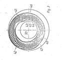
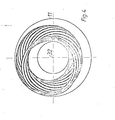
- the funnel wheel 31 Due to the simultaneous rotation of the funnel wheels 31 and the cans 11, the funnel wheel 31 making, for example, 20 rotations with each revolution of a can 11, the fiber sliver is deposited in the cans in cycloid-like, adjacent loops. The area around the rotation remains Axes 13 freely in each of the cans 11, so that this area forms a hole when the can 11 is filled. As is generally known in the spinning industry, the sliver can be deposited "around the hole” or "to the hole”. When placing "around the hole”, the funnel 33 of the funnel wheel 31 rotates about the axis 13 of the can 11. When placing "around the hole”, it rotates on a path lying between the axis 13 and the cylindrical wall of the can 11. Figures 1,3 and 4 show trays "around the hole”.
- FIGS. 3 and 4 show loops of a sliver inserted into a can 11.
- the loops are drawn as lines.
- the bands are therefore actually wider and closer together than is shown in FIGS. 3 and 4.
- a 600 mm diameter jug and a hopper wheel with a disc radius of 218 mm were used.
- Fig. 3 shows a tape storage, which is created by a combination of the rotation and translation of the can 11 described in the previous paragraph. A good filling is already achieved. However, the loops are still relatively close together in area 41 and have relatively large distances from one another in area 42.
- the rotational speed of the cans 11 is varied according to the invention in such a way that each can 11 has the greatest rotational speed if, during the lateral displacement of the can 11, its axis of rotation 13 is the axis of rotation 32 of the one belonging to it Funnel wheel 31 is closest, ie if it is placed in the innermost area of the jug. Accordingly, the speed of rotation of the can 11 is slowest when the axes of rotation 13 and 32 are at their greatest distance during the lateral displacement of the can 11, i.e. if it is placed on the edge of the can.
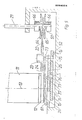
- FIG. 1 shows a device with which such a variation in the rotational speed of the cans 11 by means of the from the An drive member 21, the rotating member 23 and the V-belt 22 existing V-belt variator is obtained.
- the V-belt wheel 51 driven by the drive element 21 has two wheel halves which are preloaded against one another in the axial direction and whose mutual distance can be changed, as will be explained in more detail later with reference to the example in FIG. 5. If, for example, the plate 14 is moved along the rails 16 by the rotation of the disk 25, the cans 11 being moved from their positions into the positions defined by the corresponding circles 17, this results in an increase in the distance between the fixed V-belt pulley 51 from the rotating member 23 moved with the plate 14.
- FIG. 5 is an embodiment of a drive arrangement for moving a can plate shown in detail.
- a can 11 placed on a can plate 12.
- the plate 12 is supported by a plate 14 in a rotary bearing, not shown.
- the plate 14 is movable back and forth on rollers 15.
- a crank rod 26, which is pivotally attached at one end 61 to a hatched, fixed machine part, is rotatably coupled to a disk 25 at its other end by means of a rotary bearing 27.
- the bearing 27 is arranged eccentrically with respect to the axis of rotation 76 of the disk 25.
- the drive arrangement comprises a drive element 21 designed as a shaft. It also has a transmission variator which comprises a V-belt wheel 51, a rotation element 23 designed as a V-belt pulley and a V-belt 22 coupling these wheels 51, 23.
- the V-belt wheel 51 is composed of two wheel halves 64 and 65, which are biased against one another by means of two springs 66.
- the wheel halves 64, 65 are displaceable in the longitudinal direction of the drive shaft 21 and are driven by the latter.
- the can plate 12 is driven by a wheel 73 which is rotationally coupled to the rotating member 23.
- a gear 52 is also coupled to the organ 23 in terms of rotation.
- the wheels 23, 73 and 52 are supported by a rotary bearing 75.
- the gear 52 is in engagement with a ring gear arranged over the circumference of the disk 25.
- the disk 25 can be rotated about the axis of rotation 76 in a bearing 77.
- the V-belt variator 51, 23, 22 shown in FIG. 5 operates essentially in the manner described with reference to FIGS. 1 and 2 and serves to explain it in detail:
- the drive member 21 sets the rotary member 23 in motion via the V-belt wheel 51 and the V-belt 22 .
- This causes the can plate 12 and the disk 25 to rotate via the belt 24 or the interlocking teeth of the gear 52 and the ring gear of the disk 25.
- the rotating disk 25, via the rotating bearing 27 and the crank rod 26, causes a back and forth movement of the plate 14 and thus of the can plate 12 carried by it, together with the can 11 and the wheel group 23, 73, 52. If e.g. 5 moves to the right in FIG. 5, the rotating member 23 also moves to the right.
- the rotating member 23 can be designed as a V-belt pulley with two mutually preloaded pulley halves of variable spacing.
- Each of the mutually facing inner surfaces of the wheel halves 64, 65 has the shape of the outer surface of a truncated cone-like structure. If the generatrices of these lateral surfaces are formed by straight lines, the transmission ratio of the wheels 51, 23 changes in proportion to their distance from one another or to the radial spacing of the V-belt 22. If one selects a line with a predetermined, curved course for the generators, one obtains an arbitrarily selectable change in the gear ratio as a function of the mutual distance between the wheel halves 64, 65.
- the lateral displacement of the plate 14 along the rails 16 is influenced by the changed rotational speed of the rotating member 23. If, for example, the disk 25 were driven directly by the drive member 21 at a constant rotational speed, the translational movement of the plate 14 would be sinusoidal. Due to the coupling with the rotating member 23, however, the slower rotation speed of the can 11 in the area of the circle 17 also makes the translational movement of the plate 14 slower than is the case in the area of the drawn position of the can 11. These different speeds of the lateral displacement bring about an additional ver with regard to the stringing together of the slivers and the degree of filling of the can improvement.
- the lateral displacement of the can 11, as shown in FIGS. 1, 2 is parallel to the plane defined by the axes 12, 32, or whether it is oblique to this plane.
- a method of operation according to the invention is not only possible if the lateral displacement, as shown, is straight. It can also be of a rotary type.
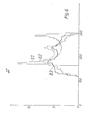
- Fig. 6 shows the material distribution of a laid sliver in a can according to the laying process mentioned above.
- a 600 mm diameter jug was used.
- the can radius is plotted as the abscissa and the fill quantity of sliver material is plotted as the ordinate.
- the thin, solid line 81 shows the tape deposit distribution in the case of a rotating funnel wheel 31 with a rotating can 11, which is not subject to any lateral displacement. There is a first large accumulation of material in an area with a radius of approx. 170 mm to 180 mm and a second accumulation in an area with a radius of approx. 280 mm to 290 mm.
- the dashed line 82 relates to the case in which the can 11 additionally carries out a lateral displacement.
- the band distribution is much better, the extreme peaks are eliminated.
- the thick, solid line 83 represents the conditions in the procedure according to the present invention, e.g. when using the device shown in FIGS. 1 and 2. It can be seen that, in addition to the above-mentioned tape deposit in the form of cycloid loops with precisely specified lateral distances, the distribution is further improved. In addition to a further reduction of the tips shown in FIG. 6, a strong improvement in the degree of filling is obtained in an inner area with radius values of approximately 130 mm to 170 mm and in an outer area with radius values between approximately 250 mm and 290 mm. The distribution according to the thick, solid line applies above all to a tape deposit "around the hole". It is less pronounced when placed on the hole.
- V-belt variator shown has the advantage that the device according to the invention takes up little space in height. This greatly facilitates access, which is particularly important with regard to changing the can.
- the invention is not restricted to this type of variator, and other types of translation devices can also be used.
- An optimal value is a lateral displacement that takes place over a distance that is 5-10% of the can diameter.
Landscapes
- Spinning Or Twisting Of Yarns (AREA)
- Coiling Of Filamentary Materials In General (AREA)
- Yarns And Mechanical Finishing Of Yarns Or Ropes (AREA)
Priority Applications (1)
| Application Number | Priority Date | Filing Date | Title |
|---|---|---|---|
| AT82102143T ATE14410T1 (de) | 1981-05-04 | 1982-03-17 | Verfahren und vorrichtung zum ablegen eines textilen faserbandes. |
Applications Claiming Priority (2)
| Application Number | Priority Date | Filing Date | Title |
|---|---|---|---|
| CH287381 | 1981-05-04 | ||
| CH2873/81 | 1981-05-04 |
Publications (2)
| Publication Number | Publication Date |
|---|---|
| EP0064584A1 true EP0064584A1 (fr) | 1982-11-17 |
| EP0064584B1 EP0064584B1 (fr) | 1985-07-24 |
Family
ID=4243491
Family Applications (1)
| Application Number | Title | Priority Date | Filing Date |
|---|---|---|---|
| EP82102143A Expired EP0064584B1 (fr) | 1981-05-04 | 1982-03-17 | Procédé et dispositif pour déposer un ruban de fibres textiles |
Country Status (6)
| Country | Link |
|---|---|
| US (1) | US4434532A (fr) |
| EP (1) | EP0064584B1 (fr) |
| JP (1) | JPS57184067A (fr) |
| AT (1) | ATE14410T1 (fr) |
| DE (1) | DE3264845D1 (fr) |
| IN (1) | IN158729B (fr) |
Cited By (5)
| Publication number | Priority date | Publication date | Assignee | Title |
|---|---|---|---|---|
| FR2587316A1 (fr) * | 1985-07-10 | 1987-03-20 | Truetzschler & Co | Appareil d'entrainement d'un dispositif de delivrance et d'emmagasinage de ruban de fibres a pot tournant de filature, pour carde ou banc d'etirage par exemple. |
| DE3618858A1 (de) * | 1986-06-04 | 1987-12-10 | Zinser Textilmaschinen Gmbh | Verfahren und vorrichtung zum ablegen von faserband zu einem zylindrischen bandpaket |
| CH682396A5 (de) * | 1989-12-05 | 1993-09-15 | Rieter Ag Maschf | Verfahren und Vorrichtung zum Ablegen eines textilen Vorgarnes oder Faserbandes. |
| FR2723576A1 (fr) * | 1994-08-11 | 1996-02-16 | Truetzschler Gmbh & Co Kg | Procede et dispositif de depot d'un ruban de fibres textiles dans un pot a rubans, en particulier sur un banc d'etirage |
| US5595049A (en) * | 1994-08-11 | 1997-01-21 | Trutzschler Gmbh & Co. Kg | Method and apparatus for depositing sliver from a sliver-producing machine into a coiler can |
Families Citing this family (2)
| Publication number | Priority date | Publication date | Assignee | Title |
|---|---|---|---|---|
| DE102006044682A1 (de) * | 2006-09-21 | 2008-03-27 | Rieter Ingolstadt Spinnereimaschinenbau Ag | Vorrichtung für eine Spinnereivorbereitungsmaschine sowie Spinnereivorbereitungsmaschine |
| CN111394837A (zh) * | 2020-04-09 | 2020-07-10 | 青岛宏大纺织机械有限责任公司 | 一种圈条器条筒增容装置 |
Citations (4)
| Publication number | Priority date | Publication date | Assignee | Title |
|---|---|---|---|---|
| US2695429A (en) * | 1953-02-20 | 1954-11-30 | Davis & Furber | Sliver coiler |
| GB759575A (en) * | 1953-08-18 | 1956-10-17 | Continental Can Co | Improvements in or relating to a method of packaging wire and a machine for carrying out the method |
| GB1459752A (en) * | 1973-01-12 | 1976-12-31 | Smiths Industries Ltd | Apparatus for and methods of manufacturing tubing |
| DE2802216A1 (de) * | 1978-01-19 | 1979-07-26 | Schlafhorst & Co W | Verfahren und vorrichtung zum ablegen von lunte in eine rotierende kanne |
Family Cites Families (2)
| Publication number | Priority date | Publication date | Assignee | Title |
|---|---|---|---|---|
| DE1510232C3 (de) | 1964-04-15 | 1974-11-28 | Schubert & Salzer Maschinenfabrik Ag, 8070 Ingolstadt | Verfahren und Vorrichtung zum Verziehen und Drehen von Faserbändern |
| CH627423A5 (de) | 1978-03-03 | 1982-01-15 | Rieter Ag Maschf | Antrieb einer kanne fuer die ablage von textilen faserbaendern in spinnereimaschinen. |
-
1982
- 1982-03-17 AT AT82102143T patent/ATE14410T1/de not_active IP Right Cessation
- 1982-03-17 DE DE8282102143T patent/DE3264845D1/de not_active Expired
- 1982-03-17 EP EP82102143A patent/EP0064584B1/fr not_active Expired
- 1982-03-22 IN IN318/CAL/82A patent/IN158729B/en unknown
- 1982-04-16 JP JP57062625A patent/JPS57184067A/ja active Granted
- 1982-05-04 US US06/374,880 patent/US4434532A/en not_active Expired - Lifetime
Patent Citations (4)
| Publication number | Priority date | Publication date | Assignee | Title |
|---|---|---|---|---|
| US2695429A (en) * | 1953-02-20 | 1954-11-30 | Davis & Furber | Sliver coiler |
| GB759575A (en) * | 1953-08-18 | 1956-10-17 | Continental Can Co | Improvements in or relating to a method of packaging wire and a machine for carrying out the method |
| GB1459752A (en) * | 1973-01-12 | 1976-12-31 | Smiths Industries Ltd | Apparatus for and methods of manufacturing tubing |
| DE2802216A1 (de) * | 1978-01-19 | 1979-07-26 | Schlafhorst & Co W | Verfahren und vorrichtung zum ablegen von lunte in eine rotierende kanne |
Cited By (6)
| Publication number | Priority date | Publication date | Assignee | Title |
|---|---|---|---|---|
| FR2587316A1 (fr) * | 1985-07-10 | 1987-03-20 | Truetzschler & Co | Appareil d'entrainement d'un dispositif de delivrance et d'emmagasinage de ruban de fibres a pot tournant de filature, pour carde ou banc d'etirage par exemple. |
| DE3618858A1 (de) * | 1986-06-04 | 1987-12-10 | Zinser Textilmaschinen Gmbh | Verfahren und vorrichtung zum ablegen von faserband zu einem zylindrischen bandpaket |
| CH682396A5 (de) * | 1989-12-05 | 1993-09-15 | Rieter Ag Maschf | Verfahren und Vorrichtung zum Ablegen eines textilen Vorgarnes oder Faserbandes. |
| FR2723576A1 (fr) * | 1994-08-11 | 1996-02-16 | Truetzschler Gmbh & Co Kg | Procede et dispositif de depot d'un ruban de fibres textiles dans un pot a rubans, en particulier sur un banc d'etirage |
| US5561889A (en) * | 1994-08-11 | 1996-10-08 | Trutzschler Gmbh & Co. Kg | Method and apparatus for altering angular velocity of a coiler head |
| US5595049A (en) * | 1994-08-11 | 1997-01-21 | Trutzschler Gmbh & Co. Kg | Method and apparatus for depositing sliver from a sliver-producing machine into a coiler can |
Also Published As
| Publication number | Publication date |
|---|---|
| ATE14410T1 (de) | 1985-08-15 |
| US4434532A (en) | 1984-03-06 |
| JPH0224749B2 (fr) | 1990-05-30 |
| IN158729B (fr) | 1987-01-10 |
| JPS57184067A (en) | 1982-11-12 |
| EP0064584B1 (fr) | 1985-07-24 |
| DE3264845D1 (en) | 1985-08-29 |
Similar Documents
| Publication | Publication Date | Title |
|---|---|---|
| EP0383246B2 (fr) | Procédé et appareil pour alimenter les flocons de fibres en quantité donnée | |
| EP1902990B1 (fr) | Dispositif pour une machine de prétraitement de filature | |
| EP0064584B1 (fr) | Procédé et dispositif pour déposer un ruban de fibres textiles | |
| EP0289009A1 (fr) | Procédé et dispositif pour la surveillance et le maintien d'une qualité de fil prédéterminée | |
| DE2421401C3 (de) | Vorrichtung zum Verteilen eines Fadenbündels bei der Spinnvlies-Herstellung | |
| DE19853192A1 (de) | Vorrichtung an einer faserverarbeitenden Textilmaschine zur Führung eines Faserverbandes | |
| CH690619A5 (de) | Vorrichtung und Verfahren zum Herstellen von Kurzketten. | |
| DE69411429T2 (de) | Verfahren zum Herstellen von konischen Wickeln fadenförmigen Gutes sowie damit erhältliche Wickel | |
| EP0365856B1 (fr) | Dispositif de courroie transversal à la sortie d'une machine de cardage | |
| DE2809661A1 (de) | Vorrichtung zum abziehen, speichern und ablegen von endlosen filament-, strang- oder kabelmaterial | |
| DE1290853B (de) | Anlage zum Speisen einer Kardengruppe | |
| DE3447506C2 (fr) | ||
| CH616183A5 (en) | Process for forming a lap web of constant weight per unit length and an apparatus for carrying out the process | |
| CH663039A5 (de) | Verfahren und vorrichtung zur wahlweisen freigabe einer vorbestimmten schussfadenlaenge ins webfach einer schuetzenlosen webmaschine. | |
| DE102010026189A1 (de) | Garnwickelmaschine und Garnwickelverfahren | |
| EP0394773B1 (fr) | Dispositif de mise en pots | |
| AT200703B (de) | Maschine zum gleichzeitigen gegenläufigen Wickeln zweier Fäden um einen Dorn | |
| EP0246183A1 (fr) | Dispositif pour former et déposer en continu des spires de fil | |
| DE3822925A1 (de) | Verfahren und vorrichtung zum herstellen eines gedrehten fadens in einem friktionsspinnaggregat | |
| CH250402A (de) | Sortiermaschnie für Plättchen. | |
| DE102004011690A1 (de) | Vorrichtung zur flächigen Ablage von Fasermaterial, insbesondere Mineralfasermaterial | |
| DE1454741C (de) | Einrichtung zum Zufuhren von faserigem Material in den Walzenspalt eines Kalanders | |
| AT409867B (de) | Einrichtung zum heben von fasergut | |
| DE3212580A1 (de) | Rundstrick- oder rundwirkmaschine zur herstellung von strick- oder wirkwaren mit eingekaemmten fasern | |
| DE19524663A1 (de) | Verfahren und Vorrichtung zum Changieren von faden- oder bändchenförmigem Spulgut |
Legal Events
| Date | Code | Title | Description |
|---|---|---|---|
| PUAI | Public reference made under article 153(3) epc to a published international application that has entered the european phase |
Free format text: ORIGINAL CODE: 0009012 |
|
| AK | Designated contracting states |
Designated state(s): AT BE CH DE FR GB IT NL |
|
| 17P | Request for examination filed |
Effective date: 19830317 |
|
| ITF | It: translation for a ep patent filed | ||
| GRAA | (expected) grant |
Free format text: ORIGINAL CODE: 0009210 |
|
| AK | Designated contracting states |
Designated state(s): AT BE CH DE FR GB IT LI NL |
|
| REF | Corresponds to: |
Ref document number: 14410 Country of ref document: AT Date of ref document: 19850815 Kind code of ref document: T |
|
| REF | Corresponds to: |
Ref document number: 3264845 Country of ref document: DE Date of ref document: 19850829 |
|
| ET | Fr: translation filed | ||
| PLBE | No opposition filed within time limit |
Free format text: ORIGINAL CODE: 0009261 |
|
| STAA | Information on the status of an ep patent application or granted ep patent |
Free format text: STATUS: NO OPPOSITION FILED WITHIN TIME LIMIT |
|
| 26N | No opposition filed | ||
| PGFP | Annual fee paid to national office [announced via postgrant information from national office to epo] |
Ref country code: BE Payment date: 19910220 Year of fee payment: 10 |
|
| PGFP | Annual fee paid to national office [announced via postgrant information from national office to epo] |
Ref country code: AT Payment date: 19910226 Year of fee payment: 10 |
|
| PGFP | Annual fee paid to national office [announced via postgrant information from national office to epo] |
Ref country code: NL Payment date: 19910331 Year of fee payment: 10 |
|
| PGFP | Annual fee paid to national office [announced via postgrant information from national office to epo] |
Ref country code: GB Payment date: 19920217 Year of fee payment: 11 |
|
| PGFP | Annual fee paid to national office [announced via postgrant information from national office to epo] |
Ref country code: FR Payment date: 19920221 Year of fee payment: 11 |
|
| PG25 | Lapsed in a contracting state [announced via postgrant information from national office to epo] |
Ref country code: AT Effective date: 19920317 |
|
| PG25 | Lapsed in a contracting state [announced via postgrant information from national office to epo] |
Ref country code: BE Effective date: 19920331 |
|
| BERE | Be: lapsed |
Owner name: MASCHINENFABRIK RIETER A.G. Effective date: 19920331 |
|
| PG25 | Lapsed in a contracting state [announced via postgrant information from national office to epo] |
Ref country code: NL Effective date: 19921001 |
|
| NLV4 | Nl: lapsed or anulled due to non-payment of the annual fee | ||
| PGFP | Annual fee paid to national office [announced via postgrant information from national office to epo] |
Ref country code: CH Payment date: 19930219 Year of fee payment: 12 |
|
| PG25 | Lapsed in a contracting state [announced via postgrant information from national office to epo] |
Ref country code: GB Effective date: 19930317 |
|
| ITTA | It: last paid annual fee | ||
| GBPC | Gb: european patent ceased through non-payment of renewal fee |
Effective date: 19930317 |
|
| PG25 | Lapsed in a contracting state [announced via postgrant information from national office to epo] |
Ref country code: FR Effective date: 19931130 |
|
| REG | Reference to a national code |
Ref country code: FR Ref legal event code: ST |
|
| PG25 | Lapsed in a contracting state [announced via postgrant information from national office to epo] |
Ref country code: LI Effective date: 19940331 Ref country code: CH Effective date: 19940331 |
|
| REG | Reference to a national code |
Ref country code: CH Ref legal event code: PL |
|
| PGFP | Annual fee paid to national office [announced via postgrant information from national office to epo] |
Ref country code: DE Payment date: 19950211 Year of fee payment: 14 |
|
| PG25 | Lapsed in a contracting state [announced via postgrant information from national office to epo] |
Ref country code: DE Effective date: 19961203 |