EP0064746A2 - Capteur de la direction de lumière solaire - Google Patents
Capteur de la direction de lumière solaire Download PDFInfo
- Publication number
- EP0064746A2 EP0064746A2 EP82104000A EP82104000A EP0064746A2 EP 0064746 A2 EP0064746 A2 EP 0064746A2 EP 82104000 A EP82104000 A EP 82104000A EP 82104000 A EP82104000 A EP 82104000A EP 0064746 A2 EP0064746 A2 EP 0064746A2
- Authority
- EP
- European Patent Office
- Prior art keywords
- photosensor
- cylindrical body
- output signal
- flange
- sunbeams
- Prior art date
- Legal status (The legal status is an assumption and is not a legal conclusion. Google has not performed a legal analysis and makes no representation as to the accuracy of the status listed.)
- Granted
Links
Images

Classifications
-
- G—PHYSICS
- G01—MEASURING; TESTING
- G01S—RADIO DIRECTION-FINDING; RADIO NAVIGATION; DETERMINING DISTANCE OR VELOCITY BY USE OF RADIO WAVES; LOCATING OR PRESENCE-DETECTING BY USE OF THE REFLECTION OR RERADIATION OF RADIO WAVES; ANALOGOUS ARRANGEMENTS USING OTHER WAVES
- G01S3/00—Direction-finders for determining the direction from which infrasonic, sonic, ultrasonic or electromagnetic waves, or particle emission, not having a directional significance, are being received
- G01S3/78—Direction-finders for determining the direction from which infrasonic, sonic, ultrasonic or electromagnetic waves, or particle emission, not having a directional significance, are being received using electromagnetic waves other than radio waves
- G01S3/782—Systems for determining direction or deviation from predetermined direction
- G01S3/783—Systems for determining direction or deviation from predetermined direction using amplitude comparison of signals derived from static detectors or detector systems
Definitions
- the present invention relates to a sunlight direction sensor for detecting the direction of the sun.
- the present invention has been made in consideration of the above problem and has its object to provide a sunlight direction sensor which is mounted in a solar energy collector device to cause the device to automatically follow the sun.
- a sunlight direction sensor comprising a cylindrical body, a nontransparent flange disposed at an upper end of cylindrical body and having a circumferential portion whose diameter is smaller than an inner diameter of the cylindrical body, a first photosensor which is arranged on the nontransparent flange or at a substantially center of a lower end of the cylindrical body, and at least one pair of each of second and third photosensors which are symmetrically arranged at the lower end of the cylindrical body, inner edges of the one pair ot each of the second and third photosensors corresponding to an inner periphery of the flange.
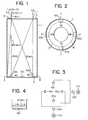
- Fig. 1 is a side-sectional view of a sunlight direction sensor previously proposed by the same applicant.
- Fig. 2 is a sectional view taken along the line II - II in Fig. 1.
- a nontransparent upper flange 2 and a nontransparent lower flange 3 are formed at the top of a nontransparent cylindrical body 1 and at the bottom thereof.
- At least one pair of photosensors 4X 1 and 4X 2 or 4Yl and 4Y 2 are arranged at equal angular intervals on the upper surface of the flange 3 in such a manner that photosensors 4X, and 4X 2 are symmetrical with respect to the axis of the cylindrical body 1.
- the photosensors 4Y 1 and 4Y 2 are also symmetrical with respect to the axis. Distances between inner edges Xa and Xa and between inner edges Ya and Ya of the photosensors are the same as the inner diameter of the flange 2.
- the pairs of photosensors are preferably arranged perpendicularly to each other. When the axis of the cylindrical body 1 is parallel to sunbeams, they are not directly incident on the photosensors 4X 1 , 4X2, 4Y 1 and 4Y 2 . Thus, the photosensors generate an output in accordance with indirectly incident sunbeams.
- outputs from the photosensors 4X 1 and 4X 2 are compared with each other in a differential amplifier 10X. If a motor 11X is driven to eliminate the difference, the solar energy collector device is rotated about a Y-axis (line connecting the photosensors 4Y 1 and 4Y 2 ) to be directed toward the sun, resulting in optimal conditions for collecting solar energy. If incident sunbeams deviate along the Y -axis, outputs from the photosensors 4Y, and 4Y 2 are compared with each other in a differential amplifier 10Y and a motor 11Y is driven to eliminate the difference. Therefore, the solar energy collector device is then pivoted about an X-axis (line connecting the photosensors 4X 1 and 4X 2 ) to be directed toward the sun.
- a photosensor 5 is arranged on the upper surface of the flange 2 and detects the presence or absence of the sunbeams. Only when the photosensor 5 detects the presence of the sunbeams, the solar energy collector device follows the sun. However, when the sunbeams are not radiated, for example, at night, the solar energy collector device stops following the sun. Referring to Fig.
- the photosensor 5 is defined as a sensor for detecting the total amount of sunbeams
- the sensor 4X is defined as a sensor for detecting the amount of direct beams from the sun (or a sensor for detecting the amount of indirect beams trom the sun)
- the photosensor 4X 2 is defined as a sensor for detecting the amount of indirect beams from the sun (or a sensor for detecting the amount of direct beams from the sun when the photosensor 4X 1 is used as the sensor for detecting the amount of indirect beams from the sun).
- a total amount S (lux) of sunbeams, an amount D (lux) of direct beams from the sun, and an amount I (lux) of indirect beams from the sun have the following relation:
- a ratio (D/I) of the amount of direct beams from the sun to the indirect beams from the sun is defined as ⁇ , the following relation is given:
- an output signal associated with the total amount S of sunbeams detected by the photosensor 5 is defined as L 0 (mV)
- an output signal associated with the amount D of beams detected by the photosensor 4X 1 is defined as L 1 (mV)
- an output signal associated with the amount I of beams detected by the photosensor 4X 2 is defined as L 2 .
- One edge of the photosensor 4X 1 or 4X 2 which is in contact with the outer periphery of the luminous flux in the cylindrical body 1 is defined as 0 and the other edge thereof which is in contact with the inner periphery of the cylindrical body 1 is defined as 1.
- a ratio of the width of the luminous flux fallen on the photosensor 4X 1 to that of the photosensor 4X 1 is defined as a.
- the ratio a is expressed by only the measurable values L o , L 1 and L 2 and is independently of the ratio B and the conversion coefficient 6. If the sunbeams incident on the cylindrical body 1 are within an angular range corresponding to the ratio within the range of 0 ⁇ a ⁇ 1, the incident angle of the sunbeams is calculated by only the output signals from the photosensors 5, 4X 1 and 4X 2 , as shown in relation (5). If values of the output signals in mV are substituted in relation (5), an angle by which the cylindrical body 1 is deviated from the sunbeams can be measured. Then, the cylindrical body 1 is rotated though the measured angle, preventing overhunting by a stepping motor effectively.
- the present invention has been made to further improve the conventional technique for calculation of the ratio a described above.
- sensitivity of the photosensor 5 (first photosensor) disposed on the flange 2 may differ from that of the photosensors 4X l (second photosensor) and 4X 2 (third photosensor) arranged on the flange 3.
- the amount of sunbeams fallen on the photosensor on the flange 2 may differ from that of sunbeams fallen on the photosensors on the flange 3. More specifically, the amount of sunbeams incident on the photosensor 5 on the flange 3 is smaller than that of sunbeams incident on the photosensors 4X 1 and 4X 2 .
- the output signal from the photosensor 5 is smaller than that from the photosensor 4X 1 or 4X 2 .
- the output signals from these photosensors do not satisfy relation (5).
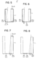
- the present invention has been made to eliminate the drawback of the conventional method. Assume that sunbeams are fallen on the entire surface of the second or third sensor 4X 1 or 4X 2 and an output signal therefrom is defined as L 1 and the output signal from the first photosensor 5 is defined as L 0 .
- a ratio L 1 /L 0 is defined as ⁇
- the total amount of sunbeams incident on the flange 2 is S 0
- the amount of beams incident directly from the sun is defined as D
- the amount of beams incident indirectly from the sun is defined as I
- the ratio a can be accurately determined.
- Fig. 6 is a view of a sunlight direction sensor according to a second embodiment of the present invention.
- the sunlight direction sensor in Fig. 6 is substantially the same as that in Fig. 5 except that the photosensor 5 is disposed at the center of the bottom of the cylindrical body 1 and designated as 5a.
- the sunlight direction sensor with the above arrangement can obtain the same effects as that in Fig. 5. In other words, the ratio a is determined accurately. If an output from the photosensor 5a is defined as Lc (mV), a correction coefficient between the photosensors 5a and 4X 1 or 4X 2 is defined as ⁇ a, the following relations are given:
- the ratio a is more accurately determined if the correction coefficient ⁇ a is determined in advance.
- Fig. 7 is a schematic view of a sunlight direction sensor according to a third embodiment of the present invention.
- the sunlight direction sensor shown in Fig. 7 is substantially the same as that shown in Fig. 5 except that the photosensors 4X 1 and 4X 2 are arranged within the luminous flux in the cylindrical body 1. With the above arrangement, the ratio a can be accurately determined. In the same manner as described above,
- Fig. 8 is a schematic view of a sunlight direction sensor according to a fourth embodiment of the present invention.
- the sunlight direction sensor shown in Fig. 8 is substantially the same as that shown in Fig. 7 except that the photosensor 5 is disposed at the center of the bottom of the cylindrical body 1 and defined as 5a.
- a correction coefficient between the photosensor 5a and 5X 1 or 4X 2 is defined as Xc and the total amount of sunbeams within the cylindrical body 1 is defined as Sc.
- the ratio a can be accurately determined in the same manner as in the previous embodiments.
- the sunlight direction sensor according to the present invention is easily manufactured at low cost and measures the direction of the incident sunbeams accurately.
- Fig. 9 is a perspective view of the overall arrangement of a sunlight direction sensor according to a fifth embodiment of the present invention
- Fig. 10 is a sectional view thereof taken along the line X - X in F ig..9
- Fig. 11 is a plan view thereof
- Fig. 12 is a sectional view thereof taken along the line XII - XII in Fig. 10.
- a flange 102 is formed at the upper end of a prism-shaped or round-shaped cylindrical body 101.
- Photosensors X 1 to X 4 are arranged on a bottom plate 104.
- a photosensor X c is disposed at the center of the bottom plate 104.
- a polygonal or circular window 103 is formed at the upper end of the cylindrical body 101.
- the photosensors X 1 and X 2 , and X 3 and X 4 are symmetrical in respect with the central axis of the cylindrical body 101, respectively. Further, these photosensors are arranged at equal angular intervals with each other, as shown in Fig. 12. Inner edges of the photosensors X o to X 4 correspond to the inner edge of the flange 102. Therefore, if sunbeams perpendicular to the plane of the flange 102 are incident thereon, the photosensors X o to X 4 are on the ouLcrline of the shade 102.
- the solar energy collector device which mounts the sunlight direction sensor therein is oriented toward the sun.
- the intensity of the beams I is high at the center of the cylindrical body 101 and is low at the outer periphery thereof, as shown in Fig. 13. If the difference between the central intensity and the peripheral intensity of the beams is not compensated corrected, the orientation of the sunlight direction sensor through which the beams D pass cannot be measured accurately. In other words, the ratio a cannot be accurately determined.
- a method is provided wherein an angular deviation of the axis of the cylindrical body of the sunlight direction sensor from the direction of the sunbeams is detected as a numeric value accurately.
- the photosensor X o is arranged on the flange 102 of the sunlight direction sensor shown in Figs. 9 to 12.
- the total amount of sunbeams is defined as S 0
- the amount of direct beams from the sun is defined as D 0
- the output signal from the photosensor X o is defined as L 0
- a ratio D 0 /S 0 is defined as ⁇ 0 .
- a total amount S 1 of sunbeams fallen on the photosensor X 1 is given by the following relation if the ratio a is larger than 0 and less than 1: where L 1 is the output signal (mV) and ⁇ 1 is the photoelectric conversion coefficient.
- L 1 is the output signal (mV) and ⁇ 1 is the photoelectric conversion coefficient.
- the indirect beams from the sun are incident on the entire surface of the photosensor X 1 , so the following relation is established: where I 1 is the total amount of the indirect beams from the sun which are incident on the photosensor X 1 . This amount is substantially equal to that of indirect beams from the sun which are incident on the photosensor X 2 , that is, to the total amount of sunbeams S 2 incident on the photosensor X 2 .
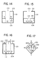
- Fig. 14 is a side-sectional view of a sunlight direction sensor according to a sixth embodiment of the present invention.
- a second flange 106 having a small window 105 which is equal to or larger than the window 103 of the flange 102 is disposed at the intermediate portion of the cylindrical body 101.
- the photosensors X 1 to X 4 are arranged on the flange 106 and the sensor X c is disposed at the center of the inner bottom surface of the cylindrical body 101.
- the amount of indirectly radiated sunbeams incident on the photosensor X c is equal to that of indirectly radiated sunbeams incident on the photosensors X 1 to X 4 becomes 1 in relation (113).
- relation (117) is expressed as follows: Without measuring a in advance, the ratio a can be measured only by the output signals from the photosensors.
- Fig. 15 is a sectional view of a sunlight direction sensor according to a seventh embodiment of the present invention.
- the second flange 106 is formed at the intermediate portion of the cylindrical body 101 in the same manner as in Fig. 14.
- the photosensors X 1 to X 4 and X c are arranged on the inner bottom surface of the cylindrical body 101.
- the inner edges of the photosensors X 1 to X 4 correspond to the inner periphery of the second flange 106.
- a ratio ⁇ c / ⁇ l of the sensitivity (1/6 ) of the photosensor X c on which the direct sunbeams are incident to the sensitivity (l/ ⁇ l ) of the photosensor X 1 (X 2 , X 3 or X 4 ) is determined as 5 in humid areas and 10 in the dry areas in normal operation in consideration of the ratio (1 - ⁇ 0 ) of average of indirectly fallen sunbeams, the intensity of the sunbeams does not influence the measurement greatly and the measuring range by the photosensors is determined to be optimal.
- the sunbeams are instantaneously dispersed when the sun is hidden behind the clouds.
- the dispersed sunbeams become nonuniformly incident on the photosensors X 1 to X 4 with a time lag.
- the solar energy collector device is quickly controlled by the unbalanced outputs from the photosensors, resulting in overhunting.
- a sunlight direction sensor according to an eighth embodiment of the present invention is described with reference to Figs. 16 and 17.
- Fig. 16 is a side-sectional view of the sunlight direction sensor and
- Fig. 17 is a plan view thereof.
- the photosensors X 1 to X 4 are arranged so that the line perpendicular to the plane of a flange 202 are depending from the inner periphery of a window 203 corresponds to intermediate portions (edge portions of the photosensors in the embodiment shown in Figs. 9 to 12) of the photosensors x 1 to X4 .
- the operation point of the photosensors is unstable.
- the line perpendicular to the plane of the window 203 depending from its inner periphery may correspond to any intermediate point on the photosensors X 1 to X 4 .
- the accuracy of measurement is independently of unstable material conditions. Only if a width l of the sensors X 1 to X 4 need be finished with high precision.
- the position on the photosensor which matches the line perpendicular to the plane of the window 203 is defined as 0.
- the boundary for determining the presence or absence of directly radiated sunbeams is located on the intermediate points of the photosensors X 1 to X 4 , respectively.
- the output signals from the photosensors are linearly changed upon movement of the boundary, respectively.
- the sunlight direction sensor is not influenced by an external disturbance greatly. Therefore, the N/S ratio and linearity of the output of the photosensors are improved greatly, resulting in easy controllability.
Landscapes
- Physics & Mathematics (AREA)
- Electromagnetism (AREA)
- Engineering & Computer Science (AREA)
- General Physics & Mathematics (AREA)
- Radar, Positioning & Navigation (AREA)
- Remote Sensing (AREA)
- Photometry And Measurement Of Optical Pulse Characteristics (AREA)
Applications Claiming Priority (6)
| Application Number | Priority Date | Filing Date | Title |
|---|---|---|---|
| JP69781/81 | 1981-05-09 | ||
| JP56069781A JPS57184934A (en) | 1981-05-09 | 1981-05-09 | Direction sensor for incident sunlight |
| JP99993/81 | 1981-06-26 | ||
| JP56099993A JPS581110A (ja) | 1981-06-26 | 1981-06-26 | 太陽光方向センサ |
| JP17237/82 | 1982-02-05 | ||
| JP1723782A JPH0245812B2 (ja) | 1982-02-05 | 1982-02-05 | Taiyokohokosensa |
Publications (3)
| Publication Number | Publication Date |
|---|---|
| EP0064746A2 true EP0064746A2 (fr) | 1982-11-17 |
| EP0064746A3 EP0064746A3 (en) | 1983-01-19 |
| EP0064746B1 EP0064746B1 (fr) | 1987-08-19 |
Family
ID=27281737
Family Applications (1)
| Application Number | Title | Priority Date | Filing Date |
|---|---|---|---|
| EP82104000A Expired EP0064746B1 (fr) | 1981-05-09 | 1982-05-07 | Capteur de la direction de lumière solaire |
Country Status (4)
| Country | Link |
|---|---|
| US (1) | US4495408A (fr) |
| EP (1) | EP0064746B1 (fr) |
| AU (1) | AU557732B2 (fr) |
| DE (2) | DE64746T1 (fr) |
Cited By (4)
| Publication number | Priority date | Publication date | Assignee | Title |
|---|---|---|---|---|
| EP0101055A1 (fr) * | 1982-08-11 | 1984-02-22 | Kei Mori | Dispositif pour détecter une source mobile de lumière |
| EP0326090A3 (en) * | 1988-01-28 | 1990-06-06 | Standard Elektrik Lorenz Aktiengesellschaft | Circuit arrangement for weighting the output signals of a photodiode array |
| ES2117550A1 (es) * | 1994-12-23 | 1998-08-01 | Deutsche Forsch Luft Raumfahrt | Dispositivo para la concentracion de radiacion solar. |
| EP2348261A4 (fr) * | 2008-11-17 | 2012-08-01 | Tm Tech Co Ltd | Support de capteur optique pour suivre la lumière solaire |
Families Citing this family (24)
| Publication number | Priority date | Publication date | Assignee | Title |
|---|---|---|---|---|
| US4687923A (en) * | 1985-06-03 | 1987-08-18 | Motorola, Inc. | Method for determining the direction of a radiation source |
| US4649899A (en) * | 1985-07-24 | 1987-03-17 | Moore Roy A | Solar tracker |
| DE8705296U1 (de) * | 1987-04-09 | 1988-08-04 | Heimann Gmbh, 6200 Wiesbaden | Infrarotdetektor |
| US5512742A (en) * | 1993-12-28 | 1996-04-30 | Mattson; Brad A. | Solar energy and tracking system |
| US5957375A (en) * | 1996-10-28 | 1999-09-28 | Eaton Corporation | Sunload sensor for automatic climate control systems |
| CN100434861C (zh) * | 2005-06-09 | 2008-11-19 | 王成伟 | 光跟踪传感器 |
| ES2307465T3 (es) * | 2005-06-09 | 2014-03-31 | Chengwei Wang | Sensor de seguimiento de luz y sistema de seguimiento de la luz solar del mismo |
| US7622666B2 (en) * | 2005-06-16 | 2009-11-24 | Soliant Energy Inc. | Photovoltaic concentrator modules and systems having a heat dissipating element located within a volume in which light rays converge from an optical concentrating element towards a photovoltaic receiver |
| WO2007044385A2 (fr) * | 2005-10-04 | 2007-04-19 | Practical Instruments, Inc. | Systemes auto-alimentes et procedes utilisant des cellules solaires auxiliaires |
| US20070193620A1 (en) * | 2006-01-17 | 2007-08-23 | Hines Braden E | Concentrating solar panel and related systems and methods |
| CN101375112A (zh) * | 2006-01-17 | 2009-02-25 | 索利安特能源公司 | 用于光学聚光器的混合式主光学部件 |
| US20080135096A1 (en) * | 2006-09-30 | 2008-06-12 | Johnson Richard L | Optical concentrators having one or more line foci and related methods |
| US20080128586A1 (en) * | 2006-10-13 | 2008-06-05 | Johnson Richard L | Sun sensor assembly and related method of using |
| US20090000662A1 (en) * | 2007-03-11 | 2009-01-01 | Harwood Duncan W J | Photovoltaic receiver for solar concentrator applications |
| ES2538815T3 (es) * | 2008-05-16 | 2015-06-24 | Suncore Photovoltaics Incorporated | Panel solar fotovoltaico de concentración |
| US8338694B2 (en) | 2008-06-07 | 2012-12-25 | Sun Synchrony | Solar energy collection system |
| CN100575870C (zh) * | 2008-07-21 | 2009-12-30 | 北京交通大学 | 追踪太阳感光器 |
| EP2371004B1 (fr) | 2008-12-03 | 2015-07-29 | Sun Synchrony, Inc. | Système de collecte d'énergie solaire |
| EP2577183B1 (fr) | 2010-05-28 | 2018-10-10 | SolarCity Corporation | Système de repositionnement héliostat |
| US8442790B2 (en) | 2010-12-03 | 2013-05-14 | Qbotix, Inc. | Robotic heliostat calibration system and method |
| US9689957B2 (en) | 2012-05-29 | 2017-06-27 | Solarcity Corporation | Solar tracking system using periodic scan patterns with a shielding tube |
| US8878113B2 (en) | 2012-05-29 | 2014-11-04 | Qbotix, Inc. | Solar tracking system using periodic scan patterns with a shielding tube |
| US20150136944A1 (en) * | 2013-11-21 | 2015-05-21 | Avraham Segev | Sunlight tracking sensor and system |
| CN103869832B (zh) * | 2014-03-29 | 2016-04-13 | 安庆师范学院 | 光源自动追踪式太阳能采集装置及其控制方法 |
Family Cites Families (18)
| Publication number | Priority date | Publication date | Assignee | Title |
|---|---|---|---|---|
| US3268185A (en) * | 1962-04-02 | 1966-08-23 | Bendix Corp | Light sensing device |
| US3229102A (en) * | 1962-05-31 | 1966-01-11 | Paul R Spencer | Radiation direction detector including means for compensating for photocell aging |
| US3406287A (en) * | 1963-06-26 | 1968-10-15 | Bendix Corp | Radiation sensitive device for detecting sun in a selected field of view |
| US3496367A (en) * | 1965-04-12 | 1970-02-17 | Bendix Corp | Light sensing device including means for sensing wide angle and fine angle light |
| US3370293A (en) * | 1966-02-02 | 1968-02-20 | Green Milton | Direction finder |
| US3435232A (en) * | 1966-03-03 | 1969-03-25 | Hewlett Packard Co | Beam position detector |
| US3599001A (en) * | 1967-05-22 | 1971-08-10 | Hughes Aircraft Co | Multifield sensor arrangement |
| US3783271A (en) * | 1971-09-27 | 1974-01-01 | Hughes Aircraft Co | Radiation tracking system |
| JPS50140934A (fr) * | 1974-03-27 | 1975-11-12 | ||
| US4003655A (en) * | 1975-04-17 | 1977-01-18 | The United States Of America As Represented By The Secretary Of The Army | Hybrid silicon avalanche quadrant detector |
| US3996460A (en) * | 1975-12-03 | 1976-12-07 | Smith Peter D | Solar tracking control system using shadow detection |
| US4041307A (en) * | 1976-06-07 | 1977-08-09 | Rca Corporation | Positioning a platform with respect to rays of a light source |
| IT1103059B (it) * | 1978-09-01 | 1985-10-14 | Gori & Zucchi Spa | Sistema inseguitore solare o di al tra sorgente di luce con ricerca automatica della massima irradiazione |
| US4179612A (en) * | 1979-01-12 | 1979-12-18 | Smith Peter D | Radiation tracking control |
| US4225781A (en) * | 1979-02-26 | 1980-09-30 | The United States Of America As Represented By The United States Department Of Energy | Solar tracking apparatus |
| US4302710A (en) * | 1979-11-01 | 1981-11-24 | Menser Industries | Sun tracking controller |
| US4355896A (en) * | 1980-06-27 | 1982-10-26 | Nasa | Cloud cover sensor |
| US4447718A (en) * | 1980-07-07 | 1984-05-08 | Kei Mori | Apparatus for collecting and concentrating solar light energy |
-
1982
- 1982-05-05 AU AU83300/82A patent/AU557732B2/en not_active Ceased
- 1982-05-07 DE DE198282104000T patent/DE64746T1/de active Pending
- 1982-05-07 EP EP82104000A patent/EP0064746B1/fr not_active Expired
- 1982-05-07 US US06/376,235 patent/US4495408A/en not_active Expired - Fee Related
- 1982-05-07 DE DE8282104000T patent/DE3277033D1/de not_active Expired
Cited By (4)
| Publication number | Priority date | Publication date | Assignee | Title |
|---|---|---|---|---|
| EP0101055A1 (fr) * | 1982-08-11 | 1984-02-22 | Kei Mori | Dispositif pour détecter une source mobile de lumière |
| EP0326090A3 (en) * | 1988-01-28 | 1990-06-06 | Standard Elektrik Lorenz Aktiengesellschaft | Circuit arrangement for weighting the output signals of a photodiode array |
| ES2117550A1 (es) * | 1994-12-23 | 1998-08-01 | Deutsche Forsch Luft Raumfahrt | Dispositivo para la concentracion de radiacion solar. |
| EP2348261A4 (fr) * | 2008-11-17 | 2012-08-01 | Tm Tech Co Ltd | Support de capteur optique pour suivre la lumière solaire |
Also Published As
| Publication number | Publication date |
|---|---|
| EP0064746A3 (en) | 1983-01-19 |
| US4495408A (en) | 1985-01-22 |
| DE64746T1 (de) | 1983-04-28 |
| AU557732B2 (en) | 1987-01-08 |
| DE3277033D1 (en) | 1987-09-24 |
| EP0064746B1 (fr) | 1987-08-19 |
| AU8330082A (en) | 1982-11-18 |
Similar Documents
| Publication | Publication Date | Title |
|---|---|---|
| EP0064746A2 (fr) | Capteur de la direction de lumière solaire | |
| CA1216452A (fr) | Detecteurs de sources lumineuses mobiles | |
| US5101570A (en) | Inclination angle detector | |
| US20080128586A1 (en) | Sun sensor assembly and related method of using | |
| JPH02236108A (ja) | 太陽センサ | |
| CA1232154A (fr) | Debitmetre de fluides | |
| EP0596982B1 (fr) | Systeme de determination du sens d'un rayonnement optique incident | |
| CN101995233A (zh) | 用于太阳精密跟踪的角度测量方法与数字式光电角度传感器 | |
| GB1460859A (en) | Apparatus for measuring surface stress by x-ray diffraction | |
| JPS57144409A (en) | Distance detector | |
| KR860000292B1 (ko) | 태양광 방향센서 | |
| JP2557051B2 (ja) | 太陽光方向センサ | |
| EP0312332B1 (fr) | Baromètre | |
| KR101725843B1 (ko) | 태양각 측정장치 | |
| US6087664A (en) | Process and device for measuring the radiation depth of radiation | |
| JPH0245812B2 (ja) | Taiyokohokosensa | |
| USH746H (en) | Solar reference flight roll position sensor | |
| JPS5918414A (ja) | 太陽光方向センサ | |
| JPS581110A (ja) | 太陽光方向センサ | |
| JP2818251B2 (ja) | 太陽センサ | |
| JPH0632569Y2 (ja) | 太陽光集光装置の角度制御用太陽位置センサ | |
| US4719344A (en) | Method of and apparatus for measuring amount of solar radiation received directly | |
| KR100295605B1 (ko) | 아날로그태양센서 | |
| JPS6468609A (en) | Charging state detecting method for concrete | |
| SU1456717A1 (ru) | Фотодатчик ориентации |
Legal Events
| Date | Code | Title | Description |
|---|---|---|---|
| PUAI | Public reference made under article 153(3) epc to a published international application that has entered the european phase |
Free format text: ORIGINAL CODE: 0009012 |
|
| 17P | Request for examination filed |
Effective date: 19820507 |
|
| AK | Designated contracting states |
Designated state(s): CH DE FR GB IT SE |
|
| PUAL | Search report despatched |
Free format text: ORIGINAL CODE: 0009013 |
|
| ITCL | It: translation for ep claims filed |
Representative=s name: BARZANO' E ZANARDO MILANO S.P.A. |
|
| AK | Designated contracting states |
Designated state(s): CH DE FR GB IT LI SE |
|
| EL | Fr: translation of claims filed | ||
| DET | De: translation of patent claims | ||
| ITF | It: translation for a ep patent filed | ||
| GRAA | (expected) grant |
Free format text: ORIGINAL CODE: 0009210 |
|
| AK | Designated contracting states |
Kind code of ref document: B1 Designated state(s): CH DE FR GB IT LI SE |
|
| REF | Corresponds to: |
Ref document number: 3277033 Country of ref document: DE Date of ref document: 19870924 |
|
| ET | Fr: translation filed | ||
| PLBE | No opposition filed within time limit |
Free format text: ORIGINAL CODE: 0009261 |
|
| STAA | Information on the status of an ep patent application or granted ep patent |
Free format text: STATUS: NO OPPOSITION FILED WITHIN TIME LIMIT |
|
| 26N | No opposition filed | ||
| PGFP | Annual fee paid to national office [announced via postgrant information from national office to epo] |
Ref country code: GB Payment date: 19890430 Year of fee payment: 8 |
|
| PGFP | Annual fee paid to national office [announced via postgrant information from national office to epo] |
Ref country code: SE Payment date: 19890523 Year of fee payment: 8 |
|
| ITTA | It: last paid annual fee | ||
| PG25 | Lapsed in a contracting state [announced via postgrant information from national office to epo] |
Ref country code: GB Effective date: 19900507 |
|
| PG25 | Lapsed in a contracting state [announced via postgrant information from national office to epo] |
Ref country code: SE Effective date: 19900508 |
|
| GBPC | Gb: european patent ceased through non-payment of renewal fee | ||
| EUG | Se: european patent has lapsed |
Ref document number: 82104000.3 Effective date: 19910115 |
|
| PGFP | Annual fee paid to national office [announced via postgrant information from national office to epo] |
Ref country code: FR Payment date: 19950517 Year of fee payment: 14 |
|
| PGFP | Annual fee paid to national office [announced via postgrant information from national office to epo] |
Ref country code: CH Payment date: 19950519 Year of fee payment: 14 |
|
| PGFP | Annual fee paid to national office [announced via postgrant information from national office to epo] |
Ref country code: DE Payment date: 19950630 Year of fee payment: 14 |
|
| PG25 | Lapsed in a contracting state [announced via postgrant information from national office to epo] |
Ref country code: LI Effective date: 19960531 Ref country code: CH Effective date: 19960531 |
|
| REG | Reference to a national code |
Ref country code: CH Ref legal event code: PL |
|
| PG25 | Lapsed in a contracting state [announced via postgrant information from national office to epo] |
Ref country code: FR Effective date: 19970131 |
|
| PG25 | Lapsed in a contracting state [announced via postgrant information from national office to epo] |
Ref country code: DE Effective date: 19970201 |
|
| REG | Reference to a national code |
Ref country code: FR Ref legal event code: ST |