EP0065210A2 - Verfahren zur Aufbereitung elektrischer Signale mit einer digitalen Filteranordnung - Google Patents
Verfahren zur Aufbereitung elektrischer Signale mit einer digitalen Filteranordnung Download PDFInfo
- Publication number
- EP0065210A2 EP0065210A2 EP82103859A EP82103859A EP0065210A2 EP 0065210 A2 EP0065210 A2 EP 0065210A2 EP 82103859 A EP82103859 A EP 82103859A EP 82103859 A EP82103859 A EP 82103859A EP 0065210 A2 EP0065210 A2 EP 0065210A2
- Authority
- EP
- European Patent Office
- Prior art keywords
- signals
- signal
- partial signals
- spectral
- digital filter
- Prior art date
- Legal status (The legal status is an assumption and is not a legal conclusion. Google has not performed a legal analysis and makes no representation as to the accuracy of the status listed.)
- Granted
Links
Images
Classifications
-
- H—ELECTRICITY
- H04—ELECTRIC COMMUNICATION TECHNIQUE
- H04K—SECRET COMMUNICATION; JAMMING OF COMMUNICATION
- H04K1/00—Secret communication
- H04K1/04—Secret communication by frequency scrambling, i.e. by transposing or inverting parts of the frequency band or by inverting the whole band
-
- G—PHYSICS
- G10—MUSICAL INSTRUMENTS; ACOUSTICS
- G10L—SPEECH ANALYSIS TECHNIQUES OR SPEECH SYNTHESIS; SPEECH RECOGNITION; SPEECH OR VOICE PROCESSING TECHNIQUES; SPEECH OR AUDIO CODING OR DECODING
- G10L21/00—Speech or voice signal processing techniques to produce another audible or non-audible signal, e.g. visual or tactile, in order to modify its quality or its intelligibility
- G10L21/02—Speech enhancement, e.g. noise reduction or echo cancellation
-
- H—ELECTRICITY
- H03—ELECTRONIC CIRCUITRY
- H03H—IMPEDANCE NETWORKS, e.g. RESONANT CIRCUITS; RESONATORS
- H03H17/00—Networks using digital techniques
- H03H17/02—Frequency selective networks
- H03H17/0283—Filters characterised by the filter structure
- H03H17/0286—Combinations of filter structures
- H03H17/0288—Recursive, non-recursive, ladder, lattice structures
-
- H—ELECTRICITY
- H04—ELECTRIC COMMUNICATION TECHNIQUE
- H04B—TRANSMISSION
- H04B1/00—Details of transmission systems, not covered by a single one of groups H04B3/00 - H04B13/00; Details of transmission systems not characterised by the medium used for transmission
- H04B1/66—Details of transmission systems, not covered by a single one of groups H04B3/00 - H04B13/00; Details of transmission systems not characterised by the medium used for transmission for reducing bandwidth of signals; for improving efficiency of transmission
- H04B1/667—Details of transmission systems, not covered by a single one of groups H04B3/00 - H04B13/00; Details of transmission systems not characterised by the medium used for transmission for reducing bandwidth of signals; for improving efficiency of transmission using a division in frequency subbands
-
- H—ELECTRICITY
- H04—ELECTRIC COMMUNICATION TECHNIQUE
- H04B—TRANSMISSION
- H04B3/00—Line transmission systems
- H04B3/02—Details
- H04B3/20—Reducing echo effects or singing; Opening or closing transmitting path; Conditioning for transmission in one direction or the other
- H04B3/21—Reducing echo effects or singing; Opening or closing transmitting path; Conditioning for transmission in one direction or the other using a set of bandfilters
-
- G—PHYSICS
- G10—MUSICAL INSTRUMENTS; ACOUSTICS
- G10L—SPEECH ANALYSIS TECHNIQUES OR SPEECH SYNTHESIS; SPEECH RECOGNITION; SPEECH OR VOICE PROCESSING TECHNIQUES; SPEECH OR AUDIO CODING OR DECODING
- G10L25/00—Speech or voice analysis techniques not restricted to a single one of groups G10L15/00 - G10L21/00
- G10L25/03—Speech or voice analysis techniques not restricted to a single one of groups G10L15/00 - G10L21/00 characterised by the type of extracted parameters
- G10L25/18—Speech or voice analysis techniques not restricted to a single one of groups G10L15/00 - G10L21/00 characterised by the type of extracted parameters the extracted parameters being spectral information of each sub-band
Definitions
- the invention relates to a method for processing electrical signals with a digital filter arrangement in which one or more input signals are split into spectral partial signals by means of a decimating technique, these spectral partial signals are processed and combined to form the output signal by means of an interpolating technique.
- the type of signal processing of a signal is to be understood in the sense of linear filtering or signal improvement or echo or feedback compensation or signal concealment or any combination thereof.
- the processing of the signal in a digital filter arrangement is time-discrete.
- a signal improvement is necessary if an additive disturbance is superimposed on the signal.
- This interference can be caused by acoustic background noise or by electrical interference in the transmission channel.
- the stationary intervals d. H. the speech pauses and thus the parameters of the disturbance are recognized.
- the parameters obtained in this way are used to calculate the filter coefficients of an optimal filter (US Pat. No. 4,025,721) which minimizes the remaining residual error according to certain criteria.
- Another time-domain filter method is known from DT-AS 27 49 132, in which an adaptive, digital transversal filter is used for signal improvement, the filter coefficients being set according to a gradient algorithm and the estimate signal formed in this way being intended to represent the best possible reproduction of the original signal.
- spectral subtraction Another method for signal improvement is the so-called spectral subtraction.
- the spectral transformation FFT Fast Fourier Transform
- the magnitude (or power) spectrum is essentially corrected by subtracting an estimated magnitude (power) spectrum of the disturbance.
- the phase of the disturbed signal is then added and an inverse FFT is carried out.
- This known method can be found, for example, from a treatise in IEEE Transactions, Vol.ASSP-26, 1978, pages 471-472 and Vol. ASSP-27, pages 113-120.
- the signal spectrum can be split into several frequency bands, these can be interchanged and / or the frequency can be reversed. This enables a transmission channel to be secured against unauthorized eavesdropping (e.g. DT-AS 1 273 002).
- the invention is based on the object of realizing a digital filter arrangement with little expenditure of resources, in which the various types of signal processing can be selected in any combination.
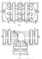
- the digital filter arrangement according to FIG. 1 contains a device 1 by means of which an input signal u is split into spectral partial signals V v in the form of complex low-pass signals. By indexing with the index ⁇ a running parameter (channel), e.g. B. V ⁇ k spe trales part signal for the v-th channel, respectively. These spectral partial signals V ⁇ are each processed in a device 2. Depending on the intended use, the processing in device 2 processes the input signal u in such a way that filtering and signal improvement or echo and feedback compensation or signal concealment or any combination thereof can be achieved . It proves to be advantageous that despite different uses the structure of the digital filter arrangement can be retained.
- the output signals W ⁇ of the device 2 are combined in a device 3 to form an output signal s such that the output signal s according to the purpose z. B. filtered
- the input signal u which, for. B. consists of a speech signal s and an additively superimposed interference signal n, using a filter bank (device 1) split into frequency bands.
- a filter bank (device 1) split into frequency bands.
- An advantageous embodiment of the filter bank is known, for example, from Signal Processing, Volume 2, 1980, pages 55-65. This consists of a so-called poly-phase network 11, which is connected to an FFT processor 12. The mode of operation of such a device 1 can be described by M equidistant channels with constant bandwidth.
- a complex-valued low-pass signal Vy is produced at each of the outputs in accordance with quadrature bandpass filtering with conversion to the low-pass position and with simultaneous clock reduction.
- This clock reduction or decimation of a sampling frequency for the input signal u can be described by a rotating switch 13 arranged on the input side of the digital filter arrangement.
- an input memory can be provided for this.
- the digital filter arrangement can advantageously be operated with the theoretically lowest possible clock frequency and the computational effort can be reduced.
- the polyphase network 11 contains a number of sub-filters 14, the coefficients of which can be set, in accordance with the number M of the spectral partial signals Vy.
- the choice of the coefficients of the partial filters 14 can be described by the choice of the coefficients of a recursive or non-recursive prototype low-pass filter with its impulse response h TP . By the The frequency response of the prototype low-pass filter determines the spectral resolution.
- the output signals v of the partial filters 14 ⁇ ( ⁇ -filtered component signals v) of Polyphasennetzwerkes 11 can be described by the following equation
- the clock can be reduced by a factor r ⁇ M.
- the filtered partial signals v ⁇ are converted into complex-valued low-pass signals V ⁇ in the FFT processor 12 with the aid of the discrete Fourier transform calculation method.
- the discrete Fourier transformation does not have the meaning of a spectral transformation but rather a complex calculation rule for the formation of linear combinations of the time signals v i .
- Each of the complex-value low-pass signals V ⁇ can be subjected to adaptive, complex-value filtering for noise reduction.
- this filtering can also be carried out as level control.
- the level control preferably an adaptive level control, the real and imaginary parts can be controlled independently of one another.
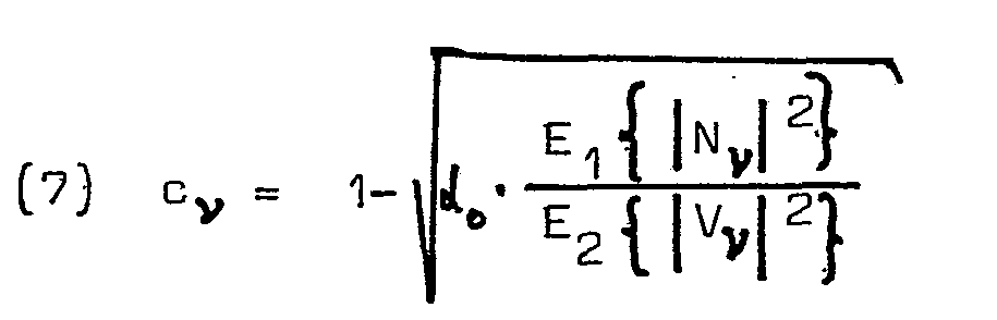
- devices 21 are provided in device 2, with which, for example, a level factor c ⁇ common for each channel can be selected. The following equations then apply to the complex-value output signals W v of the devices 21 with a level factor c ⁇ or
- the short-term powers of the interference signals N ⁇ are calculated in the speech pauses, the time constants of the averaging being controlled by a speech pause detector.
- the constants ⁇ i or the window lengths can be selected, for example, under the condition of stationary disturbance, that the short-term power of the complex time signals W ⁇ after level control with the short-term powers of the undisturbed signal components S ⁇ agree.
- the resultant, complex-value signals W ⁇ are used to convert the output signal s by an inverse operation in an FFT processor 31 which is connected to a polyphase network 34 and by inverse polyphase filtering.
- an FFT processor 31 which is connected to a polyphase network 34 and by inverse polyphase filtering.
- the clock frequency of the samples is increased again to the original clock frequency for the input signal u.
- This clock increase at the output of the digital filter arrangement is described in FIG. 1 with a switch 33.
- the equations below apply to the inverse operations
- spectral partial signals V v can be separated into real and imaginary parts, the use of adaptive level control for real and imaginary parts, for example, is possible.
- Recursive and non-recursive prototype filters can be used for partial filters 14 and 32, respectively. With the help of A highly effective noise reduction with minimal distortion of the speech signal with a small number of channels M can be achieved according to the inventive method.
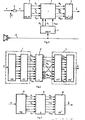
- FIG. 2 shows a further embodiment for the digital filter in the event that a reference signal r, which is correlated with the disturbance n, is available.
- the input signal in this case the reference signal r, is split into spectral partial signals R v by means of the decimating technique.
- adaptive level control in each channel e.g. B. the common level factor c ⁇ can be determined according to the following equation
- 2 is determined from the quotient of the short-term powers of the interference signal N ⁇ (see equation (8)) and the reference signal R v in the speech pauses.
- FIG. 3 shows the use of the digital filter arrangement according to the invention for echo and feedback compensation.
- a microphone 5 an echo voice signal g ⁇ is superimposed on the voice signal s.
- An estimate signal s ⁇ is formed from the microphone signal (s + g) in the digital filter arrangement by the method steps: splitting the microphone signal into spectral partial signals by means of a decimating technique, processing this spectral part signals were applied, for example, by real-value, adaptive level control and the composition of these spectral partial signals by means of interpolating technology.
- a reference signal is used to derive the adaptive, relative value level factors, which in the present case is identical to a loudspeaker signal g.
- the mean quadratic transfer function can be measured according to the following equation by measuring the short-term powers of the spectral partial signals G ⁇ ⁇ and G v be determined. It is also possible to feed a test signal, which is, for example, white noise or a multi-frequency signal, for the measurement instead of the loudspeaker signal g before the start of the conversation.
- FIG. 4 shows the use of the digital filter arrangement according to the invention for signal concealment.
- devices e.g. DT-PS 12 73 002
- the voice frequency band is divided into several subbands of the same width and the subbands are interchanged.
- the band switching method can be used.
- an exchanger selects n from 2n modulators, each of which is assigned a fixed carrier frequency.
- signal disguise can be achieved by interchanging and / or inversion of frequency bands.
- the complex-value low-pass signals V ⁇ of the device 1 are first z. B. for noise reduction, as described with reference to Figure 1, the device 2 supplied.
- the complex time signals W ⁇ at the outputs of the device 2 are staggered in terms of their frequences.
- the yth band is inverted by interchanging the signals W ⁇ and W M- ⁇ or by reversing the sign of the imaginary parts of Wy and W M- ⁇ .
- a band swapping can be achieved by swapping W ⁇ with W and W M- ⁇ with W M- ⁇ for ⁇ ⁇ u.
- FIG. 4 shows the swapping for the complex-valued time signals W 1 with W 2 and the inversion of W 3 .
- the noise reduction can be carried out either before or after the signal concealment.
- FIG. 5 shows a further exemplary embodiment for signal concealment by means of the digital filter arrangement.
- the processing and assignment of the complex time signals Wy can be represented by vectorial mapping. This makes it possible to combine the process steps FFT (Fast Fourier Transformation), processing, assignment and inverse FFT into a matrix multiplication.
- FFT Fast Fourier Transformation
- a vector v whose components are the filtered partial signals v 0 , v 1 ... v M-1 is obtained by multiplying by a matrix 6 immediate b a r to the vector w with the components w 0, w 1, ... w M-1 according to the following equation pictured.
- signal processing z. B. filtering, signal improvement (with or without reference), echo or feedback compensation can be implemented simultaneously or in any combination by means of a digital filter arrangement according to FIGS. 3 and 4.
- g and r can either be added first and then fed to the device 3, or a plurality of separate devices 4 can be provided.
Landscapes
- Engineering & Computer Science (AREA)
- Signal Processing (AREA)
- Computer Networks & Wireless Communication (AREA)
- Physics & Mathematics (AREA)
- Health & Medical Sciences (AREA)
- Mathematical Physics (AREA)
- Computational Linguistics (AREA)
- Quality & Reliability (AREA)
- Computer Hardware Design (AREA)
- Audiology, Speech & Language Pathology (AREA)
- Human Computer Interaction (AREA)
- Acoustics & Sound (AREA)
- Multimedia (AREA)
- Noise Elimination (AREA)
- Cable Transmission Systems, Equalization Of Radio And Reduction Of Echo (AREA)
- Filters That Use Time-Delay Elements (AREA)
- Complex Calculations (AREA)
Abstract
Description
- Die Erfindung betrifft ein Verfahren zur Aufbereitung elektrischer Signale mit einer digitalen Filteranordnung, bei der ein oder mehrere Eingangssignale mittels einer dezimierenden Technik in spektrale Teilsignale aufgespaltet, diese spektralen Teilsignale verarbeitet und mittels einer interpolierenden Technik zum Ausgangssignal zusammengefügt werden.
- Die Art der Signalaufbereitung eines Signals ist im Sinne einer linearen Filterung oder einer Signalverbesserung oder einer Echo- bzw. Rückkopplungskompensation oder einer Signalverschleierung bzw. beliebiger Kombinationen davon, zu verstehen. Die Verarbeitung des Signals in einer digitalen Filteranordnung erfolgt zeitdiskret.
- Eine zeitdiskrete lineare Filterung ist beschreibbar im Zeitbereich durch die diskrete Faltung einer Filtereingangsimpulsfolge u(k) mit einer Impulsantwort h(k) des Filters, d h. durch die Gleichung

 ·/fF).
- Eine Signal verbesserung ist erforderlich, wenn dem Signal eine additive Störung überlagert ist. Diese Störung kann durch akustische Hintergrundgeräusche oder durch elektrische Störungen im Übertragungskanal hervorgerufen werden. Unter der Voraussetzung einer schwachen Stationarität der Störung können mittels einer fortlaufend ausgeführten Parameter-Identifikation die stationären Intervalle d. h. die Sprachpausen und damit die Parameter der Störung erkannt werden. Mit den so gewonnenen Parametern werden die Filterkoeffizienten eines Optimalfilters berechnet (US-PS 40 25 721), das den verbleibenden Restfehler nach gewissen Kriterien minimiert. Ein weiteres Zeitbereichsfilterverfahren ist aus der DT-AS 27 49 132 bekannt, bei dem zur Signalverbesserung ein adaptives, digitales Transversalfilter verwendet wird, wobei die Filterkoeffizienten nach einem Gradientenalgorithmus eingestellt werden und wobei das so gebildete Schätzsignal eine möglichst gute Reproduktion des Originalsignals darstellen soll. Ein weiteres Verfahren zur Signalverbesserung ist die sogenannte spektrale Subtraktion. Dabei wird mit Hilfe der Spektraltransformation FFT (Fast Fourier Transform)das Kurzzeitspektrum des gestörten Signals nach Betrag (bzw. Leistung) und Phase ermittelt. Das Betrags-(bzw. Leistungs-) Spektrum wird im wesentlichen durch Subtraktion eines geschätzten Betrags- (Leistungs-) Spektrums der Störung korrigiert. Anschließend wird die Phase des gestörten Signals hinzugefügt und eine inverse FFT ausgeführt. Dieses bekannte Verfahren ist beispielsweise aus einer Abhandlung in den IEEE-Transactions, Bd.ASSP-26, 1978., Seiten 471 - 472 bzw. Bd. ASSP-27, Seite 113 - 120 entnehmbar.
- Das Problem der Echo- und Rückkoppiungs- kompensation tritt beispielsweise bei der Fernsprechübertragung auf. Durch Reflexionen an Gabelschaltungen entstehen störende Echos die mit Hilfe eines adaptiven Filters zu kompensieren sind. Im Zusammenhang mit einem sogenannten Lautfernsprecher kann zur Unterdrückung der Rückkopplung ein adaptives Filter eingesetzt werden.
- Zur Signal verschleierung kann das Signalspektrum in mehrere Frequenzbänder aufgespaltet, diese untereinander vertauscht und/oder frequenzmäßig in Kehrlage gebracht werden. Dadurch kann ein Übertragungskanal gegen unbefugtes Abhören gesichert werden (z.B. DT-AS 1 273 002).
- Der Erfindung liegt die Aufgabe zugrunde, eine digitale Filteranordnung mit einem geringen Aufwand an Mitteln zu realisieren, bei der die verschiedenen Arten der Signalaufbereitung in beliebiger Kombination gewählt werden können.
- Diese Aufgabe wird durch die im Anspruch 1 gekennzeichneten Merkmale gelöst.
- Gegenüber den bekannten Verfahren ist damit eine wesentliche Verbesserung der Funktionsweise und eine erhebliche Reduzierung für den Aufwand an Mitteln erreichbar.
- Im weiteren wird die Erfindung anhand einer ausführlichen Beschreibung eines Ausführungsbeispiels unter Bezugnahme auf beiliegende Zeichnung veranschaulicht.
- Es zeigt:
- Figur 1 das Blockschaltbild der digitalen Filteranordnung gemäß der Erfindung,
- Figur 2 ein weiteres Blockschaltbild der digitalen Filteranordnung mit einem zusätzlichen Referenzsignal,
- Figur 3 das Prinzipschaltbild für die Anwendung der digitalen Filteranordnung zur Echo- und Rückkopplungskompensation bei einem Lautfernsprecher,
- Figur 4 eine Ausführungsform der erfindungsgemäßen Filteranordnung bei Verwendung zur Sprachverschleierung,
- Figur 5 ein weiteres Ausführungsbeispiel für die digitale Filteranordnung nach Figur 4.
- Die digitale Filteranordnung nach Figur 1 enthält eine Einrichtung 1 mittels der ein Eingangssignal u in spektrale Teilsignale Vv in der Form komplexwertiger Tiefpaßsignale aufgespaltet wird. Durch die Indizierung mit dem Index ν wird ein Laufparameter (Kanal), z. B. Vν spektrales Teilsignal für den v-ten Kanal, bezeichnet. Diese spektralen Teilsignale Vν werden jeweils in einer Einrichtung 2 verarbeitet Durch die Verarbeitung in der Einrichtung 2 wird je nach Verwendungszweck das Eingangssignal u so aufbereitet, daß eine Filterung und Signalverbesserung oder eine Echo- und Rückkopplungskompensation oder eine Signalverschleierung bzw. beliebige Kombinationen davon erreichbar sind. Dabei erweist es sich als vorteilhaft, daß trotz unterschiedlichen Verwendungszwecks die Struktur der digitalen Filteranordnung beibehalten werden kann. Die Ausgangssignale Wν der Einrichtung 2 werden in einer Einrichtung 3 so zu einem Ausgangssignal s zusammengefügt, daß das Ausgangssignal s gemäß dem Verwendungszweck z. B. gefiltert vorliegt
- Zur Filterung und Signalverbesserung des Eingangssignals u wird das Eingangssignal u, welches z. B. aus einem Sprachsignal s und einem additiv überlagerten Störsignal n besteht, mit Hilfe einer Filterbank (Einrichtung 1) in Frequenzbänder aufgespaltet. Eine vorteilhafte Ausführung der Filterbank ist beispielsweise aus Signal Processing, Band 2, 1980, Seiten 55 - 65 bekannt. Diese besteht aus einem sogenannten Polyphasennetzwerk 11, welches mit einem FFT-Prozessor 12 verbunden ist. Die Wirkungsweise einer solchen Einrichtung 1 ist beschreibbar durch M äquidistante Kanäle mit konstanter Bandbreite. Am Ausgang der Einrichtung 1 entsteht an jedem der Ausgänge ein komplexwertiges Tiefpaßsignal Vy gemäß einer Quadratur-Bandpaßfilterung mit Umsetzung in die Tiefpaßlage und mit gleichzeitiger Taktreduktion. Diese Taktreduktion bzw. Dezimierung einer Abtastfrequenz für das Eingangssignal u ist beschreibbar durch einen eingangsseitig der digitalen Filteranordnung angeordneten und rotierenden Schalter 13. Bei der Realisierung kann dafür ein Eingabespeicher vorgesehen sein. Dadurch kann in vorteilhafter Weise die digitale Filteranordnung mit der theoretisch kleinstmöglichen Taktfrequenz betrieben und der Rechenaufwand verringert werden.
- Das Polyphasennetzwerk 11 enthält entsprechend der Anzahl M der spektralen Teilsignale Vy eine Reihe von Teilfiltern 14, deren Koeffizienten einstellbar sind. Die Wahl der Koeffizienten der Teilfilter 14 ist beschreibbar durch die Wahl der Koeffizienten eines rekursiven oder nichtrekursiven Prototyp-Tiefpasses mit dessen Impulsantwort hTP. Durch den Frequenzgang des Prototyp-Tiefpasses wird die spektrale Auflösung bestimmt. Die Ausgangssignale vµ der Teilfilter 14 (gefilterte Teilsignale vµ) des Polyphasennetzwerkes 11 sind beschreibbar durch folgende Gleichung

- Wie aus Gleichung (3) ersichtlich, erfolgt die Berechnung zu den diskreten Zeitpunkten k = s·M (S =0, 1, 2, ...) entsprechend einer Taktreduktion um den Faktor M (Dezimierung). Im allgemeinen kann eine Taktreduktion um einen Faktor r ≠ M erfolgen.
- Die gefilterten Teilsignale vµ werden mit Hilfe des Rechenverfahrens der diskreten Fourier Transformation im FFT-Prozessor 12 in komplexwertige TiefpaBsignale Vν übergeführt. Für das komplexwertige TiefpaBsignal Vν gilt folgende

- Dabei besitzt die diskrete Fourier Transformation nicht die Bedeutung einer Spektraltransformation sondern einer komplexwertigen Rechenvorschrift zur Bildung linearer Kombinationen der Zeitsignale vi. Durch Einsetzen von Gleichung (3) in Gleichung (4a) erhält man nach einer Umformung unter Berücksichtigung der Periodizitäten der komplexen Gewichtungsfaktoren

- Es handelt sich um komplexwertige TiefpaB-Signale, die durch komplexe Modulation (Spektralverschiebung um

- Jedes der komplexwertigen Tiefpaßsignale Vν kann zur Geräuschreduktion einer adaptiven, komplexwertigen Filterung unterzogen werden. Im Sonderfall kann diese Filterung auch als Pegelsteuerung ausgeführt werden. Mittels der Pegelsteuerung, vorzugsweise einer adaptiven Pegelsteuerung, können jeweils Real- und Imaginärteil unabhängig voneinander geregelt werden. In der Einrichtung 2 sind dafür Einrichtungen 21 vorgesehen, mit denen beispielsweise ein pro Kanal gemeinsamer Pegelfaktor cν wählbar ist. Für die komplexwertigen Ausgangssignale Wv der Einrichtungen 21 gelten dann folgende Gleichungen


- Die spektralen Teilsignale Vν setzen sich jeweils aus Signalanteil Sv und Störanteil Nν gemäß


- Die Kurzzeitleistungen der Störsignale Nν werden in den Sprachpausen berechnet, wobei die Zeitkonstanten der Mittelwertbildung von einem Sprachpausendetektor gesteuert werden.
- Die Konstanten αi bzw. die Fensterlängen können unter der Voraussetzung stationärer Störung beispielsweise derart gewählt werden, daß in jedem Kanal die Kurzzeitleistungen der komplexwertigen Zeitsignale Wν nach erfolgter Pegelsteuerung mit den Kurzzeitleistungen der ungestörten Signalanteile Sν übereinstimmen.
- Aus den resultierenden, komplexwertigen Signalen Wν wird durch inverse Operation in einem FFT-Prozessor 31 der mit einem Polyphasennetzwerk 34 verbunden ist und durch inverse Polyphasenfilterung das Ausgangssignal s zusammengesetzt. Mit Hilfe der dabei verwendeten, sogenannten interpolierenden Technik wird die Taktfrequenz der Abtastwerte wieder auf die ursprüngliche Taktfrequenz für das Eingangssignal u erhöht. Diese Takterhöhung am Ausgang der digitalen Filteranordnung ist in Figur 1 mit einem Schalter 33 umschrieben. Für die inversen Operationen gelten im folgenden die Gleichungen


- Im Vergleich zum Verfahren der spektralen Subtraktion erfordert die beschriebene digitale Filteranordnung einen geringeren Rechen- bzw. Realisierungsaufwand. Die Nachbarkanäle sind bei geeigneter Wahl der Prototyp-Tiefpaß-Impulsantwort hTP gegenseitig entkoppelt. Durch kurze Blocklänge (z. B. M = 32) und minimalphasige Filterung sind geringe Verzögerungszeiten erreichbar.
- Da die spektralen Teilsignale Vv nach Real- und Imaginärteil trennbar sind, ist die Anwendung beispielsweise der adaptiven Pegelsteuerung getrennt für Real- und Imaginärteil möglich. Für die Teilfilter 14 bzw. 32 können rekursive und nichtrekursive Prototyp-Filter eingesetzt werden. Mit Hilfe des erfindungsgemäßen Verfahrens ist eine hochwirksame Geräuschreduktion mit minimaler Verzerrung des Sprachsignals bei geringer Kanalzahl M erreichbar.
- Figur 2 zeigt eine weitere Ausführungsform für das digitale Filter in dem Fall, daß ein Referenzsignal r, welches mit der Störung n korreliert ist, zur Verfügung steht. In einer weiteren Einrichtung 4 (Funktionsweise entsprechend der Einrichtung 1 nach Figur 1) wird das Eingangssignal, im vorliegenden Fall das Referenzsignal r, mittels der dezimierenden Technik in spektrale Teilsignale Rv aufgespaltet. Für den Sonderfall einer reellwertigen, adaptiven Pegelsteuerung in jedem Kanal kann z. B. der gemeinsame Pegelfaktor cν nach folgender Gleichung bestimmt werden
-

- In Figur 3 ist der Einsatz der erfindungsgemäBen digitalen Filteranordnung zur Echo- und Rückkopplungskompensation gezeigt. In einem Mikrofon 5 ist dem Sprachsignal s ein Echosprachsignal g̃ additiv überlagert. Aus dem Mikrofonsignal (s + g) wird in der digitalen Filteranordnung ein Schätzsignal s̃ gebildet, indem die Verfahrensschritte: Aufspalten des Mikrofonsignals in spektrale Teilsignale mittels einer dezimierenden Technik, Verarbeitung dieser spektralen Teilsignale beispielsweise durch reellwertige, adaptive Pegelsteuerung und Zusammensetzung dieser spektralen Teilsignale mittels interpolierender Technik angewendet wurden.
- In ähnlicher Weise wie in Figur 2 werden zur Ableitung der adaptiven, relwertigen Pegelfaktoren ein Referenzsignal verwendet, welches im vorliegenden Fall mit einem Lautsprecher- signal g identisch ist. In den Sprachpausen gilt Vy = G̃ν wegen s = 0 bzw. u = g̃. Durch Messung der Kurzzeitleistungen der spektralen Teilsignale G̃ν und Gv kann die mittlere quadratische Übertragungsfunktion gemäß folgender Gleichung

- Figur 4 zeigt die Verwendung der erfindungsgemäßen digitalen Filteranordnung zur Signalverschleierung. Zur verschleierten Übertragung von Sprachsignalen sind Einrichtungen (z. B. DT-PS 12 73 002) bekannt, bei denen das Sprachfrequenzband in mehrere gleichbreite Teilbänder aufgeteilt und die Teilbänder miteinander vertauscht werden. Zur Vertauschung der Teilbänder kann beispielsweise das Verfahren der Bandumschaltung verwendet werden. Dabei trifft ein Vertauscher die Auswahl von n aus 2n Modulatoren, denen jeweils eine feste Trägerfrequenz zugeordnet ist.
- Mit der in Figur 4 gezeigten digitalen Filteranordnung läBt sich eine Signalverschleierung durch Vertauschen und/oder Inversion von Frequenzbändern erreichen.
- Die komplexwertigen TiefpaBsignale Vν der Einrichtung 1 werden zunächst z. B. zur Geräuschreduktion, wie anhand Figur 1 beschrieben, der Einrichtung 2 zugeführt. Die komplexwertigen Zeitsignale Wν an den Ausgängen der Einrichtung 2 liegen hinsichtlich ihrer Frequezen gestaffelt vor. Die Inversion des y-ten Bandes erfolgt durch Vertauschen der Signale Wν und WM-ν oder durch Vorzeichenumkehr der Imaginärteile von Wy und WM-ν. Eine Bandvertauschung kann durch Vertauschen von Wν mit W und WM-ν mit WM-µ für ν≠u erreicht werden In Figur 4 ist die Vertauschung für die komplexwertigen Zeitsignale W1 mit W2 und die Inversion von W3 dargestellt. Schließlich sei noch erwähnt, daß die Geräuschreduktion wahlweise vor oder nach der Signalverschleierung vorgenommen werden kann.
- Figur 5 zeigt ein weiteres Ausführungsbeispiel zur Signalverschleierung mittels der digitalen Filteranordnung. Die Verarbeitung und Zuordnung der komplexwertigen Zeitsignale Wy läßt sich durch vektorielle Abbildung darstellen. Dadurch ist es möglich die Verfahrensschritte FFT ( Fast Fourier Transformation), Verarbeitung, Zuordnung und inverse FFT zu einer Matrixmultiplikation zusammenzufassen.Ein Vektor v dessen Komponenten die gefilterten Teilsignale v0, v1...vM-1 sind, wird durch Multiplikation mit einer Matrix 6 unmittel- bar auf den Vektor w mit den Komponenten w0, w 1, ... wM-1, entsprechend folgender Gleichung

- Die verschiedenen Arten der Signalaufbereitung z. B. Filterung, Signalverbesserung (mit oder ohne Referenz), Echo- bzw. Rückkopplungskompensation lassen sich gleichzeitig oder in beliebiger Kombination mittels einer digitalen Filteranordnung gemäß Figur 3 und 4 realisieren.
- Wird beispielsweise entsprechend zur Figur 3-eine Rückkopplungskompensation und eine Signalverbesserung gleichzeitig angestrebt, so können g und r entweder zunächst addiert und dann der Einrichtung 3 zugeführt werden oder aber es können mehrere voneinander getrennte Einrichtungen 4 vorgesehen sein.
Claims (6)
Applications Claiming Priority (2)
| Application Number | Priority Date | Filing Date | Title |
|---|---|---|---|
| DE3118473A DE3118473C2 (de) | 1981-05-09 | 1981-05-09 | Verfahren zur Aufbereitung elektrischer Signale mit einer digitalen Filteranordnung |
| DE3118473 | 1981-05-09 |
Publications (3)
| Publication Number | Publication Date |
|---|---|
| EP0065210A2 true EP0065210A2 (de) | 1982-11-24 |
| EP0065210A3 EP0065210A3 (en) | 1984-09-05 |
| EP0065210B1 EP0065210B1 (de) | 1987-01-28 |
Family
ID=6131908
Family Applications (1)
| Application Number | Title | Priority Date | Filing Date |
|---|---|---|---|
| EP82103859A Expired EP0065210B1 (de) | 1981-05-09 | 1982-05-05 | Verfahren zur Aufbereitung elektrischer Signale mit einer digitalen Filteranordnung |
Country Status (5)
| Country | Link |
|---|---|
| US (1) | US4623980A (de) |
| EP (1) | EP0065210B1 (de) |
| JP (1) | JPS5830219A (de) |
| CA (1) | CA1201178A (de) |
| DE (2) | DE3118473C2 (de) |
Cited By (9)
| Publication number | Priority date | Publication date | Assignee | Title |
|---|---|---|---|---|
| EP0200239A3 (en) * | 1985-03-23 | 1989-01-11 | Philips Patentverwaltung Gmbh | Digital analysis-synthesis filter bank with maximum sampling-rate reduction |
| EP0227614A3 (de) * | 1985-12-24 | 1989-06-14 | SELENIA INDUSTRIE ELETTRONICHE ASSOCIATE S.p.A. | Signalverarbeitungsvorrichtung für Radar mit synthetischer Apertur, insbesondere geeignet für Parallelberechnung |
| EP0293866A3 (de) * | 1987-06-02 | 1990-05-02 | Fujitsu Limited | Geheimspracheneinrichtung |
| EP0332890A3 (de) * | 1988-03-14 | 1991-04-10 | International Business Machines Corporation | Rauschunterdrückung bei einem verrauschten Sprachsignal |
| WO1991014310A1 (en) * | 1990-03-08 | 1991-09-19 | British Aerospace Public Limited Company | Apparatus for and method of digital signal processing |
| EP0443547A3 (en) * | 1990-02-21 | 1991-12-04 | Fujitsu Limited | Sub-band acoustic echo canceller |
| FR2680924A1 (fr) * | 1991-09-03 | 1993-03-05 | France Telecom | Procede de filtrage adapte d'un signal transforme en sous-bandes, et dispositif de filtrage correspondant. |
| EP0501690A3 (en) * | 1991-02-28 | 1993-07-21 | British Aerospace Public Limited Company | Apparatus for and method of digital signal processing |
| FR2739736A1 (fr) * | 1995-10-05 | 1997-04-11 | Laroche Jean | Procede de reduction des pre-echos ou post-echos affectant des enregistrements audio |
Families Citing this family (39)
| Publication number | Priority date | Publication date | Assignee | Title |
|---|---|---|---|---|
| DE3230391A1 (de) * | 1982-08-14 | 1984-02-16 | Philips Kommunikations Industrie AG, 8500 Nürnberg | Verfahren zur signalverbesserung von gestoerten sprachsignalen |
| EP0131641B1 (de) * | 1983-07-14 | 1988-10-12 | ANT Nachrichtentechnik GmbH | Verfahren zur Anpassung von zwei Systemen mit unterschiedlicher Abtastrate |
| FR2577084B1 (fr) * | 1985-02-01 | 1987-03-20 | Trt Telecom Radio Electr | Systeme de bancs de filtres d'analyse et de synthese d'un signal |
| US4698769A (en) * | 1985-02-04 | 1987-10-06 | American Telephone And Telegraph Company | Supervisory audio tone detection in a radio channel |
| US4868773A (en) * | 1985-03-15 | 1989-09-19 | Purdue Research Foundation | Digital filtering by threshold decomposition |
| DE3510352C1 (de) * | 1985-03-22 | 1986-09-11 | ANT Nachrichtentechnik GmbH, 7150 Backnang | Gegensprech-Übertragungseinrichtung |
| US4709344A (en) * | 1985-10-02 | 1987-11-24 | Motorola, Inc. | Programmable multifrequency digital tone receiver |
| GB2181318B (en) * | 1985-10-04 | 1989-12-28 | Sony Corp | Two-dimensional finite impulse response filters |
| US4825396A (en) * | 1986-02-14 | 1989-04-25 | Siemens Aktiengesellschaft | Digital circuit for sampling rate variation and signal filtering and method for constructing the circuit |
| JPS6345933A (ja) * | 1986-04-15 | 1988-02-26 | Nec Corp | 秘話装置 |
| JPS63196450A (ja) * | 1987-02-04 | 1988-08-15 | Kiyuwatsuto Kk | 可動トレイ型ソ−タ |
| JP2870756B2 (ja) * | 1988-04-20 | 1999-03-17 | 株式会社リコー | 空間フィルタ画像処理装置 |
| DE3834188A1 (de) * | 1988-10-07 | 1990-04-12 | Thomson Brandt Gmbh | Filter |
| JP2774296B2 (ja) * | 1989-01-20 | 1998-07-09 | キヤノン株式会社 | 情報処理方法及びその装置 |
| US5029184A (en) * | 1990-01-24 | 1991-07-02 | Harris Corporation | Low probability of intercept communication system |
| DE4021787A1 (de) * | 1990-07-09 | 1992-01-16 | Telefunken Electronic Gmbh | Elektro-akustisches system |
| US5305307A (en) * | 1991-01-04 | 1994-04-19 | Picturetel Corporation | Adaptive acoustic echo canceller having means for reducing or eliminating echo in a plurality of signal bandwidths |
| US5282222A (en) * | 1992-03-31 | 1994-01-25 | Michel Fattouche | Method and apparatus for multiple access between transceivers in wireless communications using OFDM spread spectrum |
| USRE37802E1 (en) | 1992-03-31 | 2002-07-23 | Wi-Lan Inc. | Multicode direct sequence spread spectrum |
| WO1994001933A1 (en) * | 1992-07-07 | 1994-01-20 | Lake Dsp Pty. Limited | Digital filter having high accuracy and efficiency |
| US5606575A (en) * | 1993-10-29 | 1997-02-25 | Airnet Communications Corporation | FFT-based channelizer and combiner employing residue-adder-implemented phase advance |
| US5535240A (en) * | 1993-10-29 | 1996-07-09 | Airnet Communications Corporation | Transceiver apparatus employing wideband FFT channelizer and inverse FFT combiner for multichannel communication network |
| US6192068B1 (en) | 1996-10-03 | 2001-02-20 | Wi-Lan Inc. | Multicode spread spectrum communications system |
| US5926455A (en) * | 1996-12-19 | 1999-07-20 | Lucent Technologies Inc. | Recursive filters for polyphase structures |
| US6130943A (en) * | 1996-12-23 | 2000-10-10 | Mci Communications Corporation | Method and apparatus for suppressing echo in telephony |
| US5933421A (en) * | 1997-02-06 | 1999-08-03 | At&T Wireless Services Inc. | Method for frequency division duplex communications |
| RU2123758C1 (ru) * | 1997-07-08 | 1998-12-20 | Камчатский гидрофизический институт | Цифровой фильтр |
| SG71035A1 (en) * | 1997-08-01 | 2000-03-21 | Bitwave Pte Ltd | Acoustic echo canceller |
| US6026123A (en) * | 1997-08-02 | 2000-02-15 | Williams; Thomas H. | Digital transmission system with high immunity to dynamic linear distortion |
| WO1999049574A1 (en) * | 1998-03-25 | 1999-09-30 | Lake Technology Limited | Audio signal processing method and apparatus |
| US6604071B1 (en) | 1999-02-09 | 2003-08-05 | At&T Corp. | Speech enhancement with gain limitations based on speech activity |
| GB2348350B (en) * | 1999-03-26 | 2004-02-18 | Mitel Corp | Echo cancelling/suppression for handsets |
| RU2182724C2 (ru) * | 2000-02-09 | 2002-05-20 | Самарский государственный технический университет | Устройство для выполнения преобразования фурье |
| RU2182358C2 (ru) * | 2000-02-28 | 2002-05-10 | Самарский государственный технический университет | Устройство для выполнения преобразования фурье |
| US6718038B1 (en) * | 2000-07-27 | 2004-04-06 | The United States Of America As Represented By The National Security Agency | Cryptographic method using modified fractional fourier transform kernel |
| WO2002086755A1 (en) * | 2001-04-24 | 2002-10-31 | California Institute Of Technology | Method and apparatus for parallel signal processing |
| FR2834563B1 (fr) * | 2002-01-08 | 2004-04-02 | Thales Sa | Procede de suppression de signaux radioelectriques pulses et dispositif de mise en oeuvre du procede |
| KR100454886B1 (ko) * | 2002-02-01 | 2004-11-06 | 한국과학기술원 | 독립 성분 분석을 이용한 여파기 적응 알고리즘의 필터뱅크 접근 방법 |
| DE10352537A1 (de) * | 2003-11-11 | 2005-06-09 | Siemens Ag | Verfahren und Filterbank zur spektralen Modifikation eines digitalen Signals |
Family Cites Families (17)
| Publication number | Priority date | Publication date | Assignee | Title |
|---|---|---|---|---|
| DE1273002B (de) * | 1963-09-11 | 1968-07-18 | Siemens Ag | Einrichtung zur verschluesselten UEbertragung von Sprachsignalen durch Vertauschung von Teilbaendern |
| CH580893A5 (de) | 1973-07-02 | 1976-10-15 | Gretag Ag | |
| DE2426451B2 (de) * | 1974-05-31 | 1976-10-28 | Siemens AG, 1000 Berlin und 8000 München | Schaltungsanordnung fuer einrichtungen zur teilbandvertauschung |
| FR2315809A1 (fr) | 1975-06-24 | 1977-01-21 | Trt Telecom Radio Electr | Systeme de transmission des signaux auxiliaires d'un groupe de voies telephoniques d'un multiplex a repartition en frequence |
| JPS5227239A (en) * | 1975-08-26 | 1977-03-01 | Toshiba Corp | Filter |
| JPS5234647A (en) * | 1975-09-12 | 1977-03-16 | Hitachi Ltd | Frequency sampling filter |
| US4020332A (en) | 1975-09-24 | 1977-04-26 | Bell Telephone Laboratories, Incorporated | Interpolation-decimation circuit for increasing or decreasing digital sampling frequency |
| US4025721A (en) | 1976-05-04 | 1977-05-24 | Biocommunications Research Corporation | Method of and means for adaptively filtering near-stationary noise from speech |
| US4052559A (en) | 1976-12-20 | 1977-10-04 | Rockwell International Corporation | Noise filtering device |
| FR2412987A1 (fr) | 1977-12-23 | 1979-07-20 | Ibm France | Procede de compression de donnees relatives au signal vocal et dispositif mettant en oeuvre ledit procede |
| NL7902053A (nl) | 1979-03-15 | 1980-09-17 | Philips Nv | Echocompensator voor homochrone data overdrachtssyste- men. |
| US4316282A (en) | 1979-11-23 | 1982-02-16 | Rca Corporation | Multichannel frequency translation of sampled waveforms by decimation and interpolation |
| US4302631A (en) | 1979-11-28 | 1981-11-24 | International Telephone And Telegraph Corporation | Decimator apparatus for decreasing the word rate of a digital signal of the type employed in digital telephone systems |
| US4281318A (en) | 1980-05-30 | 1981-07-28 | Bell Telephone Laboratories, Incorporated | Digital-to-digital code converter |
| DE3032397A1 (de) * | 1980-08-28 | 1982-03-11 | Battelle-Institut E.V., 6000 Frankfurt | Schaltungsanordnung fuer ein einstellbares elektrisches filter |
| US4389538A (en) | 1981-01-12 | 1983-06-21 | Rockwell International Corporation | Multiplexer for single-octave data processor |
| US4393456A (en) | 1981-03-19 | 1983-07-12 | Bell Telephone Laboratories, Incorporated | Digital filter bank |
-
1981
- 1981-05-09 DE DE3118473A patent/DE3118473C2/de not_active Expired
-
1982
- 1982-05-05 EP EP82103859A patent/EP0065210B1/de not_active Expired
- 1982-05-05 DE DE8282103859T patent/DE3275340D1/de not_active Expired
- 1982-05-07 CA CA000402552A patent/CA1201178A/en not_active Expired
- 1982-05-07 JP JP57075535A patent/JPS5830219A/ja active Pending
-
1985
- 1985-03-08 US US06/709,358 patent/US4623980A/en not_active Expired - Fee Related
Cited By (13)
| Publication number | Priority date | Publication date | Assignee | Title |
|---|---|---|---|---|
| EP0200239A3 (en) * | 1985-03-23 | 1989-01-11 | Philips Patentverwaltung Gmbh | Digital analysis-synthesis filter bank with maximum sampling-rate reduction |
| EP0227614A3 (de) * | 1985-12-24 | 1989-06-14 | SELENIA INDUSTRIE ELETTRONICHE ASSOCIATE S.p.A. | Signalverarbeitungsvorrichtung für Radar mit synthetischer Apertur, insbesondere geeignet für Parallelberechnung |
| EP0293866A3 (de) * | 1987-06-02 | 1990-05-02 | Fujitsu Limited | Geheimspracheneinrichtung |
| EP0332890A3 (de) * | 1988-03-14 | 1991-04-10 | International Business Machines Corporation | Rauschunterdrückung bei einem verrauschten Sprachsignal |
| US5136577A (en) * | 1990-02-21 | 1992-08-04 | Fujitsu Limited | Sub-band acoustic echo canceller |
| EP0443547A3 (en) * | 1990-02-21 | 1991-12-04 | Fujitsu Limited | Sub-band acoustic echo canceller |
| WO1991014310A1 (en) * | 1990-03-08 | 1991-09-19 | British Aerospace Public Limited Company | Apparatus for and method of digital signal processing |
| EP0501690A3 (en) * | 1991-02-28 | 1993-07-21 | British Aerospace Public Limited Company | Apparatus for and method of digital signal processing |
| FR2680924A1 (fr) * | 1991-09-03 | 1993-03-05 | France Telecom | Procede de filtrage adapte d'un signal transforme en sous-bandes, et dispositif de filtrage correspondant. |
| EP0531242A1 (de) * | 1991-09-03 | 1993-03-10 | France Telecom | Adaptives Filterverfahren eines in Teilbändern transformierten Signals und entsprechende Filteranordnung |
| FR2739736A1 (fr) * | 1995-10-05 | 1997-04-11 | Laroche Jean | Procede de reduction des pre-echos ou post-echos affectant des enregistrements audio |
| EP0767462A3 (de) * | 1995-10-05 | 1997-08-06 | France Telecom | Verfahren zur Reduzierung von Audioaufzeichnung beeinflussenden Vor- und Nachechos |
| US5717768A (en) * | 1995-10-05 | 1998-02-10 | France Telecom | Process for reducing the pre-echoes or post-echoes affecting audio recordings |
Also Published As
| Publication number | Publication date |
|---|---|
| DE3118473C2 (de) | 1987-02-05 |
| EP0065210A3 (en) | 1984-09-05 |
| US4623980A (en) | 1986-11-18 |
| DE3275340D1 (en) | 1987-03-05 |
| JPS5830219A (ja) | 1983-02-22 |
| DE3118473A1 (de) | 1982-11-25 |
| EP0065210B1 (de) | 1987-01-28 |
| CA1201178A (en) | 1986-02-25 |
Similar Documents
| Publication | Publication Date | Title |
|---|---|---|
| EP0065210B1 (de) | Verfahren zur Aufbereitung elektrischer Signale mit einer digitalen Filteranordnung | |
| DE3510660C2 (de) | ||
| EP0200239B1 (de) | Digitale Polyphasen-Filterbank mit maximaler Taktreduktion | |
| EP1525576B1 (de) | Vorrichtung und verfahren zum erzeugen einer komplexen spektraldarstellung eines zeitdiskreten signals | |
| DE3405010A1 (de) | Vorrichtung zur erzeugung eines verzoegerungsschaetzwertes fuer eine echoausloescheinrichtung | |
| DE19956088A1 (de) | Einseiten-Unterband-Filter | |
| DE2616660A1 (de) | Arithmetische einheit | |
| EP0577653B1 (de) | Verfahren zum ermitteln der übertragungseigenschaften einer elektrischen leitung | |
| EP0957471B1 (de) | Messverfahren zur gehörrichtigen Qualitätsbewertung von Audiosignalen | |
| EP1239455A2 (de) | Verfahren und Anordnung zur Durchführung einer an die Übertragungsfunktion menschilcher Sinnesorgane angepassten Fourier Transformation sowie darauf basierende Vorrichtungen zur Geräuschreduktion und Spracherkennung | |
| DE3852921T2 (de) | Digitale Filteranordnung und Radar mit solch einer Anordnung. | |
| DE4427124A1 (de) | Anordnung zur Kommunikation mit einem Teilnehmer | |
| DE3230391C2 (de) | ||
| EP0075311B1 (de) | Anordnung zur Übertragung von Sprache nach dem Kanalvocoderprinzip | |
| EP0855806B1 (de) | Echosperre für ein Spracheingabe Dialogsystem | |
| DE19729521B4 (de) | Verfahren und Vorrichtung zur Störgeräusch- und Echounterdrückung | |
| DE3883414T2 (de) | Digitales Signalverarbeitungssystem mit einer Filterbank. | |
| AT371639B (de) | Verfahren zur aufbereitung elektrischer signale mit einer digitalen filteranordnung | |
| DE102007018585A1 (de) | Vorrichtung und Verfahren zur Ermittlung und Kompensation von Störsignalen in einem Nachrichtenübertragungssystem | |
| DE69622222T2 (de) | Nicht-beeinflussende Bestimmung der Übertragungsqualität auf Telephonleitungen | |
| DE19954088C2 (de) | Verfahren zur Filterung einer digitalen Signalfolge | |
| DE3732047C2 (de) | ||
| DE19947682A1 (de) | Nullverzögerungs-Struktur zur Subband-Echokompensation, Echokompensation und Verfahren zur Echokompensation | |
| DE69602838T2 (de) | Adaptive teilbandfiltrierung | |
| DE19601405B4 (de) | Verfahren und Vorrichtung zur Systemidentifikation und Echokompensation in Übertragungssystemen |
Legal Events
| Date | Code | Title | Description |
|---|---|---|---|
| PUAI | Public reference made under article 153(3) epc to a published international application that has entered the european phase |
Free format text: ORIGINAL CODE: 0009012 |
|
| AK | Designated contracting states |
Designated state(s): CH DE FR GB LI NL SE |
|
| 17P | Request for examination filed |
Effective date: 19821018 |
|
| PUAL | Search report despatched |
Free format text: ORIGINAL CODE: 0009013 |
|
| AK | Designated contracting states |
Designated state(s): CH DE FR GB LI NL SE |
|
| 17Q | First examination report despatched |
Effective date: 19860220 |
|
| GRAA | (expected) grant |
Free format text: ORIGINAL CODE: 0009210 |
|
| AK | Designated contracting states |
Kind code of ref document: B1 Designated state(s): CH DE FR GB LI NL SE |
|
| REF | Corresponds to: |
Ref document number: 3275340 Country of ref document: DE Date of ref document: 19870305 |
|
| PGFP | Annual fee paid to national office [announced via postgrant information from national office to epo] |
Ref country code: NL Payment date: 19870531 Year of fee payment: 6 |
|
| ET | Fr: translation filed | ||
| PLBE | No opposition filed within time limit |
Free format text: ORIGINAL CODE: 0009261 |
|
| STAA | Information on the status of an ep patent application or granted ep patent |
Free format text: STATUS: NO OPPOSITION FILED WITHIN TIME LIMIT |
|
| 26N | No opposition filed | ||
| PG25 | Lapsed in a contracting state [announced via postgrant information from national office to epo] |
Ref country code: LI Effective date: 19890531 Ref country code: CH Effective date: 19890531 |
|
| PG25 | Lapsed in a contracting state [announced via postgrant information from national office to epo] |
Ref country code: NL Effective date: 19891201 |
|
| NLV4 | Nl: lapsed or anulled due to non-payment of the annual fee | ||
| REG | Reference to a national code |
Ref country code: CH Ref legal event code: PL |
|
| PGFP | Annual fee paid to national office [announced via postgrant information from national office to epo] |
Ref country code: DE Payment date: 19900725 Year of fee payment: 9 |
|
| PG25 | Lapsed in a contracting state [announced via postgrant information from national office to epo] |
Ref country code: DE Effective date: 19920303 |
|
| PGFP | Annual fee paid to national office [announced via postgrant information from national office to epo] |
Ref country code: SE Payment date: 19920525 Year of fee payment: 11 |
|
| PGFP | Annual fee paid to national office [announced via postgrant information from national office to epo] |
Ref country code: GB Payment date: 19930430 Year of fee payment: 12 |
|
| PG25 | Lapsed in a contracting state [announced via postgrant information from national office to epo] |
Ref country code: SE Effective date: 19930506 |
|
| PGFP | Annual fee paid to national office [announced via postgrant information from national office to epo] |
Ref country code: FR Payment date: 19930526 Year of fee payment: 12 |
|
| PG25 | Lapsed in a contracting state [announced via postgrant information from national office to epo] |
Ref country code: GB Effective date: 19940505 |
|
| GBPC | Gb: european patent ceased through non-payment of renewal fee |
Effective date: 19940505 |
|
| EUG | Se: european patent has lapsed |
Ref document number: 82103859.3 Effective date: 19931210 |
|
| PG25 | Lapsed in a contracting state [announced via postgrant information from national office to epo] |
Ref country code: FR Effective date: 19950131 |
|
| REG | Reference to a national code |
Ref country code: FR Ref legal event code: ST |