EP0067877A1 - Roboter-steuersystem - Google Patents
Roboter-steuersystem Download PDFInfo
- Publication number
- EP0067877A1 EP0067877A1 EP81903078A EP81903078A EP0067877A1 EP 0067877 A1 EP0067877 A1 EP 0067877A1 EP 81903078 A EP81903078 A EP 81903078A EP 81903078 A EP81903078 A EP 81903078A EP 0067877 A1 EP0067877 A1 EP 0067877A1
- Authority
- EP
- European Patent Office
- Prior art keywords
- robot
- coordinate system
- robot control
- rectangular
- teaching
- Prior art date
- Legal status (The legal status is an assumption and is not a legal conclusion. Google has not performed a legal analysis and makes no representation as to the accuracy of the status listed.)
- Withdrawn
Links
Images


Classifications
-
- B—PERFORMING OPERATIONS; TRANSPORTING
- B25—HAND TOOLS; PORTABLE POWER-DRIVEN TOOLS; MANIPULATORS
- B25J—MANIPULATORS; CHAMBERS PROVIDED WITH MANIPULATION DEVICES
- B25J9/00—Program-controlled manipulators
- B25J9/16—Program controls
- B25J9/1612—Program controls characterised by the hand, wrist, grip control
-
- G—PHYSICS
- G05—CONTROLLING; REGULATING
- G05B—CONTROL OR REGULATING SYSTEMS IN GENERAL; FUNCTIONAL ELEMENTS OF SUCH SYSTEMS; MONITORING OR TESTING ARRANGEMENTS FOR SUCH SYSTEMS OR ELEMENTS
- G05B19/00—Program-control systems
- G05B19/02—Program-control systems electric
- G05B19/42—Recording and playback systems, i.e. in which the program is recorded from a cycle of operations, e.g. the cycle of operations being manually controlled, after which this record is played back on the same machine
- G05B19/425—Teaching successive positions by numerical control, i.e. commands being entered to control the positioning servo of the tool head or end effector
-
- G—PHYSICS
- G05—CONTROLLING; REGULATING
- G05B—CONTROL OR REGULATING SYSTEMS IN GENERAL; FUNCTIONAL ELEMENTS OF SUCH SYSTEMS; MONITORING OR TESTING ARRANGEMENTS FOR SUCH SYSTEMS OR ELEMENTS
- G05B2219/00—Program-control systems
- G05B2219/30—Nc systems
- G05B2219/33—Director till display
- G05B2219/33263—Conversion, transformation of coordinates, cartesian or polar
-
- G—PHYSICS
- G05—CONTROLLING; REGULATING
- G05B—CONTROL OR REGULATING SYSTEMS IN GENERAL; FUNCTIONAL ELEMENTS OF SUCH SYSTEMS; MONITORING OR TESTING ARRANGEMENTS FOR SUCH SYSTEMS OR ELEMENTS
- G05B2219/00—Program-control systems
- G05B2219/30—Nc systems
- G05B2219/35—Nc in input of data, input till input file format
- G05B2219/35543—Cartesian to polar and vice versa
-
- G—PHYSICS
- G05—CONTROLLING; REGULATING
- G05B—CONTROL OR REGULATING SYSTEMS IN GENERAL; FUNCTIONAL ELEMENTS OF SUCH SYSTEMS; MONITORING OR TESTING ARRANGEMENTS FOR SUCH SYSTEMS OR ELEMENTS
- G05B2219/00—Program-control systems
- G05B2219/30—Nc systems
- G05B2219/45—Nc applications
- G05B2219/45187—Printer
-
- G—PHYSICS
- G05—CONTROLLING; REGULATING
- G05B—CONTROL OR REGULATING SYSTEMS IN GENERAL; FUNCTIONAL ELEMENTS OF SUCH SYSTEMS; MONITORING OR TESTING ARRANGEMENTS FOR SUCH SYSTEMS OR ELEMENTS
- G05B2219/00—Program-control systems
- G05B2219/30—Nc systems
- G05B2219/49—Nc machine tool, till multiple
- G05B2219/49395—Repeating same operations for other coordinates
Definitions
- This invention relates to a robot control system for operating a robot in accordance with positional information in the form of rectangular coordinates, the robot having a hand which operates on the basis of cylindrical coordinates. More particularly, the invention relates to a robot control system wherein a robot which operates in a cylindrical coordinate system is taught using a rectangular coordinate system.
- robots have come into widespread use on assembly lines and a variety of such robots have been proposed. These robots come equipped with a hand which, for the sake of simplifying control, is controlled on the basis of a cylindrical coordinate system.
- a robot specifically the robot hand, responds to requests from a machine tool by performing a variety of services such as loading and unloading a workpiece to and from the machine tool as well as changing tools, on the basis of robot command data which is taught or edited in advance.
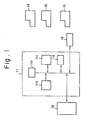
- Fig. 1 is a block diagram of a conventional robot control system of this kind.
- numeral 11 denotes a robot control device constituted by a computer and having a processor lla comprising a microcomputer or the like, a control program memory llb for controlling teaching, playback, editing and the like, a data memory llc for storing robot command data created on the basis of data entered from a teaching box to be described later, and a working memory lld for storing the current position, along each axis, of the robot hand which operates in a cylindrical coordinate system, and for storing data memory addresses, the operating speed of the hand, service codes indicating the kind of service, to be performed by the robot, etc.
- the data memory llc includes minor regions at addresses 0 to 299, each minor region storing robot command data comprising operating speed V0, coordinates that indicate the position of a commanded point, namely coordinates RO(position along the direction of arm extension and retraction), Z0(position along the vertical direction), 80(position along the direction of swiveling), as well as a maximum of five service codes for services executed at the commanded point, as shown in Fig. 2 which is an illustrative view of a storage region in data memory llc.
- Numeral 12 denotes a teaching box having various buttons, for teaching robot operations, as well as numerical devices, etc.
- Numeral 13 denotes a robot which operates on the basis of a cylindrical coordinate system.
- Numerals 14, 15 and 16 denote machine tools, such as lathes, serviced-by the robot.
- the position of the commanded point is taught by operating, one after another, the jog buttons for each axis of the cylindrical coordinate system. Since the teaching operation must be performed for each and every machine tool, the operation is extremely troublesome. In particular, in the case of a lathe or the like, the hand must be moved at right angles to the chuck surface in order to load and unload a workpiece in reliable fashion. Teaching such movement using the conventional cylindrical coordinate system is very troublesome.
- an object of the present invention is to provide a robot control system which enables a robot that operates in a cylindrical coordinate system to be taught using a rectangular coordinate system.
- Another object of the present invention is to provide a robot control system which enalbes what is taught in a rectangular coordinate system at one commanded point to be utilized at another commanded point as well.
- teaching means for instructing and teaching robot actions on the basis of a rectangular coordinate system, as well as rectangular-to-cylihdrical coordinate conversion means for converting the instructions in rectangular coordinates from the teaching means into command data in sylindrical coordinates.
- teaching means for instructing and teaching robot actions on the basis of a rectangular coordinate system
- rectangular-to-cylihdrical coordinate conversion means for converting the instructions in rectangular coordinates from the teaching means into command data in sylindrical coordinates.
- coordinate conversion mrans are provided for converting corresponding command data into other command data in accordance with the difference between the cylindrical coordinate values of the two origins.
- Fig. 1 is a block diagram of a conventional robot control system
- Fig. 2 is an illustrative view for describing an example of robot command data stored in a data memory shown in the block diagram of Fig. 1
- Figs. 3 and 4 are schematic illustrative views of a robot control system according to the present invention
- Figs. 5, 6 and 7 are circuit block diagrams each illustrating an embodiment of a robot control system according to the present invention.
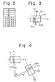
- Figs. 3 and 4 are illustrative views for describing the operation of a robot control system according to the present invention.
- Numerals 21 through 22 denote machine tools such as lathes, 21a, 22a denote chucks on the lathes, and 23 denotes the distal end of a robot hand.
- the end 23 of the robot hand is shown gripping a workpiece that is being attached to the chuck 21a of lathe 21.
- a rectangular coordinate system (Fig. 3) is established for the machine tool serviced by the accompanying robot, and the robot actions are taught on the basis of this rectangular coordinate system. That is, the hand 23 is made parallel to the surface of chuck 21a, and is then centered on the chuck. The hand direction at this time (the direction parallel to the surface of chuck 21a) is taken as the Y-axis, and the center direction (the direction orthogonal to the surface of chuck 21a) is taken as the X-axis. This establishes a rectangular coordinate system the origin whereof is set as the final target position.
- the teaching box 12 is provided with four jog buttons for commanding jog feeds in the +X, -X, +Y and -Y directions, respectively (a single changeover switch may be provided so that these jog buttons may also serve as cylindrical coordinate system jog buttons), and with rectangular + cylindrical coordinate conversion means. Accordingly, when the +X, +Y jog buttons are
- pulses are generated along the R- and 8-axial directions of the cylindrical coordinate system under the control of the rectangular ⁇ cylindrical coordinate conversion means in such fashion that the hand 23 moves along the commanded X or Y axis. These pulses therefore are counted up or down, in accordance with the direction of movement, by current position counters for the R and ⁇ axes.
- the content of these registers are stored in the data memory at the time that the commanded point is reached (the point at which the hand 23 reaches the chuck 21a, for example), this ends the teaching of position in the cylindrical coordinate system by means of the rectangular coordinate system input.
- rectangular + cylindrical coordinate conversion means are provided. Further, in a case where the commanded point is a point P1 which is +50mm along the X axis from the origin P20 of the rectangular coordinate system, are entered by means of the teaching box, after which the rectangular coordinates of the point Pl are converted into cylindrical coordinates by the rectangular ⁇ cylindrical coordinate conversion means to provide the taught data of the position.
- Fig. 5 is a block diagram illustrating an embodiment of a robot control device in a-robot control system according to the present invention.
- numeral 101 denotes a teaching box.
- +XJ, -XJ, +YJ, -YJ denote manually operable jog buttons for commanding the jog feed of a robot hand in the directions of the X and Y axes, respectively
- PB denotes a position teaching button
- SB an S-code button
- TK a ten-key for entering numerical values.
- Numeral 102 designates a pulse generator for generating jog feed pulses when each of the jog buttons is depressed.
- Numeral 103 denotes rectangular coordinate system information storage means for storing information AS on the abovementioned recangular coordinate systems (Figs. 3 and 4) established for each machine tool (which information may be the coordinate values of the origin expressed in cylindrical coordinate systems R, Q, by way of example).
- Numeral 104 denotes rectangular + cylindrical coordinate conversion means for converting pulses JP, generated by the pulse generator 102, into R-axis pulses Rp and 8-axis pulses ⁇ p so as to move the hand along the X or Y axes, based on the rectangular coordinate system information AS and on button information BS indicative of which jog button is being depressed.
- the rectangular ⁇ cylindrical coordinate conversion means 104 is composed of an arithmeric circuit and pulse generating circuit.
- Numerals 105R, 1056 denote current position registers 'for the R and ⁇ axes.
- the registers 105R, 105 ⁇ store the current positions Ra, 8a along the R and 8 axes by counting up or counting doen thw R-axis pulses Rp and 6-axis pulses ⁇ p, respectively, in accordance with the direction of movement.
- Numerals 106, 107 denote speed and S-code registers, respectively, for storing an operating speed V and S-code entered by the teaching box 101.
- Numeral 108 denotes a data memory (Fig. 2) for storing robot command data, 109 a write control circuit, 110 an address register in which the address of the data memory 108 is set, and 111 a decoder for decoding the address set in the address register.
- the data memory 108 is connected to the processor lla and control program memory llb through a data bus, just as the data memory llc of Fig. 1.
- the pulse generator 102 When the teach operation is selected on the teaching box 101 and the jog button +XJ for the X-axis direction is held depressed, the pulse generator 102 generates the jog pulses JP.
- the rectangular ⁇ cylindrical coordinate conversion means 104 converts the jog pulses JP into the R-axis pulses Rp and ⁇ -axis pulses ⁇ p, which are delivered as output signals, so as to move the hand in the +X-axis direction.
- R-axis pulses Rp and ⁇ -axis pulses p enter respective servo circuits (not shown) of the robot 13 and serve to extend, retract and swivel the hand of the robot 13 and to move the hand in its entirely along the X-axis.
- the pulses Rp, ⁇ p are also counted up or counted down, in accordance with the direction of movement, by the R-axis current position counter 105R and ⁇ -axis current position counter 1056.
- the generation of the jog pulses JP ceases and, hence, so does the generation of the R-axis pulses Rp and 8-axis pulses ⁇ p. The hand therefore stops moving.
- the teaching box 101 produces a signal PBS and the write control circuit 109 writes Ra, ea and V into the data memory 108 at the address set by the address register 110.
- the S-code is subsequently taught in the same manner as practiced conventionally, the S-code is likewise written into the data memory 108 at the corresponding address, thereby ending the teaching of the robot actions at the commanded point.
- teaching box 101 is provided solely with jog buttons of a rectangular coordinate system.
- teaching box also includes jog buttons of a cylindrical coordinate system, namely for +R, +6 and +Z axes and the like (where the same buttons may be used conjointly for the rectangular and cylindrical coordinate system jog buttons), wherein teaching may be conducted on the basis of the rectangular coordinate system or on the basis of the cylindrical coordinate system, as desired.
- the jog pulses produced by working such cylindrical coordinate system jog buttons are the R-axis pusles Rp and 8-axis pulses 6p. These outputs are therefore applied directly to the R-axis current position counter 105R and ⁇ -axis current position counter 105 .
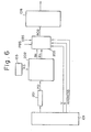
- Fig. 6 is a block diagram illustrating another embodiment of a robot control apparatus according to the present invention, exemplifying the creation and teaching of robot command data by means of an editing function.
- numeral 101 denotes a teaching box having a ten-key, 103 a rectangular coordinate system information storage means, and 108 a data memory.
- Numeral 201 designates a position register for storing position data PD, in a rectangular coordinate system, indicative of a commanded point. The position data PD is entered by means of the ten-key on teaching box 101.
- Numeral 202 represents rectangular ⁇ cylindrical coordinate conversion means for converting the positional data PD in rectangular coordinates into cylindrical coordinate values Rn, 8n, on the basis of rectangular coordinate system information AS.
- Numeral 203 represents editing means for editing robot command data.
- the editing means 203 receives the cylindrical coordinate values 8n, Rn as well as the operating speed V, S-code and addresses, etc., entered by the ten-key of the teaching box 101, and functions to combine these inputs to create robot command data RCD and store the robot command data in the data memory 108.
- data memory 108 is connected to the processor lla and control program memory llb via a data bus, as described above with reference to Fig. 1.
- the rectangular cylindrical coordinate conversion means 202 Upon receipt of the position data PD, the rectangular cylindrical coordinate conversion means 202 performs a rectangular-to-cylindrical coordinate conversion using the rectangular coordinate information P20 and rectangular coordinate value X50 specified by the position data, and provides the editing means 203 with the cylindrical coordinate values Rn, 6n.
- the rectangular + cylindrical coordinate conversion means 202 has the same construction as that of the conversion means shown in Fig. 5.
- the position teach button signal PBS goes to logical "1", whereby the editing means 203 writes Rn, ⁇ n and V into the previously set address of data memory 108.
- SBS denotes a signal produced by depressing the S-code cutton.
- Fig. 7 is a block diagram illustrating another embodiment of a robot control apparatus according to the present invention, exemplifying a case wherein one item of robot command data is used in common for a plurality of machine tools.
- the arrangement of Fig. 6 is provided with coordinate conversion means 301 connected to the data memory 108.
- the angle ⁇ and the radial difference AR R1-R2 (Fig. 4), measured from the origin of the rectangular coordinate system of the reference machine tool (22 in Fig. 4, by way of example) to the origin of the rectangular coordinate system established for each machine tool (such as 21 in Fig. 4), are entered and stored in the coordinate conversion means 301 for each machine tool.
- the coordinate conversion means 301 reads the robot command data relating to the reference machine tool from the data memory 108, subjects the data to a coordinate conversion and writes the converted data into the data memory 108 at a predetermined, separate address.
- the robot command data relating to the reference machine tool can be converted by the coordinate conversion means into robot command data relating to another machine tool.
- a hand can be moved along an axis of a rectangular coordinate system by operating a single jog button in a case where teaching is performed manually.
- This enables a special operation, such as moving the hand at right angles to the chuck, to be performed through a simple manipulation.
- robot command data is created by an editing function
- the rectangular coordinate values of the commanded point need only be entered to create robot command data and perform teaching in a simple manner.
- the robot command data relating to a reference machine tool can be subjected to a coordinate conversion to produce robot command data relating to another machine tool, so that it suffices to perform a teaching operating for only a single machine tool, thereby simplifying teaching.
Landscapes
- Engineering & Computer Science (AREA)
- Robotics (AREA)
- Health & Medical Sciences (AREA)
- General Health & Medical Sciences (AREA)
- Orthopedic Medicine & Surgery (AREA)
- Mechanical Engineering (AREA)
- Physics & Mathematics (AREA)
- General Physics & Mathematics (AREA)
- Automation & Control Theory (AREA)
- Numerical Control (AREA)
Applications Claiming Priority (2)
| Application Number | Priority Date | Filing Date | Title |
|---|---|---|---|
| JP55186735A JPS57113114A (en) | 1980-12-30 | 1980-12-30 | Robot control system |
| JP186735/80 | 1980-12-30 |
Publications (2)
| Publication Number | Publication Date |
|---|---|
| EP0067877A1 true EP0067877A1 (de) | 1982-12-29 |
| EP0067877A4 EP0067877A4 (de) | 1985-11-07 |
Family
ID=16193725
Family Applications (1)
| Application Number | Title | Priority Date | Filing Date |
|---|---|---|---|
| EP19810903078 Withdrawn EP0067877A4 (de) | 1980-12-30 | 1981-11-18 | Roboter-steuersystem. |
Country Status (4)
| Country | Link |
|---|---|
| US (1) | US4511985A (de) |
| EP (1) | EP0067877A4 (de) |
| JP (1) | JPS57113114A (de) |
| WO (1) | WO1982002435A1 (de) |
Cited By (1)
| Publication number | Priority date | Publication date | Assignee | Title |
|---|---|---|---|---|
| EP0215271A1 (de) * | 1985-08-19 | 1987-03-25 | Siemens Aktiengesellschaft | Geschwindigkeitsüberwachungssystem für Industrieroboter oder dergleichen |
Families Citing this family (33)
| Publication number | Priority date | Publication date | Assignee | Title |
|---|---|---|---|---|
| JPS5962910A (ja) * | 1982-10-01 | 1984-04-10 | Matsushita Electric Ind Co Ltd | プレイバツクロボツトの制御方法 |
| US4617502A (en) * | 1983-06-30 | 1986-10-14 | Hitachi, Ltd. | Method and apparatus for controlling a robot hand along a predetermined path |
| JPS6149205A (ja) * | 1984-08-16 | 1986-03-11 | Seiko Instr & Electronics Ltd | ロボツト制御方式 |
| JPS61109109A (ja) * | 1984-10-31 | 1986-05-27 | Sankyo Seiki Mfg Co Ltd | 平面多関節型ロボツトの位置決め方法 |
| JPS61110204A (ja) * | 1984-11-02 | 1986-05-28 | Hitachi Ltd | 自動化装置の制御方法 |
| JPS61128319A (ja) * | 1984-11-28 | 1986-06-16 | Nippon Kogaku Kk <Nikon> | 駆動装置 |
| JPS61146482A (ja) * | 1984-12-20 | 1986-07-04 | 工業技術院長 | 異構造異自由度バイラテラル・マスタスレイブ・マニピユレ−タの制御装置 |
| JP2684359B2 (ja) * | 1985-02-22 | 1997-12-03 | ファナック 株式会社 | ロボットのワーク直交座標系設定装置 |
| JPH0631527B2 (ja) * | 1985-04-30 | 1994-04-27 | マツダ株式会社 | さく岩機のブ−ム位置決め装置 |
| KR900008539B1 (ko) * | 1985-05-30 | 1990-11-24 | 마쯔시다덴기산교 가부시기가이샤 | 로보트의 연속경로 제어방법 |
| JPS6225302A (ja) * | 1985-07-25 | 1987-02-03 | Fanuc Ltd | 数値制御装置 |
| JPH02100704A (ja) * | 1988-10-08 | 1990-04-12 | Fanuc Ltd | ロボットプログラミングチェック方式 |
| JPH02250782A (ja) * | 1989-03-20 | 1990-10-08 | Fanuc Ltd | 産業用ロボットの手動介入方式 |
| US5485552A (en) * | 1990-12-18 | 1996-01-16 | Fanuc Ltd. | Method of creating a robot motion program |
| US7345672B2 (en) * | 1992-12-02 | 2008-03-18 | Immersion Corporation | Force feedback system and actuator power management |
| US6801008B1 (en) * | 1992-12-02 | 2004-10-05 | Immersion Corporation | Force feedback system and actuator power management |
| US5389865A (en) * | 1992-12-02 | 1995-02-14 | Cybernet Systems Corporation | Method and system for providing a tactile virtual reality and manipulator defining an interface device therefor |
| US5629594A (en) * | 1992-12-02 | 1997-05-13 | Cybernet Systems Corporation | Force feedback system |
| AU674435B2 (en) * | 1993-07-09 | 1996-12-19 | Akzo Nobel N.V. | Memory control device for an assay apparatus |
| US5625576A (en) * | 1993-10-01 | 1997-04-29 | Massachusetts Institute Of Technology | Force reflecting haptic interface |
| JP3274272B2 (ja) * | 1994-03-08 | 2002-04-15 | ファナック株式会社 | 座標系の手動送り方法並びにロボット制御装置 |
| WO1996034722A1 (en) * | 1995-05-02 | 1996-11-07 | Genmark Automation, Inc. | Two axis drive arm |
| US5741113A (en) * | 1995-07-10 | 1998-04-21 | Kensington Laboratories, Inc. | Continuously rotatable multiple link robot arm mechanism |
| US6121743A (en) * | 1996-03-22 | 2000-09-19 | Genmark Automation, Inc. | Dual robotic arm end effectors having independent yaw motion |
| US5789890A (en) * | 1996-03-22 | 1998-08-04 | Genmark Automation | Robot having multiple degrees of freedom |
| US6489741B1 (en) | 1998-08-25 | 2002-12-03 | Genmark Automation, Inc. | Robot motion compensation system |
| SE515980C2 (sv) * | 1999-07-13 | 2001-11-05 | Binar Ab | En metod för snabb förflyttning av ett arbetsobjekt i både horisontalled och vertikalled från en arbetsstation till en annan |
| JP3948189B2 (ja) * | 2000-03-28 | 2007-07-25 | 松下電器産業株式会社 | ロボットの教示装置 |
| WO2003080479A2 (en) * | 2002-03-20 | 2003-10-02 | Fsi International, Inc. | Systems and methods incorporating an end effector with a rotatable and/or pivotable body and/or an optical sensor having a light path that extends along a length of the end effector |
| US7411576B2 (en) * | 2003-10-30 | 2008-08-12 | Sensable Technologies, Inc. | Force reflecting haptic interface |
| JP4598865B2 (ja) * | 2009-02-17 | 2010-12-15 | ファナック株式会社 | 工作機械と組み合わせて使用するロボットの制御装置 |
| SG11201509135PA (en) * | 2013-05-07 | 2015-12-30 | Univ Singapore Technology & Design | A method and/ or system for magnetic localization |
| US12287622B2 (en) * | 2019-01-09 | 2025-04-29 | Mitsubishi Electric Corporation | Numerical control device and numerical control method |
Family Cites Families (7)
| Publication number | Priority date | Publication date | Assignee | Title |
|---|---|---|---|---|
| US3543910A (en) * | 1968-07-30 | 1970-12-01 | George C Devol | Work-head automatic motions controls |
| US3661051A (en) * | 1969-03-18 | 1972-05-09 | Unimation Inc | Programmed manipulator apparatus |
| US3909600A (en) * | 1972-06-26 | 1975-09-30 | Cincinnati Milacron Inc | Method and apparatus for controlling an automation along a predetermined path |
| JPS49134059A (de) * | 1973-04-27 | 1974-12-24 | ||
| JPS50112969A (de) * | 1974-02-18 | 1975-09-04 | ||
| US3920972A (en) * | 1974-07-16 | 1975-11-18 | Cincinnati Milacron Inc | Method and apparatus for programming a computer operated robot arm |
| US4163183A (en) * | 1975-10-28 | 1979-07-31 | Unimation, Inc. | Programmable automatic assembly system |
-
1980
- 1980-12-30 JP JP55186735A patent/JPS57113114A/ja active Pending
-
1981
- 1981-11-18 EP EP19810903078 patent/EP0067877A4/de not_active Withdrawn
- 1981-11-18 US US06/413,380 patent/US4511985A/en not_active Expired - Fee Related
- 1981-11-18 WO PCT/JP1981/000346 patent/WO1982002435A1/ja not_active Ceased
Cited By (2)
| Publication number | Priority date | Publication date | Assignee | Title |
|---|---|---|---|---|
| EP0215271A1 (de) * | 1985-08-19 | 1987-03-25 | Siemens Aktiengesellschaft | Geschwindigkeitsüberwachungssystem für Industrieroboter oder dergleichen |
| US4718078A (en) * | 1985-08-19 | 1988-01-05 | Siemens Aktiengesellschaft | System for controlling motion of a robot |
Also Published As
| Publication number | Publication date |
|---|---|
| EP0067877A4 (de) | 1985-11-07 |
| JPS57113114A (en) | 1982-07-14 |
| US4511985A (en) | 1985-04-16 |
| WO1982002435A1 (en) | 1982-07-22 |
Similar Documents
| Publication | Publication Date | Title |
|---|---|---|
| EP0067877A1 (de) | Roboter-steuersystem | |
| US5020001A (en) | Robot controller | |
| US4659971A (en) | Robot controlling system | |
| US5371836A (en) | Position teaching method and control apparatus for robot | |
| EP0076970B1 (de) | Verfahren zur Eingabe von Koordinatenpunkten eines gewünschten Weges für einen voreingestellten Roboter | |
| EP0172486B1 (de) | Spurfolgendes Robotergerät | |
| US4633409A (en) | Numerical control device | |
| GB1561256A (en) | Programmable manipulators | |
| US4424569A (en) | Method and apparatus for a numerical control device for controlling a machining device having a plurality of tools | |
| JP2728399B2 (ja) | ロボツトの制御方法 | |
| EP0062075B1 (de) | Numerisches steuersystem | |
| US4507738A (en) | Numerical control method | |
| EP0103428B1 (de) | Programmiergerät für eine numerische Steuerung | |
| WO1984004479A1 (fr) | Procede de controle d'interference d'outil | |
| CN115741701B (zh) | 一种力位混合机器人轨迹与动作引导系统及方法 | |
| EP0067880A1 (de) | Roboter-steuersystem | |
| EP0071378B1 (de) | Methode und Apparat zur numerischen Steuerung | |
| JPS61131105A (ja) | 刃物台を2台有する旋盤の制御方式 | |
| JPS62163109A (ja) | 数値制御装置 | |
| JPS62251901A (ja) | 多軸ロボツトの経路制御装置 | |
| US3818301A (en) | Multiplexed machine control apparatus | |
| US4958293A (en) | Digitizing method | |
| CN116529035A (zh) | 数值控制装置以及数值控制系统 | |
| EP0181406A1 (de) | Verfahren zur steuerung eines roboters | |
| US5773950A (en) | Program creating method for uniform-shape machining |
Legal Events
| Date | Code | Title | Description |
|---|---|---|---|
| PUAI | Public reference made under article 153(3) epc to a published international application that has entered the european phase |
Free format text: ORIGINAL CODE: 0009012 |
|
| 17P | Request for examination filed |
Effective date: 19820914 |
|
| AK | Designated contracting states |
Designated state(s): DE FR GB |
|
| 17Q | First examination report despatched |
Effective date: 19870429 |
|
| STAA | Information on the status of an ep patent application or granted ep patent |
Free format text: STATUS: THE APPLICATION IS DEEMED TO BE WITHDRAWN |
|
| 18D | Application deemed to be withdrawn |
Effective date: 19870910 |
|
| RIN1 | Information on inventor provided before grant (corrected) |
Inventor name: INABA, HAJIMU Inventor name: SAKAKIBARA, SHINSUKE |