EP0067958A2 - Procédé pour diviser du bois rond en plusieurs sections de longueurs préalablement déterminées - Google Patents
Procédé pour diviser du bois rond en plusieurs sections de longueurs préalablement déterminées Download PDFInfo
- Publication number
- EP0067958A2 EP0067958A2 EP82104117A EP82104117A EP0067958A2 EP 0067958 A2 EP0067958 A2 EP 0067958A2 EP 82104117 A EP82104117 A EP 82104117A EP 82104117 A EP82104117 A EP 82104117A EP 0067958 A2 EP0067958 A2 EP 0067958A2
- Authority
- EP
- European Patent Office
- Prior art keywords
- conveyor
- log
- saw
- transverse
- longitudinal
- Prior art date
- Legal status (The legal status is an assumption and is not a legal conclusion. Google has not performed a legal analysis and makes no representation as to the accuracy of the status listed.)
- Granted
Links
- 238000000034 method Methods 0.000 title claims description 20
- 239000002023 wood Substances 0.000 claims abstract description 20
- 238000005520 cutting process Methods 0.000 description 6
- 230000001174 ascending effect Effects 0.000 description 2
- 230000006978 adaptation Effects 0.000 description 1
- 238000003754 machining Methods 0.000 description 1
- 230000000284 resting effect Effects 0.000 description 1
- 230000002123 temporal effect Effects 0.000 description 1
Images

Classifications
-
- B—PERFORMING OPERATIONS; TRANSPORTING
- B27—WORKING OR PRESERVING WOOD OR SIMILAR MATERIAL; NAILING OR STAPLING MACHINES IN GENERAL
- B27B—SAWS FOR WOOD OR SIMILAR MATERIAL; COMPONENTS OR ACCESSORIES THEREFOR
- B27B25/00—Feeding devices for timber in saw mills or sawing machines; Feeding devices for trees
- B27B25/04—Feeding devices for timber in saw mills or sawing machines; Feeding devices for trees with feed chains or belts
-
- B—PERFORMING OPERATIONS; TRANSPORTING
- B27—WORKING OR PRESERVING WOOD OR SIMILAR MATERIAL; NAILING OR STAPLING MACHINES IN GENERAL
- B27B—SAWS FOR WOOD OR SIMILAR MATERIAL; COMPONENTS OR ACCESSORIES THEREFOR
- B27B31/00—Arrangements for conveying, loading, turning, adjusting, or discharging the log or timber, specially designed for saw mills or sawing machines
-
- B—PERFORMING OPERATIONS; TRANSPORTING
- B27—WORKING OR PRESERVING WOOD OR SIMILAR MATERIAL; NAILING OR STAPLING MACHINES IN GENERAL
- B27B—SAWS FOR WOOD OR SIMILAR MATERIAL; COMPONENTS OR ACCESSORIES THEREFOR
- B27B5/00—Sawing machines working with circular or cylindrical saw blades; Components or equipment therefor
- B27B5/16—Saw benches
- B27B5/22—Saw benches with non-feedable circular saw blade
- B27B5/228—Cross-cutting automatically laterally-fed travelling workpieces; Reducing lumber to desired lengths
Definitions
- the invention relates to a method for dividing logs into a plurality of log sections of a predetermined length according to the preamble of claim 1.
- a method of the type mentioned is known (DE-OS 28 42 935). After the round wood conveyed in its longitudinal direction has been cut to length by the first saw cut so that a round wood piece is formed, the length of which corresponds to the sum of the predetermined length of at least two round wood sections to be produced, this round wood piece is transferred to a conveyor bed by a cross transfer device, there. positioned in its longitudinal direction and - while it is resting on the conveyor bed - divided into the desired log sections by a further saw cut. While this second saw cut is taking place, no further piece of round wood can be transferred and no longitudinal positioning process can be carried out on the conveyor bed.
- the working speed of the known method is therefore limited by the fact that the work steps of transferring the log piece to the conveyor bed, the longitudinal positioning of the log piece on the conveyor bed, dividing the log piece into the desired log sections and further transport can only be carried out one after the other in time.
- the object of the invention is therefore to provide a method of the type outlined in the preamble of claim 1 in such a way that a substantial increase in working capacity, i. H. throughput of logs is achieved in order to allow adaptation to the increased capacities of modern sawing and profiling systems.
- This object is achieved in that the further saw cut is carried out when the log piece is conveyed in the transverse direction, while at the same time a further, first saw cut is carried out.
- the known method has achieved a temporal and spatial staggering of the saw cuts, with the first saw cut being carried out on a conveyed log log when the previously cut log piece is still subjected to the second saw cut.
- This allows a significant increase in the capacity for the cutting process to be achieved with comparatively little effort.
- This makes it possible to load modern, high-performance sawing and profiling systems with a single one-piece station, which avoids the considerable human and technical extra work for a second one-station, otherwise would be necessary to achieve an adjustment of the loading speed to the working speed of the sawing or profiling system.
- the simultaneous execution of several saw cuts on the same log which could also bring about an increase in capacity, would be associated with considerable difficulties which stand in the way of practical implementation.
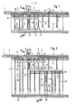
- the devices according to FIGS. 1 and 2 and according to FIGS. 3 and 4 have in common that the log 1 to be cut is conveyed upwards in the longitudinal direction on a chain conveyor track 2 and fed to a first circular saw 3 which is arranged in a gap in the chain conveyor track 2 .
- the chain conveyor track 2 is connected to a positioning device, not shown, which has, for example, fold-away and / or longitudinally adjustable stops or which - as provided in the exemplary embodiment shown - has a pulse control with which the previously measured log 1 is conveyed to the position in which the circular saw 3 cuts off a piece of round wood 1 a with a first saw cut, in that the circular saw 3 is advanced transversely to the chain conveyor track 2.
- the length of the cut log piece 1a corresponds in the example according to FIGS. 1 and 2 to the sum of the lengths of two log sections 1b and 1c which are to be achieved by the distribution process.
- the cut round piece of wood 1a has a length which corresponds to the sum of three round wood sections 1b, 1d and 1e taking into account the saw cut joints.
- the log piece 1a is ejected by a transverse transfer device 4, which has, for example, movable punches, onto a roller conveyor bed 5 arranged parallel to the chain conveyor bed 2.
- a transverse transfer device 4 which has, for example, movable punches
- the piece of log 1a is in its Moved in the longitudinal direction and positioned by moving z.] 3 against adjustable stops 6.
- the roller conveyor bed is located in the region of an ascending chain cross conveyor 7, which has a plurality of chains 8 arranged next to one another, each of which is provided with drivers 9.
- the cross conveyor 7 is driven intermittently and takes over with its drivers 9 in each movement step: a log piece 1a from the roller conveyor bed 5.
- the log piece 1a When the log piece 1a is conveyed crosswise, it is moved against a further circular saw 10 arranged in the area of the cross conveyor 7, which cuts the log piece 1a into the Sections 1b and 1c divided, the predetermined length of which was set by the positioning process on the roller conveyor bed 5.
- the log sections 1b and 1c at the upper end of the cross conveyor 7 arrive at a pivotable transfer device 11, through which they are fed to a chain longitudinal conveyor 12, which carries the log sections 1b and 1c, for example, to a sorting device downstream sawing and profiling system promotes.
- the transfer device can be divided into separately operable sections in order to enable the individual transfer of the individual log sections.
- the circular saw 10 is mounted on a swivel arm 13 which can be swiveled by means of a pressure-actuated cylinder 14.
- a pressure-actuated cylinder 14 Depending on the thickness of the log, two different ways of working are possible. While the circular saw 10 is constantly in its upper position when cutting thinner round wood and the round wood is moved by the cross conveyor 7 against the circular saw 10 If the log is stronger, the log is conveyed into the sawing position when the circular saw 10 is initially lowered. In this position, the log is held by a hold-down device 15 only indicated in FIG. 2, while the circular saw 10 is pivoted upwards by the cylinder 14 and sawed through the log.
- the embodiment according to FIGS. 3 and 4 differs from the embodiment according to FIGS. 1 and 2 in that only the one log section 1b, which was separated from the log piece 1a when passing the circular saw 10, by the chain cross conveyor 7 in the described way to the chain conveyor 12 is moved.
- the log section 1c is fed by a shorter chain cross conveyor 7 'after the saw cut to a further roller conveyor bed 16, on which the log section 1c is positioned by longitudinal movement against an adjustable stop 17.
- a further chain conveyor 7 ′′ also arranged in an ascending manner, lifts the log section 1c from the roller conveyor bed 17 and feeds it to a circular saw 18, which is designed and arranged in a corresponding manner, as was described in connection with the circular saw 10
- Circular saw 18 divides the log section 1c into log sections 1d and 1e, which are then also transferred to the chain longitudinal conveyor 12 by a transfer device 11 '.
- the method according to the invention can also be carried out in such a way that no circular saw 3 is provided in the area of the chain longitudinal conveyor device 2.
- the log is here delivered to the roller conveyor 5 without a saw cut, positioned there in the longitudinal direction and fed to the circular saw 10.
- the log section 1c separated there is then cut into the desired log sections 1d and 1e by a further circular saw 18, similar to the device according to FIGS. 3 and 4.
Landscapes
- Life Sciences & Earth Sciences (AREA)
- Engineering & Computer Science (AREA)
- Mechanical Engineering (AREA)
- Wood Science & Technology (AREA)
- Forests & Forestry (AREA)
- Sorting Of Articles (AREA)
- Fish Paste Products (AREA)
- Debarking, Splitting, And Disintegration Of Timber (AREA)
- Communication Control (AREA)
Priority Applications (1)
| Application Number | Priority Date | Filing Date | Title |
|---|---|---|---|
| AT82104117T ATE21645T1 (de) | 1981-06-11 | 1982-05-12 | Verfahren zum zerteilen von rundholz in mehrere rundholzabschnitte vorgegebener laenge. |
Applications Claiming Priority (2)
| Application Number | Priority Date | Filing Date | Title |
|---|---|---|---|
| DE3123086A DE3123086C2 (de) | 1981-06-11 | 1981-06-11 | Verfahren und Vorrichtung zum Zerteilen von Rundholz in mehrere Rundholzabschnitte vorgegebener Länge |
| DE3123086 | 1981-06-11 |
Publications (3)
| Publication Number | Publication Date |
|---|---|
| EP0067958A2 true EP0067958A2 (fr) | 1982-12-29 |
| EP0067958A3 EP0067958A3 (en) | 1983-07-20 |
| EP0067958B1 EP0067958B1 (fr) | 1986-08-27 |
Family
ID=6134401
Family Applications (1)
| Application Number | Title | Priority Date | Filing Date |
|---|---|---|---|
| EP82104117A Expired EP0067958B1 (fr) | 1981-06-11 | 1982-05-12 | Procédé pour diviser du bois rond en plusieurs sections de longueurs préalablement déterminées |
Country Status (5)
| Country | Link |
|---|---|
| EP (1) | EP0067958B1 (fr) |
| AT (1) | ATE21645T1 (fr) |
| DE (1) | DE3123086C2 (fr) |
| FI (1) | FI70813C (fr) |
| ZA (1) | ZA824074B (fr) |
Family Cites Families (3)
| Publication number | Priority date | Publication date | Assignee | Title |
|---|---|---|---|---|
| US3799015A (en) * | 1971-09-02 | 1974-03-26 | T Bush | Log processing machine |
| US4007654A (en) * | 1975-09-25 | 1977-02-15 | Oleson Sumner R | Sawing apparatus of the pulpwood slasher type |
| AT364156B (de) * | 1978-09-29 | 1981-09-25 | Hammars Mekaniska Verkstad Ab | Vorrichtung zur teilung eines stammes in saegeholz und kurz- bzw. zellstoffholz |
-
1981
- 1981-06-11 DE DE3123086A patent/DE3123086C2/de not_active Expired
-
1982
- 1982-05-12 EP EP82104117A patent/EP0067958B1/fr not_active Expired
- 1982-05-12 AT AT82104117T patent/ATE21645T1/de not_active IP Right Cessation
- 1982-05-26 FI FI821871A patent/FI70813C/fi not_active IP Right Cessation
- 1982-06-10 ZA ZA824074A patent/ZA824074B/xx unknown
Also Published As
| Publication number | Publication date |
|---|---|
| FI70813B (fi) | 1986-07-18 |
| FI821871A0 (fi) | 1982-05-26 |
| DE3123086A1 (de) | 1982-12-30 |
| FI70813C (fi) | 1986-10-27 |
| EP0067958B1 (fr) | 1986-08-27 |
| ATE21645T1 (de) | 1986-09-15 |
| ZA824074B (en) | 1983-04-27 |
| DE3123086C2 (de) | 1983-07-28 |
| EP0067958A3 (en) | 1983-07-20 |
Similar Documents
| Publication | Publication Date | Title |
|---|---|---|
| EP0296161B1 (fr) | Procede et dispositif pour introduire des troncs d'arbre dans une machine de traitement | |
| AT402706B (de) | Adjustiermaschine und -verfahren | |
| WO1988000113A1 (fr) | Scie circulaire a coupe transversale pour couper des planches a longueur | |
| AT396890B (de) | Vorrichtung zum abstützen eines auf einer plattenaufteilsäge hergestellten langen und schmalen werkstückpakets | |
| DE3632263C2 (fr) | ||
| DE3028191A1 (de) | Buntaufteilanlage fuer plattenfoermige werkstuecke | |
| DE3830856C1 (fr) | ||
| EP0067958B1 (fr) | Procédé pour diviser du bois rond en plusieurs sections de longueurs préalablement déterminées | |
| DE3632018A1 (de) | Aufteilanlage fuer plattenfoermige werkstuecke | |
| DE3914625C2 (fr) | ||
| DE2501012A1 (de) | Verfahren und vorrichtung zum aufeinandersetzen von stapeln | |
| CH658016A5 (de) | Holzbearbeitungsmaschine zum zapfenschlagen und laengsprofilieren von hoelzern, insbesondere von fensterhoelzern. | |
| DE4212903C2 (fr) | ||
| DE4240636C2 (de) | Keilzinkenanlage mit Einfädelstation, Taktpresse und ggf. Ablängsäge | |
| DE3343809C2 (de) | Verfahren und Vorrichtung zum Transportieren und Bearbeiten von Werkstücken, insbesondere von Hölzern | |
| DE2054831A1 (de) | Vorrichtung zur automatischen Übergabe von Holzwerkstücken | |
| DE3317307C2 (fr) | ||
| DE19508401C1 (de) | Positioniersystem für Rundholzkappanlagen | |
| DE2842935C2 (de) | Verfahren und Vorrichtung zum Zerteilen eines Baumstamms | |
| DE3314175C1 (de) | Verfahren und Vorrichtung zum Ablängen von Holz | |
| EP1038643A2 (fr) | Ensemble de scies à ruban pour la découpe de troncs d'arbres, en particulier des quarts d'arbres | |
| DE2928086C2 (de) | Verfahren und Vorrichtung zum Besäumen von baumkantigen Brettern | |
| DE19701028C2 (de) | Vorrichtung zum Besäumen von Schnittgutstücken aus Holz | |
| DE3218464A1 (de) | Anlage zur abkappung von saegewaren | |
| EP0124650A2 (fr) | Machine pour travailler les deux extrémités d'objets en bois allongés |
Legal Events
| Date | Code | Title | Description |
|---|---|---|---|
| PUAI | Public reference made under article 153(3) epc to a published international application that has entered the european phase |
Free format text: ORIGINAL CODE: 0009012 |
|
| AK | Designated contracting states |
Designated state(s): AT BE CH FR GB LI NL SE |
|
| PUAL | Search report despatched |
Free format text: ORIGINAL CODE: 0009013 |
|
| AK | Designated contracting states |
Designated state(s): AT BE CH FR GB LI NL SE |
|
| 17P | Request for examination filed |
Effective date: 19831019 |
|
| GRAA | (expected) grant |
Free format text: ORIGINAL CODE: 0009210 |
|
| AK | Designated contracting states |
Kind code of ref document: B1 Designated state(s): AT BE CH FR GB LI NL SE |
|
| REF | Corresponds to: |
Ref document number: 21645 Country of ref document: AT Date of ref document: 19860915 Kind code of ref document: T |
|
| PG25 | Lapsed in a contracting state [announced via postgrant information from national office to epo] |
Ref country code: SE Effective date: 19860831 |
|
| ET | Fr: translation filed | ||
| RAP2 | Party data changed (patent owner data changed or rights of a patent transferred) |
Owner name: GEBRUEDER LINCK, MASCHINENFABRIK GATTERLINCK GMB |
|
| BECN | Be: change of holder's name |
Effective date: 19860827 |
|
| NLT2 | Nl: modifications (of names), taken from the european patent patent bulletin |
Owner name: GEBRUEDER LINCK, MASCHINENFABRIK 'GATTERLINCK' GMB |
|
| PLBE | No opposition filed within time limit |
Free format text: ORIGINAL CODE: 0009261 |
|
| STAA | Information on the status of an ep patent application or granted ep patent |
Free format text: STATUS: NO OPPOSITION FILED WITHIN TIME LIMIT |
|
| 26N | No opposition filed | ||
| PGFP | Annual fee paid to national office [announced via postgrant information from national office to epo] |
Ref country code: GB Payment date: 19890228 Year of fee payment: 8 |
|
| PGFP | Annual fee paid to national office [announced via postgrant information from national office to epo] |
Ref country code: BE Payment date: 19890313 Year of fee payment: 8 |
|
| PGFP | Annual fee paid to national office [announced via postgrant information from national office to epo] |
Ref country code: NL Payment date: 19890531 Year of fee payment: 8 |
|
| PG25 | Lapsed in a contracting state [announced via postgrant information from national office to epo] |
Ref country code: GB Effective date: 19900512 |
|
| PG25 | Lapsed in a contracting state [announced via postgrant information from national office to epo] |
Ref country code: BE Effective date: 19900531 |
|
| BERE | Be: lapsed |
Owner name: GEBRUDER LINCK MASCHINENFABRIK -GATTERLINCK- G.M. Effective date: 19900531 |
|
| PG25 | Lapsed in a contracting state [announced via postgrant information from national office to epo] |
Ref country code: NL Effective date: 19901201 |
|
| GBPC | Gb: european patent ceased through non-payment of renewal fee | ||
| NLV4 | Nl: lapsed or anulled due to non-payment of the annual fee | ||
| PGFP | Annual fee paid to national office [announced via postgrant information from national office to epo] |
Ref country code: AT Payment date: 19940527 Year of fee payment: 13 |
|
| PG25 | Lapsed in a contracting state [announced via postgrant information from national office to epo] |
Ref country code: AT Effective date: 19950512 |
|
| PGFP | Annual fee paid to national office [announced via postgrant information from national office to epo] |
Ref country code: FR Payment date: 20010511 Year of fee payment: 20 |
|
| PGFP | Annual fee paid to national office [announced via postgrant information from national office to epo] |
Ref country code: CH Payment date: 20010525 Year of fee payment: 20 |
|
| PG25 | Lapsed in a contracting state [announced via postgrant information from national office to epo] |
Ref country code: LI Free format text: LAPSE BECAUSE OF EXPIRATION OF PROTECTION Effective date: 20020511 Ref country code: CH Free format text: LAPSE BECAUSE OF EXPIRATION OF PROTECTION Effective date: 20020511 |
|
| REG | Reference to a national code |
Ref country code: CH Ref legal event code: PL |