EP0068202A1 - Röntgenuntersuchungsgerät - Google Patents
Röntgenuntersuchungsgerät Download PDFInfo
- Publication number
- EP0068202A1 EP0068202A1 EP82105040A EP82105040A EP0068202A1 EP 0068202 A1 EP0068202 A1 EP 0068202A1 EP 82105040 A EP82105040 A EP 82105040A EP 82105040 A EP82105040 A EP 82105040A EP 0068202 A1 EP0068202 A1 EP 0068202A1
- Authority
- EP
- European Patent Office
- Prior art keywords
- diaphragm
- examination apparatus
- ray examination
- ray
- tube
- Prior art date
- Legal status (The legal status is an assumption and is not a legal conclusion. Google has not performed a legal analysis and makes no representation as to the accuracy of the status listed.)
- Granted
Links
- 230000005855 radiation Effects 0.000 claims abstract description 20
- 229910000831 Steel Inorganic materials 0.000 claims 1
- 239000010959 steel Substances 0.000 claims 1
- 230000000873 masking effect Effects 0.000 description 3
- 238000004519 manufacturing process Methods 0.000 description 2
- 238000003780 insertion Methods 0.000 description 1
- 230000037431 insertion Effects 0.000 description 1
- 238000012423 maintenance Methods 0.000 description 1
- 230000001960 triggered effect Effects 0.000 description 1
Images

Classifications
-
- G—PHYSICS
- G03—PHOTOGRAPHY; CINEMATOGRAPHY; ANALOGOUS TECHNIQUES USING WAVES OTHER THAN OPTICAL WAVES; ELECTROGRAPHY; HOLOGRAPHY
- G03B—APPARATUS OR ARRANGEMENTS FOR TAKING PHOTOGRAPHS OR FOR PROJECTING OR VIEWING THEM; APPARATUS OR ARRANGEMENTS EMPLOYING ANALOGOUS TECHNIQUES USING WAVES OTHER THAN OPTICAL WAVES; ACCESSORIES THEREFOR
- G03B42/00—Obtaining records using waves other than optical waves; Visualisation of such records by using optical means
- G03B42/02—Obtaining records using waves other than optical waves; Visualisation of such records by using optical means using X-rays
Definitions
- the invention relates to an X-ray examination apparatus with an X-ray tube held at one end of a tube image support with a flange-mounted radiation source and an X-ray tube at the other end of the tube image support at a constant distance from the X-ray tube, with the image support held in alignment with it, with means for the central positioning of image layers predefined formats.
- the invention has for its object to develop an inexpensive X-ray examination device by meaningful restriction to essential functions. Not only should it be inexpensive to manufacture, but it should also be so simple and clear in terms of maintenance and handling that it can also be used by untrained auxiliary staff in developing countries.
- the radiation diaphragm therefore includes, according to the invention, an aperture plate which can be rotated about an axis arranged next to the beam cone to be masked openings that can be swiveled into the beam cone and are adapted to the predetermined formats of the image layer.
- an aperture plate which can be rotated about an axis arranged next to the beam cone to be masked openings that can be swiveled into the beam cone and are adapted to the predetermined formats of the image layer.
- the masking can be significantly improved with regard to its edge sharpness if, in a further development of the invention, two different diaphragm disks are attached one behind the other on the same axis and their openings, which can be rotated together in the beam cone, hide the same beam cone.
- the dimensions of the radiation diaphragm can be significantly reduced if the axis at its end facing the X-ray tube is mounted closer to the central beam than at its other end.
- the smaller diaphragm disk facing the focus can be kept even smaller and can also be accommodated in a more space-saving manner than if the axis is aligned parallel to the central beam or the masking axis.
- the operation of the radiation diaphragm can be simplified if, in a further development of the invention, a diaphragm disk protrudes laterally from the housing of the radiation diaphragm. This has the advantage that there is no need for a special, failure-prone aperture drive. Instead, the front panel can be turned by hand until the desired format is displayed.
- the exact setting of the radiation diaphragm is facilitated if the diaphragm disk has notches which can be brought into engagement with a detent assigned to them and fastened in the housing. This eliminates the exact setting of the angle of rotation of the diaphragm disk because it engages in the respective centered position.
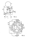
- FIG. 1 shows an X-ray examination device 1 in which the X-ray tube 2 is held on a tube image layer support 5 which is height-adjustable on a stand column 3 and rotatable about a horizontal axis 4.
- a radiation diaphragm 6 is flanged onto the X-ray tube 2.
- a cassette holder 7 is attached as an image support at a constant distance from the x-ray tube and aligned with it.
- the cassette holder 7 has an insertion slot 8, through which X-ray film cassettes (not shown) can be inserted.
- the clamping device of the cassette holder of which only the Adjustment knob 9 is shown, only allow four different formats 10, 11, 12, 13 to be held.
- a circular diaphragm 16 is provided on the side.
- the protruding edge of the diaphragm disk 16 bears the same color 17 as the format limitation 12 painted on the side of the cassette holder facing the x-ray tube, to which the cone of rays 18 faded in by the diaphragm 6 is adjusted.
- the diaphragm disk 16 protruding laterally from the diaphragm housing 15 is fastened on an axis 19; on which there is a second smaller diaphragm disk 20, somewhat closer to the X-ray tube 2.
- the openings 21, 22 swung into the beam cone 18 of the two rigidly connected to each other on the same axis 19.
- E n aperture disks 16, 20 mask exactly the same beam cone. This also applies to the other openings 23, 24, 25, 26 which can be rotated together with the two diaphragm disks into the beam cone (FIG. 3).
- FIG. 3 also shows a catch 28 installed in the panel housing 16 and clearly shown in FIG. 3.
- Fig. 3 it can be seen that the catch 28 can be brought into engagement in notches 29, 30, 31, 32 provided on the circumference of the large diaphragm disk 16. These notches are arranged in such a way that the catch 28 engaging in a notch holds the diaphragm disk 16 in the position in which one of its openings 21, 23, 25, 26 is centered on the central beam 27 of the beam cone which can be suppressed.
- the edge of the large aperture disc 16 distributed over its circumference so many different colored sections 33, 54, 35, 36 carries, as openings 21, 23, 25, 26 are present.
- the colored sections are positioned in such a way that, with each snap-in blanking format, the color assigned to this format appears on the edge of the aperture disk 16 protruding from the aperture housing 15.
- the doctor selects an X-ray film cassette that is adapted to the examination area. He can only choose between the four formats 10, 11, 12, 13 drawn on the side of the cassette holder facing the X-ray tube. If he uses an X-ray film cassette of one of these formats, the clamping means holding the X-ray film cassette in this format only with appropriate adjustment of the setting button 9 on the cassette holder 7, this color can be read off the setting button in a manner not shown here. It also corresponds to the color with which this format is recorded on the side of the cassette holder 7 facing the X-ray tube 2. Now the operator only needs to rotate the aperture disk 16 until this same color appears on the edge of the large aperture disk 16 protruding from the housing 15 of the radiation aperture 6. If the catch 28 then engages in the corresponding notch 29, 30, 31, 32 at the edge of the diaphragm disk 16, this format is exactly masked out by the radiation diaphragm 6. The recording can be triggered.
- the housing 15 of the radiation diaphragm 6 can be kept smaller, because for the small diaphragm disk 20 facing the X-ray tube 2, the distance from the axis 19 to the central beam 27 becomes smaller and therefore this diaphragm disk can be even smaller than if the axis were aligned parallel to the central beam. Except this is saved by the inclined position of the axis 19 due to the diagonal setting of this smaller aperture 20 more space. Since the radiation diaphragm 6 does not contain a separate drive and, apart from the axis 19 with the diaphragm disks 16, 20 fixed immovably thereon, contains no moving parts, disturbances are not to be expected.
- a sheet film changer or an X-ray target device could also be used.
Landscapes
- Physics & Mathematics (AREA)
- General Physics & Mathematics (AREA)
- Apparatus For Radiation Diagnosis (AREA)
- Radiography Using Non-Light Waves (AREA)
Abstract
Description
- Die Erfindung bezieht sich auf ein Röntgenuntersuchungsgerät mit einer an einem Ende eines Röhre-Bildschichtträgers gehalterten Röntgenröhre mit angeflanschter Strahlenquelle und einem am anderen Ende des Röhre-Bildschichtträgers in konstantem Abstand von der Röntgenröhre, zu dieser ausgerichtet gehaltenen Bildschichtträger mit Mitteln zur zentrischen Positionierung von Bildschichten bestimmter vorgegebener Formate.
- Bei der überwiegenden Mehrzahl der in der medizinischen Technik anfallenden Untersuchungen kommt man mit einem einzigen Film-Fokus-Abstand aus. Die Filmformate und die zugehörigen Röntgenfilmkassetten sind in den meisten Ländern in bestimmten Größenverhältnissen zueinander abgestuft. Diese Abstufung variiert jedoch in manchen Ländern gegenüber derjenigen in anderen Ländern, so daß sich in der Praxis eine sehr große Vielfalt von Formaten ergibt.
- Der Erfindung liegt die Aufgabe zugrunde, durch sinnvolle Beschränkung auf wesentliche Funktionen ein preiswertes Röntgenuntersuchungsgerät zu entwickeln. Es soll nicht nur in der Herstellung preiswert sondern auch in der Wartung und Handhabung so einfach und übersichtlich sein, daß es auch in den Entwicklungsländern mit ungeschultem Hilfspersonal bedienbar ist.
- Bei einem Röntgenuntersuchungsgerät der eingangs genannten Art beinhaltet daher die Strahlenblende erfindungsgemäß eine um eine neben dem auszublendenden Strahlenkegel angeordnete Achse drehbare Blendenscheibe mit in den Strahlenkegel einschwenkbaren, den vorbestimmten Formaten der Bildschicht angepaßten Durchbrüchen. Eine solche Strahlenblende ist nicht nur in ihrer Herstellung besonders einfach, sie ist zugleich auch robust, so gut wie gar nicht störanfällig und in ihrer Bedienung übersichtlich.
- Die Ausblendung kann hinsichtlich ihrer Randschärfe wesentlich verbessert werden, wenn in Weiterbildung der Erfindung zwei verschiedene Blendenscheiben hintereinander auf der gleichen Achse befestigt sind und ihre gemeinsam in den Strahlenkegel drehbaren Durchbrüche den jeweils gleichen Strahlenkegel ausblenden. Durch solche hintereinandergeschalteten Ausblendebenen, die den gleichen vom gleichen Fokus ausgehenden Strahlenkegel ausblenden, wird eine starke Verringerung des Randschattenbereichs erreicht, weil damit auch afokale Röntgenstrahlen ausblendbar sind.
- Die Abmessungen der Strahlenblende lassen sich bedeutend verringern, wenn die Achse an ihrem der Röntgenröhre zugewandten Ende näher zum Zentralstrahl gelagert ist als an ihrem anderen Ende. Hierdurch kann die kleinere dem Fokus zugewandte Blendenscheibe noch kleiner gehalten und außerdem auch noch platzsparender untergebracht werden, als wenn die Achse parallel zum Zentralstrahl, bzw. der Ausblendachse, ausgerichtet ist.
- Die Bedienung der Strahlenblende läßt sich vereinfachen, wenn in Weiterbildung der Erfindung eine Blendenscheibe seitlich aus dem Gehäuse der Strahlenblende vorsteht. Dies hat den Vorteil, daß auf einen besonäeren, störanfälligen Blendenantrieb verzichtet werden kann. Stattdessen kann die Blendenscheibe an ihrem vorstehenden Rand von Hand gedreht werden, bis das gewünschte Format eingeblendet ist.
- Die exakte Einstellung der Strahlenblende wird erleichtert, wenn die Blendenscheibe Kerben trägt, die mit einer ihnen zugeordneten, im Gehäuse befestigten, Raste in Eingriff bringbar sind. Hierdurch entfällt das exakte Einstellen des Drehwinkels der Blendenscheibe, weil diese in der jeweiligen zentrierten Stellung einrastet.
- Weitere Einzelheiten der Erfindung werden anhand eines in den Figuren dargestellten Ausführungsbeispiels erläutert. Es zeigen:
- Fig. 1 eine schaubildliche Ansicht.des Röntgenuntersuchungsgerätes mit der erfindungsgemäßen Strahlenblende,
- Fig. 2 eine schematische Darstellung der Anordnung der Blendenscheiben in der Strahlenblende, und
- Fig. 3 eine Aufsicht auf die den Untersuchungsobjekt zugewandte Blendenscheibe bei teilweise aufgebrochenem Gehäuse der Strahlenblende.
- In der Fig. 1 erkennt man ein Röntgenuntersuchungsgerät 1, bei dem die Röntgenröhre 2 an einem an einer Stativsäule 3 höhenverstellbaren und um eine horizontale Achse 4 drehbaren Röhre-Bildschichtträger 5 gehaltert ist. An der Röntgenröhre 2 ist eine Strahlenblende 6 angeflanscht. An dem der Röntgenröhre 2 gegenüberliegenden Ende des Röhre-Bildschichtträgers 5 ist ein Kassettenhalter 7 als Bildschichtträger in einem konstanten Abstand zur Röntgenröhre und zu dieser ausgerichtet befestigt. Der Kassettenhalter 7 besitzt einen Einschubschlitz 8, durch den hindurch Röntgenfilmkassetten (nicht dargestellt) eingeschoben werden können. Die Spannmittel des Kassettenhalters, von denen nur der Einstellknopf 9 dargestellt ist, gestatten nur die Haltcrung von vier unterschiedlichen Formaten 10, 11, 12, 13. Diese sind auf der der Röntgenröhre 2 zugewandten Seite 14 des Kassettenhalters aufgemalt. Aus dem Gehäuse 15 der Strahlenblende 6 schaut seitlich eine kreisrunde Blendenscheite 16 vor. Der vorstehende Rand der Blendenscheibe 16 trägt die gleiche Farbe 17 wie die auf der der Röntgenröhre zugewandten Seite des Kassettenhalters aufgemalte Formatbegrenzung 12, auf die der von der Strahlenblende 6 eingeblendete Strahlenkegel 18 eingestellt ist.
- In der schematischen Darstellung der Fig. 2 erkennt man, daß die seitlich aus dem Blendengehäuse 15 vorstehende Blendenscheibe 16 auf einer Achse 19 befestigt ist; auf der sich etwas näher zur Röntgenröhre 2 eine zweite kleinere Blendenscheibe 20 befindet. Man erkennt ferner, daß die in den Strahlenkegel 18 eingeschwenkten Durchbrüche 21, 22 der beiden starr miteinander auf derselben Achse 19 verbundenEnBlendenscheiben 16, 20 exakt den gleichen Strahlenkegel ausblenden. Dies gilt auch für die anderen mit den beiden Blendenscheiben gemeinsam in den Strahlenkegel drehbaren Durchbrüche 23, 24, 25, 26 (Fig. 3). Das der Röntgenröhre 2 zugewandte Ende der Achse 19, auf der die Blendenscheiben befestigt sind, ist näher zum Zentralstrahl 27 gelagert als sein anderes Ende. Außerdem zeigt die Fig. 3 eine im Blendengehäuse 16 eingebaute, in Fig. 3 deutlich dargestellte Raste 28.
- In der Fig. 3 erkennt man, daß die Raste 28 in am Umfang der großen Blendenscheibe 16 angebrachten Kerben 29, 30, 31, 32 in Eingriff bringbar ist. Diese Kerben sind so angeordnet, daß die in eine Kerbe eingreifende Raste 28 die Blendenscheibe 16 in der Position hält, bei der jeweils einer ihrer Durchbrüche 21, 23, 25, 26 zum Zentralstrahl 27 des ausblendbaren Strahlenkegels zentriert ist. In der Fig. 3 erkennt man auch, daß der Rand der großen Blendenscheibe 16 auf ihrem Umfang verteilt so viele unterschiedlich eingefärbte Abschnitte 33, 54, 35, 36 tragt, wie Durchbrüche 21, 23, 25, 26 vorhanden sind. Die farbigen Abschnitte sind so positioniert, daß bei jedem eingerasteten Ausblendformat, die diesem Format zugeordnete Farbe auf dem aus dem Blendengehäuse 15 vorstehenden Rand der Blendenscheibe 16 erscheint.
- Beim Untersuchen wählt der Arzt eine dem Untersuchungsbereich angepaßte Röntgenfilmkassette. Dabei kann er nur zwischen den vier auf der der Röntgenröhre zugewandten Seite des Kassettenhalters eingezeichneten Formaten 10, 11, 12, 13 wählen. Setzt er eine Röntgenfilmkassette eines dieser Formate ein, wobei die Spann-mittel die Röntgenfilmkassette dieses Format nur bei entsprechendem Einstellen des Einstellknopfes 9 am Kassettenhalter 7 festhalten, so ist am Einstellknopf, in hier nicht weiter dargestellter Weise, diese Farbe abzulesen. Sie entspricht auch der Farbe, mit der dieses Format auf der der Röntgenröhre 2 zugewandten Seite des Kassettenhalters 7 aufgezeichnet ist. Nunmehr braucht die Bedienungsperson die Blendenscheibe 16 nur so lange zu drehen, bis diese gleiche Farbe auf dem aus dem Gehäuse 15 der Strahlenblende 6 vorstehenden Rand der großen Blendenscheibe 16 erscheint. Rastet dann die Raste 28 in die entsprechende Kerbe 29, 30, 31, 32 am Rand der Blendenscheibe 16 ein, so ist dieses Format durch die Strahlenblende 6 exakt ausgeblendet. Die Aufnahme kann ausgelöst werden.
- Durch die schräge Anordnung der Achse 19 für die Blendenscheiben 16, 20 kann das Gehäuse 15 der Strahlenblende 6 kleiner gehalten werden, weil für die kleine,der Röntgenröhre 2 zugewandten Blendescheibe 20 der Abstand von der Achse 19 zum Zentralstrahl 27 kleiner wird und diese Blendenscheibe daher noch kleiner sein kann, als wenn die Achse parallel zum Zentralstrahl ausgerichtet wäre. Außerdem wird durch die Schrägstellung der Achse 19 infolge diagonaler Einstellung dieser kleineren Blendenscheibe 20 weiterer Platz eingespart. Da die Strahlenblende 6 keinen separaten Antrieb und außer der Achse 19 mit den darauf unverrückbar befestigten Blendenscheiben 16, 20 keine beweglichen Teile enthält, sind Störungen nicht zu erwarten.
- Statt des Kassettenhalters könnte auch ein Blattfilmwechsler oder ein Röntgenzielgerät verwendet sein.
Claims (8)
Applications Claiming Priority (2)
| Application Number | Priority Date | Filing Date | Title |
|---|---|---|---|
| DE3124437 | 1981-06-22 | ||
| DE19813124437 DE3124437A1 (de) | 1981-06-22 | 1981-06-22 | Roentgenuntersuchungsgeraet |
Publications (2)
| Publication Number | Publication Date |
|---|---|
| EP0068202A1 true EP0068202A1 (de) | 1983-01-05 |
| EP0068202B1 EP0068202B1 (de) | 1984-09-12 |
Family
ID=6135088
Family Applications (1)
| Application Number | Title | Priority Date | Filing Date |
|---|---|---|---|
| EP82105040A Expired EP0068202B1 (de) | 1981-06-22 | 1982-06-08 | Röntgenuntersuchungsgerät |
Country Status (7)
| Country | Link |
|---|---|
| EP (1) | EP0068202B1 (de) |
| JP (2) | JPS584133A (de) |
| DE (2) | DE3124437A1 (de) |
| DK (1) | DK152406C (de) |
| ES (1) | ES513305A0 (de) |
| FI (1) | FI68357C (de) |
| IN (1) | IN154602B (de) |
Cited By (2)
| Publication number | Priority date | Publication date | Assignee | Title |
|---|---|---|---|---|
| EP0187245A1 (de) * | 1984-12-11 | 1986-07-16 | Siemens Aktiengesellschaft | Primärstrahlenblende für Röntgendiagnostikgeräte |
| US9649293B2 (en) | 2010-04-07 | 2017-05-16 | Zafgen, Inc. | Methods of treating an overweight subject |
Families Citing this family (1)
| Publication number | Priority date | Publication date | Assignee | Title |
|---|---|---|---|---|
| JPH0715524Y2 (ja) * | 1988-09-13 | 1995-04-12 | 株式会社モリタ製作所 | 歯科用パノラマ・セファロx線撮影装置 |
Citations (7)
| Publication number | Priority date | Publication date | Assignee | Title |
|---|---|---|---|---|
| DE1061177B (de) * | 1958-02-28 | 1959-07-09 | Siemens Reiniger Werke Ag | Roentgenuntersuchungsgeraet mit selbsttaetig verstellbarer Primaerstrahlenblende |
| DE1192513B (de) * | 1963-05-11 | 1965-05-06 | Siemens Reiniger Werke Ag | Einrichtung zur Anfertigung gezielter Roentgen-aufnahmen |
| DE1229380B (de) * | 1964-03-28 | 1966-11-24 | Siemens Reiniger Werke Ag | Roentgenzielgeraet |
| US3502878A (en) * | 1967-09-22 | 1970-03-24 | Us Health Education & Welfare | Automatic x-ray apparatus for limiting the field size of a projected x-ray beam in response to film size and to source-to-film distance |
| US3518435A (en) * | 1967-11-24 | 1970-06-30 | Philips Corp | Automatic x-radiation collimating apparatus responsive to film cassette size |
| DE2058423A1 (de) * | 1969-11-28 | 1971-06-03 | Picker Corp | Automatische Verschlussblendensteuerung |
| US3764808A (en) * | 1971-11-26 | 1973-10-09 | Sybron Corp | Apparatus for automatically limiting the size of an x-ray beam in response to cassette size |
Family Cites Families (2)
| Publication number | Priority date | Publication date | Assignee | Title |
|---|---|---|---|---|
| JPS5427388A (en) * | 1977-08-01 | 1979-03-01 | Morita Mfg | Dental maxillary xxray camera |
| JPS5489596A (en) * | 1977-12-27 | 1979-07-16 | Nec Corp | Swing and iris set for x-rays |
-
1981
- 1981-06-22 DE DE19813124437 patent/DE3124437A1/de not_active Withdrawn
-
1982
- 1982-05-06 IN IN510/CAL/82A patent/IN154602B/en unknown
- 1982-06-07 FI FI822019A patent/FI68357C/fi not_active IP Right Cessation
- 1982-06-08 EP EP82105040A patent/EP0068202B1/de not_active Expired
- 1982-06-08 DE DE8282105040T patent/DE3260722D1/de not_active Expired
- 1982-06-18 JP JP57105260A patent/JPS584133A/ja active Pending
- 1982-06-21 DK DK276982A patent/DK152406C/da not_active IP Right Cessation
- 1982-06-21 ES ES513305A patent/ES513305A0/es active Granted
-
1983
- 1983-09-14 JP JP1983143237U patent/JPS5989350U/ja active Pending
Patent Citations (7)
| Publication number | Priority date | Publication date | Assignee | Title |
|---|---|---|---|---|
| DE1061177B (de) * | 1958-02-28 | 1959-07-09 | Siemens Reiniger Werke Ag | Roentgenuntersuchungsgeraet mit selbsttaetig verstellbarer Primaerstrahlenblende |
| DE1192513B (de) * | 1963-05-11 | 1965-05-06 | Siemens Reiniger Werke Ag | Einrichtung zur Anfertigung gezielter Roentgen-aufnahmen |
| DE1229380B (de) * | 1964-03-28 | 1966-11-24 | Siemens Reiniger Werke Ag | Roentgenzielgeraet |
| US3502878A (en) * | 1967-09-22 | 1970-03-24 | Us Health Education & Welfare | Automatic x-ray apparatus for limiting the field size of a projected x-ray beam in response to film size and to source-to-film distance |
| US3518435A (en) * | 1967-11-24 | 1970-06-30 | Philips Corp | Automatic x-radiation collimating apparatus responsive to film cassette size |
| DE2058423A1 (de) * | 1969-11-28 | 1971-06-03 | Picker Corp | Automatische Verschlussblendensteuerung |
| US3764808A (en) * | 1971-11-26 | 1973-10-09 | Sybron Corp | Apparatus for automatically limiting the size of an x-ray beam in response to cassette size |
Cited By (4)
| Publication number | Priority date | Publication date | Assignee | Title |
|---|---|---|---|---|
| EP0187245A1 (de) * | 1984-12-11 | 1986-07-16 | Siemens Aktiengesellschaft | Primärstrahlenblende für Röntgendiagnostikgeräte |
| US4691335A (en) * | 1984-12-11 | 1987-09-01 | Siemens Aktiengesellschaft | Primary radiation diaphragm for X-ray diagnostics devices |
| US9649293B2 (en) | 2010-04-07 | 2017-05-16 | Zafgen, Inc. | Methods of treating an overweight subject |
| US10406134B2 (en) | 2010-04-07 | 2019-09-10 | Zafgen, Inc. | Methods of treating an overweight subject |
Also Published As
| Publication number | Publication date |
|---|---|
| JPS5989350U (ja) | 1984-06-16 |
| FI822019L (fi) | 1982-12-23 |
| EP0068202B1 (de) | 1984-09-12 |
| DE3124437A1 (de) | 1982-12-30 |
| JPS584133A (ja) | 1983-01-11 |
| FI68357C (fi) | 1985-09-10 |
| ES8304790A1 (es) | 1983-03-16 |
| FI68357B (fi) | 1985-05-31 |
| DK276982A (da) | 1982-12-23 |
| DE3260722D1 (en) | 1984-10-18 |
| DK152406C (da) | 1988-08-08 |
| IN154602B (de) | 1984-11-17 |
| FI822019A0 (fi) | 1982-06-07 |
| DK152406B (da) | 1988-02-29 |
| ES513305A0 (es) | 1983-03-16 |
Similar Documents
| Publication | Publication Date | Title |
|---|---|---|
| EP0002244A1 (de) | Röntgenuntersuchungsgerät | |
| DE3138939A1 (de) | Roentgenuntersuchungsgeraet | |
| DE3928282A1 (de) | Roentgenaufnahmevorrichtung | |
| EP0156988B1 (de) | Röntgendiagnostikgerät | |
| EP1748730A1 (de) | Röntgeneinrichtung, insbesondere mammographie-röntgeneinrichtung, mit indikatormitteln in form von leds | |
| EP0133488B1 (de) | Computertomograph | |
| EP0184695B1 (de) | Primärstrahlenblende für Röntgenuntersuchungsgeräte | |
| EP0068202B1 (de) | Röntgenuntersuchungsgerät | |
| DE69213501T2 (de) | Vorrichtung zur Messung der Reflexion und/oder Transmission eines Objekts | |
| US4250388A (en) | Device for interfacing an x-ray image intensifier and spot film device | |
| DE8118153U1 (de) | Röntgenuntersuchungsgerät | |
| DE2721480C3 (de) | Daten-Lichtdruckvorrichtung für eine Kamera | |
| DE3043068A1 (de) | Vorrichtung zum projizieren eines kennzeichenbildes auf einen film | |
| EP0262522A1 (de) | Zahnärztliche Röntgendiagnostikeinrichtung | |
| DE3246114A1 (de) | Roentgenuntersuchungsgeraet mit einer primaerstrahlenblende | |
| EP0121151B1 (de) | Röntgendiagnostikgerät | |
| DE2831399C2 (de) | Durchleuchtungsgerät mit einer Weichstrahlröntgenröhre, einer einem Bildverstärker vorgeschalteten Leuchtstoffschicht und einer Fernsehkamera | |
| DE1902628A1 (de) | Roentgenkamera fuer die Roentgenstrahlen-Beugungsanalyse nach Guinier | |
| DE3803566A1 (de) | Roentgendiagnostikanlage zur erstellung von stereotaktischen hirndiagnosen | |
| DE8435384U1 (de) | Primärstrahlenblende für Röntgenuntersuchungsgeräte | |
| DE2632799A1 (de) | Echolotschreiber | |
| DE2152647C3 (de) | Szintillationskamera zum Aufnehmen der Verteilung von Radioisotopen in einem Objekt | |
| DE8711745U1 (de) | Vorrichtung zur Herstellung fotografischer Aufnahmen von vorzugsweise auf einem Bildschirm erscheinenden Bildern | |
| DE1801540C (de) | Vorrichtung zur getrennten Wiederga be von bildmaßigen Aufzeichnungen | |
| DE1093202B (de) | Laufbildwerfer |
Legal Events
| Date | Code | Title | Description |
|---|---|---|---|
| PUAI | Public reference made under article 153(3) epc to a published international application that has entered the european phase |
Free format text: ORIGINAL CODE: 0009012 |
|
| AK | Designated contracting states |
Designated state(s): BE CH DE FR GB IT LI SE |
|
| 17P | Request for examination filed |
Effective date: 19830124 |
|
| ITF | It: translation for a ep patent filed | ||
| GRAA | (expected) grant |
Free format text: ORIGINAL CODE: 0009210 |
|
| AK | Designated contracting states |
Designated state(s): BE CH DE FR GB IT LI SE |
|
| PG25 | Lapsed in a contracting state [announced via postgrant information from national office to epo] |
Ref country code: SE Effective date: 19840912 |
|
| REF | Corresponds to: |
Ref document number: 3260722 Country of ref document: DE Date of ref document: 19841018 |
|
| ET | Fr: translation filed | ||
| PLBE | No opposition filed within time limit |
Free format text: ORIGINAL CODE: 0009261 |
|
| STAA | Information on the status of an ep patent application or granted ep patent |
Free format text: STATUS: NO OPPOSITION FILED WITHIN TIME LIMIT |
|
| 26N | No opposition filed | ||
| PG25 | Lapsed in a contracting state [announced via postgrant information from national office to epo] |
Ref country code: GB Effective date: 19890608 |
|
| PG25 | Lapsed in a contracting state [announced via postgrant information from national office to epo] |
Ref country code: LI Effective date: 19890630 Ref country code: CH Effective date: 19890630 Ref country code: BE Effective date: 19890630 |
|
| BERE | Be: lapsed |
Owner name: SIEMENS A.G. BERLIN UND MUNCHEN Effective date: 19890630 |
|
| GBPC | Gb: european patent ceased through non-payment of renewal fee | ||
| PG25 | Lapsed in a contracting state [announced via postgrant information from national office to epo] |
Ref country code: FR Free format text: LAPSE BECAUSE OF NON-PAYMENT OF DUE FEES Effective date: 19900228 |
|
| REG | Reference to a national code |
Ref country code: CH Ref legal event code: PL |
|
| PG25 | Lapsed in a contracting state [announced via postgrant information from national office to epo] |
Ref country code: DE Effective date: 19900301 |
|
| REG | Reference to a national code |
Ref country code: FR Ref legal event code: ST |