EP0068713A2 - Nähmaschine mit digitaler Regelschaltung - Google Patents
Nähmaschine mit digitaler Regelschaltung Download PDFInfo
- Publication number
- EP0068713A2 EP0068713A2 EP82303107A EP82303107A EP0068713A2 EP 0068713 A2 EP0068713 A2 EP 0068713A2 EP 82303107 A EP82303107 A EP 82303107A EP 82303107 A EP82303107 A EP 82303107A EP 0068713 A2 EP0068713 A2 EP 0068713A2
- Authority
- EP
- European Patent Office
- Prior art keywords
- sewing machine
- pedal
- needle
- signal
- speed
- Prior art date
- Legal status (The legal status is an assumption and is not a legal conclusion. Google has not performed a legal analysis and makes no representation as to the accuracy of the status listed.)
- Withdrawn
Links
Images

Classifications
-
- D—TEXTILES; PAPER
- D05—SEWING; EMBROIDERING; TUFTING
- D05B—SEWING
- D05B69/00—Driving-gear; Control devices
- D05B69/14—Devices for changing speed or for reversing direction of rotation
- D05B69/18—Devices for changing speed or for reversing direction of rotation electric, e.g. foot pedals
-
- H—ELECTRICITY
- H02—GENERATION; CONVERSION OR DISTRIBUTION OF ELECTRIC POWER
- H02P—CONTROL OR REGULATION OF ELECTRIC MOTORS, ELECTRIC GENERATORS OR DYNAMO-ELECTRIC CONVERTERS; CONTROLLING TRANSFORMERS, REACTORS OR CHOKE COILS
- H02P29/00—Arrangements for regulating or controlling electric motors, appropriate for both AC and DC motors
- H02P29/0016—Control of angular speed of one shaft without controlling the prime mover
Definitions
- the present invention relates to sewing machine speed control systems, and in particular to a digital sewing machine speed control system in which the operating condition of the machine is controlled in response to a command signal derived from a plurality of binary digits indicating the position of a foot pedal.
- Conventional sewing machine speed control systems include a circuit that generates a speed setting signal in response to the amount of depression of an operator- controlled foot pedal.
- the speed setting signal is, typically generated by a magnetic sensor located with respect to a permanent magnet which is mounted for movement with the foot pedal, whereby the depression of the pedal results in a variation in the output of the magnetic sensor.
- the conventional systems are not satisfactory in that the pedal stroke versus speed characteristic of the machine for various sewing operations is not optimized from the standpoint of human engineering. Furthermore, the conventional systems are not readily adapted for application to microcomputer technology.
- the sewing machine embodying the present invention comprises a pedal position detector for detecting the position of the manually operated foot pedal of the machine and generating therefrom a pedal position indicating signal comprising a set of a predetermined number of binary digits.
- the sets of binary digits are organized into a plurality of command signals each comprising a plurality of sets of binary digits corresponding to adjacent positions of the pedal for indicating a specified operating condition of the sewing machine.
- the sewing machine is operated in response to the command signal.
- the digital signal is organized by a read only memory storing a set of speed control digital signals each of which is read therefrom in response to each set of binary signals.
- the sets of binary signals are also converted into into a plurality of operating command signals.
- the system may further include a needle-up position detector for detecting a needle-up position of the sewing machine and a thread cutter responsive to there being the simultaneous presence of the needle-up position signal and a corresponding one of the command signals for cutting the thread of the machine.
- a needle-down position detector may also be included for detecting a needle-down position of the sewing machine to stop the sewing machine in response to there being the simultaneous presence of the needle-down position signal and a corresponding one of the command signals.
- the system includes a sewing machine speed setting circuit 5 which provides a digital speed setting signal as a function of the amount of operator's foot pedal depression and as a function of soft-start speed setting.
- a tachogenerator 2 of a conventional construction has its rotor operatively connected to the driven shaft of the sewing machine 1 which is driven by a motor llc.
- This motor has a driving shaft which is couppled to the driven shaft of the sewing machine by a pulley-and-belt arrangement when a clutch actuating coil lla is energized.
- the rotor shaft of motor M is decoupled from the sewing machine by a brake actuating coil llb which subsequently applies a brake to the driven shaft of the sewing machine.
- the speed of the sewing machine is controlled by the varying period of energization of clutch and brake operating coils lla and llb.
- Fig. 1 only illustrates the associated parts in schematic form for the sake of simplicity.
- the tachogenerator 2 generates a train of 60 equally spaced apart impulses per revolution when the rotor turns at a speed of 200 rpm.
- the generated impulses are shaped into sharply defined, rectangular pulses by a wave shaping circuit 3, preferably a Schmitt trigger, and applied to a variable frequency divider 4.
- the frequency divider 4 comprises a programmable counter connected to the Schmitt trigger 3 for dividing the frequency of the pulses therefrom at a variable ratio of input to output frequency in response to the speed control binary code.
- the interval between successive pulses from the frequency divider 4 is meassured by a counter means 6 comprising a binary counter 6a which is arranged to be enabled in respose to each pulse from the divider 4 for counting clock pulses from a clock source 6b and reset in resposne to a subsequent divider output pulse.
- the counted clock pulses are presented in the form,of a 4-bit binary code to a latch 7 in response to the occurrence of each divider output pulse.
- the latched binary code will then be read in response to the next output of the frequency divider into an arithmetic unit 8.
- the arithmethic unit 8 may be a digital function generator comprising a memory.
- the data stored in the memory of unit 8 represents a predetermined transfer function describing the relationship between the interval measured by period counter 6a and a predicted pulse duration in which either one of coils lla and llb is to be subsequently energized.
- arithmetic unit 8 provides an acceleration or deceleration signal depending on whether the measured pulse interval is greater or smaller than a value determined by the transfer function and provides an output in the form of binary signals representing the predicted pulse duration to a pulse generator circuit 9.
- T At - B
- T represents the duration in which the coil lla or llb is to be subsequently energized
- t represents the interval detected by the period detector 6
- a and B are constants.
- Constant A is a factor that determines the gain of the closed loop of the speed control system, and B is appropriately determined in relation to a desired minimum speed of the sewing machine when the frequency division factor is unity.
- the pulse generator 9 comprises a programmable counter 9a which presets its full count value to the binary signals from the arithmetic unit 8 and is clocked by source 6b through a gate 9b to increment its count to generate an output when the preset count is reached.
- the pulse generator circuit 9 further includes flip-flops 9c and 9d and an OR gate 9e. Flip-flops 9c and 9d respond respectively to acceleration and deceleration signals from arithmetic unit 8 to activate coils lla and llb through linear amplifiers 10a and lOb. The outputs of flip-flops 9c and 9d are coupled via OR gate 9e to the control terminal of gate 9b to pass clock pulses from source 6b to programmable counter 9a.
- Gate 9b is thus open in response to each of the acceleration and deceleration signal to cause programmable counter 9a to be incremented.
- the programmable counter 9a resets flip-flops 9c and 9d by applying its output through an OR gate 9f to the reset inputs of these flip-flops.
- flip-flops 9c and 9d each remain in a "1" state for a duration determined by the arithmetic unit 8, and solenoid clutch and brake lla and llb are energized for corresponding durations.
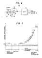
- the tachogenerator 2 generates 60 impulses per revolution for a sewing machine speed of 200 rpm for an input to output frequency ratio of 1:1.
- the detected pulse interval t will then be 5 milliseconds which corresponds to the T-value of 2 milliseconds.
- clutch coil lla is energized with a duty cycle of 40% and the sewing machine is run at a constant speed.
- the measured pulse interval t will increase by an amount determined by the transfer function.
- An acceleration signal is generated from arithmetic unit 8 to trigger flip-flop 9c, so that clutch coil lla is energized with a duty cycle greater than 40%. Since the sewing machine speed is proportional to an average value of successsive energization'times of coils lla and llb, an increase in the duty cycle results in acceleration of the sewing machine until it reaches 200 rpm. Conversely, a decrease in sewing machine load results in a decrease in duty cycle for clutch energization until the sewing machine speed decreases to 200 rpm.
- the frequency dividing factor is increased to an appropriate value. For example, a dividing factor of 2 will result in the measured pulse interval t being doubled with a corresponding increase in clutch duty cycle and the sewing machine speed increases to 400 rpm. With the system so stabilized, the pulse interval t and hence the duty cycle assumes the same value as when the sewing machine was previously run at 200 rpm for a unity frequency division ratio, so that the measured interval t and duty cycle values are maintained constant once the system is stabilized to a new division ratio.
- the operating speed of sewing machine 1 can thus be varied at increments of an integral multiple of 200 rpm from the minimum speed of 200 rpm.
- the speed setting circuit 5 comprises a digital speed setting device 50 which is manually operated in response to the operator's foot pedal 51 which is pivotally movable between a backwardly fully depresed position to a forwardly fully depressed position with a neutral position therebetween.
- the speed setting device 50 includes a permanent magnet, not shown, mounted for rotation with the foot pedal 51 and a magnetic sensor stationarily mounted with respect to the magnet to generate a voltage signal representing the orientation of the foot pedal.
- Fig. 2 A typical example of circuits for generating position indicating signals is shown in Fig. 2 in which a magnetoresistive element 18 is supplied with a current from a voltage source Vcc through a resistor 17.
- the voltage developed in the element 18 is coupled to the inverting and noninverting inputs of a differential amplifier formed by an operational amplifier 19, and resistors 20 to 23.
- the output of the differential amplifier is coupled to an analog-digital converter 24 where the input voltage is converted to a 5-bit binary code.
- the 5-bit binary signal is applied to a read only memory 52 and also to a binary-to-decimal converter 53.
- the 5-bit binary codes from “00000” to “11111” are organized so that binary codes “00000” to “00101” (corresponding to decimal numbers 0 to 5) are assigned to six backward pedal positions for signifying that the sewing machine is to be operated at a low speed for thread cutting operation.
- the binary codes "00110" to “01100” are assigned to seven pedal positions for signifying that the pedal is in a neutral position for stopping the sewing machine.
- The binary codes "01101" to "11111” are assigned to nineteen forward pedal positions for signifying that the sewing machine is to operated at variable high speeds.
- speed control data which is read output of the memory into the variable frequency divider 4 in response to the pedal position binary code from the analog-digital converter 24 to set the frequency dividing factor of the divider 4 according to the amount of pedal depression.
- data representing a unity frequency dividing factor is stored in cell locations of the memory 52 which are addressed by pedal position binary codes "00000" to "10010” (corresponding to decimal numbers 0 to 18), so that the sewing machine speed is set at a predetermined low speed, typically at 200 rpm.
- Data representing frequency dividing factors 2 to 14 are stored in cell locations addressed by binary codes "10011” to "11111” (corresponding to decimal numbers-19 to 31) to operate the machine at a variable speed which is an integral multiple of 200 rpm.
- the binary-to-decimal converter 53 provides conversion of binary codes "00000" to "11111” to decimal numbers 0 to 31.
- the decimal outputs 0 to 5 are coupled to a "thread cutter” OR gate 54 and the decimal outputs 6 to 12 are applied to a "neutral position” OR gate 55, the decimal outputs 13 to 31 being applied to a "variable speed” OR gate 56.
- the outputs of the OR gates 54 to 56 are connected to a logic circuit 57.
- the speed setting circuit 5 further includes a needle-down position detector 58 and a needle-up position detector 59 which are operatively coupled to the armshaft of the sewing machine to detect its needle-down and needle-up positions to generate corresponding needle position signals for application to the logic circuit 57.
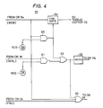
- FIG. 4 Details of the logic circuit 57 are illustrated in Fig. 4.
- the OR gate 56 When the foot pedal 51 is depressed forward from the neutral position, the OR gate 56 will generate an output which is supplied through an OR gate 60 and thence to the OR gate 9f to reset the flip-flops 9c and 9d.
- a corresponding speed control datum is read out of the memory 52 and fed to the variable frequency divider 4 so that the sewing machine is operated at a variable speed depending on the amount of forward depression of the foot pedal 51.
- the OR gate 55 When the foot pedal 51 is returned to the neutral position, the OR gate 55 will generate an output which is fed to an input of an AND gate 61 which takes its another input from the needle-down position sensor 58. Therefore, when the needle subsequently comes to the downward position, the AND gate 61 generates an output which is passed through an OR gate 62 to a monostable multivibrator 63 and also to the OR gate 60 to reset the flip-flops 9c and 9d.
- the output of the monostable multivibrator 63 is connected to the solenoid brake llb to briefly energize.it for stopping the sewing machine 1.
- the OR gate 54 If the foot pedal is depressed backward for thread cutting operation, the OR gate 54 generates an output which is applied through an inhibit gate 64 to a thread cutter 70 and also to an input of an AND gate 65 which takes its another input from the needle-up position detector 59. The sewing speed thus decreases to 200 rpm and the thread cutter 70 is operated to cut off the needle thread.
- the AND gater 65 When the needle comes to-the upward position, the AND gater 65 is activated. The output of AND gate 65 is used to close the gate 64 to de-energize the thread cutter 70 and reset the flip-flops 9c and 9d through OR gate 62 to energize the monostable multivibrator 63 for operating the solenoid brake llb to stop the machine.
- pulse shaping circuit 3 variable frequency divider 4
- counter means 6 latch 7
- arithmetic unit 8 pulse generator means 9 part of the manual speed setting device 50, read only memory 52, and logic circuit 57 are economically realized by microcomputer.
Landscapes
- Engineering & Computer Science (AREA)
- Mechanical Engineering (AREA)
- Textile Engineering (AREA)
- Power Engineering (AREA)
- Sewing Machines And Sewing (AREA)
- Control Of Electric Motors In General (AREA)
Applications Claiming Priority (2)
| Application Number | Priority Date | Filing Date | Title |
|---|---|---|---|
| JP91875/81 | 1981-06-15 | ||
| JP56091875A JPS57208881A (en) | 1981-06-15 | 1981-06-15 | Driving system for sewing machine |
Publications (2)
| Publication Number | Publication Date |
|---|---|
| EP0068713A2 true EP0068713A2 (de) | 1983-01-05 |
| EP0068713A3 EP0068713A3 (de) | 1983-05-04 |
Family
ID=14038726
Family Applications (1)
| Application Number | Title | Priority Date | Filing Date |
|---|---|---|---|
| EP82303107A Withdrawn EP0068713A3 (de) | 1981-06-15 | 1982-06-15 | Nähmaschine mit digitaler Regelschaltung |
Country Status (5)
| Country | Link |
|---|---|
| US (1) | US4517909A (de) |
| EP (1) | EP0068713A3 (de) |
| JP (1) | JPS57208881A (de) |
| KR (1) | KR850001708B1 (de) |
| CA (1) | CA1184274A (de) |
Cited By (4)
| Publication number | Priority date | Publication date | Assignee | Title |
|---|---|---|---|---|
| FR2539431A1 (fr) * | 1983-01-17 | 1984-07-20 | Prouvost Sa | Procede d'automatisation au moins partielle d'une operation de couture et machine partiellement automatisee pour sa mise en oeuvre |
| GB2162341A (en) * | 1984-07-27 | 1986-01-29 | Ae Plc | Automatic vehicle speed control system |
| GB2187311A (en) * | 1984-07-27 | 1987-09-03 | Ae Plc | Automatic vehicle speed control system |
| EP0646670A1 (de) * | 1993-10-01 | 1995-04-05 | Kessler GmbH | Vorrichtung zur Steuerung von Maschinen |
Families Citing this family (11)
| Publication number | Priority date | Publication date | Assignee | Title |
|---|---|---|---|---|
| JPS62106796A (ja) * | 1985-11-05 | 1987-05-18 | ブラザー工業株式会社 | ミシンの布押え昇降装置 |
| JPH0655236B2 (ja) * | 1985-11-06 | 1994-07-27 | 松下電器産業株式会社 | ミシン制御装置 |
| IT1186398B (it) * | 1985-11-26 | 1987-11-26 | Elemac Spa | Apparecchiatura di controllo di velocita',di posizione e di funzioni specifiche per macchine da cucire industriali,relizzata in tecnica digitale con "input" a variazione di induttanza |
| JP2641156B2 (ja) * | 1986-07-03 | 1997-08-13 | ブラザー工業 株式会社 | ミシンにおけるモータ制御装置 |
| JPH0354707Y2 (de) * | 1986-07-10 | 1991-12-03 | ||
| JPH0255590A (ja) * | 1988-08-16 | 1990-02-23 | Mitsubishi Electric Corp | モータ制御装置 |
| US5189968A (en) * | 1990-09-17 | 1993-03-02 | Brown Group, Inc. | Digital controller with A.C. induction drive for sewing machines |
| FR2689257B1 (fr) * | 1992-03-31 | 1996-12-13 | Valeo Electronique | Emetteur de commandes, recepteur adapte et systeme de commande pour dispositif d'essuyage de vehicules |
| US5587634A (en) * | 1994-11-29 | 1996-12-24 | Ara Electronics Corp. | Human body actuated control apparatus and system for commercial sewing machines |
| US7062349B2 (en) * | 1999-06-29 | 2006-06-13 | Frankl & Kirchner Gmbh & Co. K.G. | Control equipment for an industrial sewing machine |
| JP2010284364A (ja) * | 2009-06-12 | 2010-12-24 | Brother Ind Ltd | 縫製装置及びプログラム |
Family Cites Families (25)
| Publication number | Priority date | Publication date | Assignee | Title |
|---|---|---|---|---|
| BE650634A (de) * | ||||
| US2978693A (en) * | 1955-11-10 | 1961-04-04 | Bendix Corp | Analog to digital conversion system |
| US3268788A (en) * | 1963-01-09 | 1966-08-23 | Minnesota Mining & Mfg | Phase difference speed control system |
| GB1108154A (en) * | 1964-05-06 | 1968-04-03 | Ass Elect Ind | Improvements relating to frequency control circuits |
| FR1453454A (fr) * | 1965-08-10 | 1966-06-03 | Comp Generale Electricite | Procédé et dispositif pour le réglage de la vitesse d'un mobile |
| US3514685A (en) * | 1967-04-24 | 1970-05-26 | Fan Tron Corp | Optical speed transducer |
| US3543116A (en) * | 1968-05-01 | 1970-11-24 | Avtron Mfg Inc | Digital variable speed controller comparing a tachometer pulse source with a reference |
| US3621352A (en) * | 1969-03-19 | 1971-11-16 | Gen Electric | Inverter-control system for ac motor with pulse-locked closed loop frequency multiplier |
| US3731301A (en) * | 1971-07-06 | 1973-05-01 | Plessey Handel Investment Ag | Methods of detecting rotation speed |
| DE2412895B2 (de) * | 1974-03-18 | 1980-10-16 | Georgii-Kobold August Heine Kg, 7022 Leinfelden-Echterdingen | Drehzahlregelschaltung für eine Nähmaschinenantriebsvorrichtung mit einem Kupplungsmotor |
| JPS5185412A (en) * | 1975-01-20 | 1976-07-27 | Hitachi Ltd | Kaitenkino hensokuseigyohoshiki |
| JPS5943193B2 (ja) * | 1975-09-23 | 1984-10-20 | 株式会社日立製作所 | 工業用ミシンの制御装置 |
| FR2339202A1 (fr) * | 1976-01-26 | 1977-08-19 | Penet Pierre | Ensemble de commande d'un organe electrique ou hydraulique a fonctionnement periodique et dispositif de mesure du debit d'un fluide incorporant un tel ensemble |
| US4052646A (en) * | 1976-02-24 | 1977-10-04 | Molins Machine Company, Inc. | Speed control system for a corrugator |
| JPS52151809A (en) * | 1976-06-12 | 1977-12-16 | Hitachi Ltd | Danger prevention device of sewing machine driven by motor |
| US4139808A (en) * | 1976-10-08 | 1979-02-13 | Maruzen Sewing Machine Co., Ltd. | Control apparatus for electrically driven sewing machine |
| JPS5389539A (en) * | 1977-01-14 | 1978-08-07 | Hitachi Ltd | Motor driven sewing machine controller |
| US4153863A (en) * | 1977-04-20 | 1979-05-08 | Colt Industries Operating Corp. (Pratt & Whitney Machine Tool Division) | DC Motor controller |
| JPS5470150A (en) * | 1977-11-15 | 1979-06-05 | Tokyo Juki Industrial Co Ltd | Controller for sewing machine |
| JPS5479384A (en) * | 1977-12-06 | 1979-06-25 | Matsushita Electric Ind Co Ltd | System of synchronously leading in phase locked loop |
| US4227137A (en) * | 1978-05-30 | 1980-10-07 | Hartman Metal Fabricators, Inc. | Digital tach and slip signal motor control |
| JPS55150793A (en) * | 1979-05-10 | 1980-11-22 | Tokyo Juki Ind Co Ltd | Speed-control device for sewing machine |
| JPS55162892A (en) * | 1979-06-06 | 1980-12-18 | Hitachi Ltd | Speed controller for motor |
| US4386301A (en) * | 1979-10-26 | 1983-05-31 | Matsushita Electric Industrial Co., Ltd. | Digital speed control system for sewing machines |
| US4298832A (en) * | 1980-03-14 | 1981-11-03 | The Singer Company | Digital motor speed controller |
-
1981
- 1981-06-15 JP JP56091875A patent/JPS57208881A/ja active Granted
-
1982
- 1982-06-03 KR KR8202487A patent/KR850001708B1/ko not_active Expired
- 1982-06-11 US US06/387,433 patent/US4517909A/en not_active Expired - Lifetime
- 1982-06-14 CA CA000405070A patent/CA1184274A/en not_active Expired
- 1982-06-15 EP EP82303107A patent/EP0068713A3/de not_active Withdrawn
Cited By (7)
| Publication number | Priority date | Publication date | Assignee | Title |
|---|---|---|---|---|
| FR2539431A1 (fr) * | 1983-01-17 | 1984-07-20 | Prouvost Sa | Procede d'automatisation au moins partielle d'une operation de couture et machine partiellement automatisee pour sa mise en oeuvre |
| EP0117170A1 (de) * | 1983-01-17 | 1984-08-29 | Prouvost S.A. | Nähverfahren und automatisierte Nähmaschine dafür |
| US4593633A (en) * | 1983-01-17 | 1986-06-10 | Prouvost S.A. | Process for at least partly automating sewing operations and sewing machine therefor |
| GB2162341A (en) * | 1984-07-27 | 1986-01-29 | Ae Plc | Automatic vehicle speed control system |
| GB2187311A (en) * | 1984-07-27 | 1987-09-03 | Ae Plc | Automatic vehicle speed control system |
| US4737913A (en) * | 1984-07-27 | 1988-04-12 | Ae Plc | Automatic speed control systems |
| EP0646670A1 (de) * | 1993-10-01 | 1995-04-05 | Kessler GmbH | Vorrichtung zur Steuerung von Maschinen |
Also Published As
| Publication number | Publication date |
|---|---|
| CA1184274A (en) | 1985-03-19 |
| JPS6223594B2 (de) | 1987-05-23 |
| JPS57208881A (en) | 1982-12-22 |
| US4517909A (en) | 1985-05-21 |
| KR850001708B1 (ko) | 1985-11-26 |
| KR840000701A (ko) | 1984-02-27 |
| EP0068713A3 (de) | 1983-05-04 |
Similar Documents
| Publication | Publication Date | Title |
|---|---|---|
| EP0068713A2 (de) | Nähmaschine mit digitaler Regelschaltung | |
| US4386301A (en) | Digital speed control system for sewing machines | |
| US3411058A (en) | Acceleration deceleration control circuit for a stepping motor | |
| CA1096438A (en) | Stepping motor control circuit | |
| US5089759A (en) | Electrical motor position controller | |
| EP0067649B2 (de) | Nähmaschine mit Sanftanlaufschaltkreis | |
| EP0067072B1 (de) | Nähmaschine mit Gedächtnis zur Erzeugung eines Geschwindigkeitsregelsignales in Abhängigkeit von den Betriebszuständen | |
| EP0104913B1 (de) | Schaltung zum Regeln der Geschwindigkeit für eine Nähmaschine und der Stellung der Nähnadel | |
| EP0091084B1 (de) | Nähmaschinensteuergerät | |
| JPS62106799A (ja) | ミシン制御装置 | |
| US4377778A (en) | Sewing machine speed control system having quick response characteristic | |
| JPS58173591A (ja) | ミシン速度設定装置 | |
| JPS6223590B2 (de) | ||
| JPS6366555B2 (de) | ||
| JPS642397B2 (de) | ||
| JPS6366556B2 (de) | ||
| JPS58173587A (ja) | ミシン速度設定装置 | |
| JPS6366226B2 (de) | ||
| JPS627790B2 (de) | ||
| JPS6223591B2 (de) | ||
| JPS58173590A (ja) | ミシン制御装置 | |
| JPS6366552B2 (de) | ||
| JPS6042749B2 (ja) | ミシン制御装置 | |
| JPS6366554B2 (de) | ||
| JPS627791B2 (de) |
Legal Events
| Date | Code | Title | Description |
|---|---|---|---|
| PUAI | Public reference made under article 153(3) epc to a published international application that has entered the european phase |
Free format text: ORIGINAL CODE: 0009012 |
|
| AK | Designated contracting states |
Designated state(s): DE FR GB |
|
| PUAL | Search report despatched |
Free format text: ORIGINAL CODE: 0009013 |
|
| AK | Designated contracting states |
Designated state(s): DE FR GB |
|
| 17P | Request for examination filed |
Effective date: 19831001 |
|
| STAA | Information on the status of an ep patent application or granted ep patent |
Free format text: STATUS: THE APPLICATION IS DEEMED TO BE WITHDRAWN |
|
| 18D | Application deemed to be withdrawn |
Effective date: 19851107 |
|
| RIN1 | Information on inventor provided before grant (corrected) |
Inventor name: DOHI, TAKASHI Inventor name: SHINOZAKI, NOZOMU Inventor name: NEKI, SHIGEO |